EP2226448A2 - Panneau isolant de montage de saut de loup - Google Patents
Panneau isolant de montage de saut de loup Download PDFInfo
- Publication number
- EP2226448A2 EP2226448A2 EP10002118A EP10002118A EP2226448A2 EP 2226448 A2 EP2226448 A2 EP 2226448A2 EP 10002118 A EP10002118 A EP 10002118A EP 10002118 A EP10002118 A EP 10002118A EP 2226448 A2 EP2226448 A2 EP 2226448A2
- Authority
- EP
- European Patent Office
- Prior art keywords
- insulation
- light shaft
- building wall
- thermal insulation
- dowel
- Prior art date
- Legal status (The legal status is an assumption and is not a legal conclusion. Google has not performed a legal analysis and makes no representation as to the accuracy of the status listed.)
- Granted
Links
Images



Classifications
-
- E—FIXED CONSTRUCTIONS
- E04—BUILDING
- E04F—FINISHING WORK ON BUILDINGS, e.g. STAIRS, FLOORS
- E04F17/00—Vertical ducts; Channels, e.g. for drainage
- E04F17/06—Light shafts, e.g. for cellars
-
- E—FIXED CONSTRUCTIONS
- E04—BUILDING
- E04B—GENERAL BUILDING CONSTRUCTIONS; WALLS, e.g. PARTITIONS; ROOFS; FLOORS; CEILINGS; INSULATION OR OTHER PROTECTION OF BUILDINGS
- E04B1/00—Constructions in general; Structures which are not restricted either to walls, e.g. partitions, or floors or ceilings or roofs
- E04B1/62—Insulation or other protection; Elements or use of specified material therefor
- E04B1/74—Heat, sound or noise insulation, absorption, or reflection; Other building methods affording favourable thermal or acoustical conditions, e.g. accumulating of heat within walls
- E04B1/76—Heat, sound or noise insulation, absorption, or reflection; Other building methods affording favourable thermal or acoustical conditions, e.g. accumulating of heat within walls specifically with respect to heat only
- E04B1/762—Exterior insulation of exterior walls
- E04B1/7637—Anchoring of separate elements through the lining to the wall
Definitions
- the present invention relates to a thermal insulation for a building wall in the basement area of a house with an insulation which is arranged on the building wall. Furthermore, the present invention relates to a method for mounting a light well on a thermally insulated with a Perimeterdämmung building wall.
- Thermal insulation is becoming more and more important nowadays. It is particularly desirable to insulate the basement area of a house.
- the arrangement of a light shaft which was arranged in the region of openings in the building wall in the basement area, has proven to be very expensive. Partly holes were pre-drilled in the building wall, to which then the light shaft should be attached. However, after arranging the thermal insulation, it was extremely difficult to find these pre-drilled holes.
- Another solution according to the utility model DE 203 03 405 U1 Proposes to provide the insulation in the area of the light shaft in great numbers and to piece it around the light shaft. This form of insulation is extremely expensive. Furthermore, the fortifications represent thermal bridges and the subsequent plastering is very expensive.
- the problem is solved with a thermal insulation for a building wall in the basement area of a house, with an insulation, which is arranged on the building wall, wherein the insulation has attachment points to which a light shaft can be attached.
- the present invention relates to the thermal insulation for a building wall in the basement area of a house with an insulation on the building wall is arranged.
- the insulation is glued to the building wall, but can also be positively and / or non-positively fastened, for example with screws on the basement wall.
- the insulation has attachment points to which a light shaft can be attached.
- the light shaft is therefore attached only to the insulation and not on the building wall itself. It can therefore initially arranged the insulation on the building wall, in particular glued and then the light shaft are mounted on the insulation without having to be drilled in the building wall. As a result, the installation of the light shaft on an insulated basement wall is considerably simplified.
- the insulation carries the light shaft completely.
- the light shaft is not directly connected to the building wall.
- the light shaft is made of a plastic material.
- the light shaft is two-piece, with an upper and a lower part executed.
- the insulation consists of an insulating material whose thickness is particularly preferably at least 80 mm, preferably 100 mm or more.
- the insulating material is a so-called perimeter insulation.
- Perimeter insulation is the thermal insulation of earth-contacting components of buildings and structures on their outside. This can be both the insulation below the floor slab of a building as well as the wall insulation of an embedded in the ground basement exterior wall.
- the insulation must be resistant to water and pressure, therefore preferably closed-cell foam materials, eg. As extruded polystyrene foam boards or foam glass plates used.
- the insulation material is applied outside the waterproof layer (bituminous paint or plastic foil).
- the insulating material is preferably provided in the form of plates. These insulation boards are preferably glued to them Do not move if the backfill of the pit is set or if the light shaft is attached to the insulation.
- recycled materials such as glass foam granules and glass foam panels and / or mineral materials can be used as Perimeterdämmung.
- Glass foam granules are made, for example, from pure waste glass. Also conceivable is a combination of mineral and plastic materials as a mixture and / or as a multi-layer insulation.
- the insulation preferably has a lamination, in particular on the side of the insulating material facing away from the building wall.
- This lamination protects the insulating material in particular against mechanical influences and weathering, UV radiation, thus represents a substitute for a plaster and is used in the present case very particularly preferably as a facility for the light shaft and / or as a guide and / or support for a fastener , which is arranged in the insulation, in particular in the thermal insulation material.
- the lamination may be, for example, a sheet of mineral material, in particular fiber cement board or a plastic sheet. The lamination is positively / positively and / or positively connected to the insulation material.
- the attachment points are marked in / on the insulation and / or at least partially prefabricated, for example, predrilled.
- the fastening points are marked on the lining and / or at least partially incorporated therein.
- at least two fastening points are present at a height with which the light shaft can be attached to the insulation on the right and left of an opening in the building wall.
- Very particular preference is given to several attachment points with each other, in particular in a certain grid, very particularly preferably, both right and left of a building wall opening marked and / or at least partially prefabricated.
- a fastening means is at least partially arranged.
- This attachment means preferably does not extend through the entire thickness of the insulation.
- the fastener is not on the Building wall and / or extends into this.
- the fastening means is a dowel, very particularly preferably a self-tapping dowel, which cuts a corresponding opening, in particular in the insulating material.
- the dowel connects positively and / or positively with the insulating material and / or with the lamination.
- the dowel on a collar which rests after its arrangement in the insulation on the insulating material or on the lamination.
- the dowel is screwed into the insulating material.
- the thermal insulation comprises an insert which is inserted between the wall and the window frame and / or the insulation and the window frame.
- the edges of the insulation facing the opening can be protected and / or the thermal insulation according to the invention can be protected against ingress of water behind the insulation, in particular during floods.
- both the interface window frame / insert and the interface insert / insulation is sealed with a sealant.
- Another object of the present invention is therefore a method for mounting a light shaft on a heat-insulated with an insulating building wall, in which the fastening means disposed in the insulation and the light shaft is attached thereto.
- a dowel is placed in the insulation.
- a self-tapping dowel is used, which cuts in particular in the insulating material and thus enters into a positive and / or non-positive connection with the thermal insulation material.
- the dowel is screwed so far into the thermal insulation material until a collar, the on Is located at the end of the anchor, preferably applied to the insulating material or on an existing lamination.
- the dowel does not necessarily have to have a collar
- the light shaft is then fastened by screws to the dowels.
- FIG. 1 shows the thermal insulation according to the invention on which a light shaft is arranged in three views.
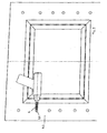
- FIG. 2 shows the thermal insulation according to the invention.
- FIG. 3 shows the arrangement of a dowel in the thermal insulation.
- FIG. 4 shows the light shaft attached to the insulation.
- FIG. 1 shows a building wall 1, in the present case, a basement wall, in which a cellar window is provided.
- This basement window has a window frame 2 and a window pane 3.
- the building wall 1 On its outer side, the building wall 1 is provided with an insulation 4, a so-called perimeter insulation 4, the area of the recess 1.1 being recessed.
- This insulation 4 is in the present case of an insulating material 4.3, which is glued to the building wall and from a lining 4.2 made of fiber cement, which is located on the side facing away from the building wall 1 and applied to the insulating material 4.3, preferably glued.
- the insulation is provided plate-shaped.
- the insulation 4 here in particular the lining 4.2, a plurality of attachment points 4.1, which are arranged one above the other in a, preferably vetikalen row each right and left of the window opening.
- the fastening points 4.1 in the present case bores that extend only through the lining, are each arranged at the same height to the right and left of the window.
- the holes to the right and left of the window are at least partially arranged in a certain, the same pitch. This makes it possible to arrange different types of light wells and / or different sizes of light wells in the region of the window opening, without the need for a large installation effort. If necessary, the connection points which are not required can be subsequently closed with a sealing material.
- a fastening means is preferably a dowel, which is very particularly preferably self-tapping screwed to the attachment points, in particular in the insulating material 4.3.
- This dowel is preferably completely or at least preferably so far screwed into the insulating material until an optionally arranged on him collar on the lining 4.2 or if no lamination is present, rests against the insulating material 4.3.
- the dowel extends only into the insulation material and does not touch the wall 1.
- the wall 1, which is located behind the insulation 4, must therefore not be drilled.
- the light shaft 5 consists in the present case of a lower part 5.1 and a height-displaceable arranged thereon upper part 5.2.
- both the lower part, and the upper part fastening hooks 5.3 which act with the screws 7, which are arranged in the dowels 6, positively and / or non-positively cooperate.
- the light shaft can also be made in one piece.
- the thermal insulation in the area within the light shaft on a cover 8 the Extent extends around the entire opening 1.1 and whose cross-section is L-shaped. This use has the particular task of protecting the thermal insulation on the side not provided with a lamination from mechanical influences, UV radiation and weathering, but also in order to provide an overall watertight, ie also flood-protected wall opening 1.1.
- FIG. 2 shows the insulation 4, which consists of a lying in the foreground lamination 4.2 and a parent behind Dämmmaterial 4.3.
- Both plates 4.2, 4.3 have a basement window opening.
- the basement window opening corresponds to the opening 1.1, which is arranged in the building wall.
- the insulation 4 is arranged on the building wall, in particular glued, that the opening in the insulation and the opening in the building wall are aligned. The insulation therefore does not have to be pieced in the area of a window, but can be arranged integrally on the building wall.
- Right and left of the opening, the insulation 4 each have a plurality of attachment points 4.1, which are arranged on the right and left in each case at the same height.
- the attachment points 4.1 are arranged one above the other in a certain preferred pitch.
- the attachment points 4.1 are holes in the present case, which extend only through the lining 4.2 and possibly slightly into the underlying insulation material 4.3 inside. In these attachment points 4.1. is, as shown at the bottom left, a dowel 6 screwed into it. This dowel acts self-tapping with the insulating material 4.3 together.
- FIG. 3 shows the arrangement of the anchor 6 in the attachment points 4.1.
- a rotating means here a hand tool, for example a drill
- the dowel is screwed into the attachment point and thereby cuts itself into the insulating material 4.3 inside.
- the mounted on the insulation 4 light shaft 5 is in FIG. 4 shown.
- the light shaft consists of a lower part 5.1 and a top part 5.2, wherein the upper part 5.2 is arranged vertically displaceable on the lower part 5.1.
- Both parts 5.1 are attached at the desired height to the already provided there attachment points 4.1 each right and left, with the first Lower part 5.1 attached to the insulation and then aligned the upper part to the desired height and connected there with the insulation.
- the mounting of the light shaft to the insulation is done with screws 7, which are arranged in the respective attachment points dowels 6 are rotated. Neither the dowels 6 nor the screws 7 extend into the building wall 1 into it.
- no drill sondem only a screwing tool is required for the assembly of the light shaft 5 on the insulation preferably no drill sondem only a screwing tool is required. At most, the lamination must be drilled in the event that the attachment points are only marked.
- the installation of the light shaft is therefore very simple.
- two dowels 6 are arranged at the desired marked or pre-drilled locations, here preferably self-tapping, screwed into the insulation 4.
- the building wall does not have to be drilled.
- the light shaft is fastened by screws 7 to the dowels.
- the light shaft can be provided in one piece, in two parts or even in three parts. For each execution of the light shaft this is usually covered with a grid.
Landscapes
- Engineering & Computer Science (AREA)
- Architecture (AREA)
- Civil Engineering (AREA)
- Structural Engineering (AREA)
- Physics & Mathematics (AREA)
- Acoustics & Sound (AREA)
- Electromagnetism (AREA)
- Building Environments (AREA)
Applications Claiming Priority (1)
| Application Number | Priority Date | Filing Date | Title |
|---|---|---|---|
| DE102009010910A DE102009010910A1 (de) | 2009-03-02 | 2009-03-02 | Lichtschacht-Montagedämmplatte |
Publications (3)
| Publication Number | Publication Date |
|---|---|
| EP2226448A2 true EP2226448A2 (fr) | 2010-09-08 |
| EP2226448A3 EP2226448A3 (fr) | 2012-06-06 |
| EP2226448B1 EP2226448B1 (fr) | 2015-02-11 |
Family
ID=42265497
Family Applications (1)
| Application Number | Title | Priority Date | Filing Date |
|---|---|---|---|
| EP10002118.7A Active EP2226448B1 (fr) | 2009-03-02 | 2010-03-02 | Panneau isolant de montage de saut de loup |
Country Status (2)
| Country | Link |
|---|---|
| EP (1) | EP2226448B1 (fr) |
| DE (2) | DE202009018102U1 (fr) |
Cited By (1)
| Publication number | Priority date | Publication date | Assignee | Title |
|---|---|---|---|---|
| EP2700768A3 (fr) * | 2012-07-06 | 2016-05-25 | MEA Bausysteme GmbH | Montage de saut de loup sans pont thermique |
Families Citing this family (2)
| Publication number | Priority date | Publication date | Assignee | Title |
|---|---|---|---|---|
| DE202014104561U1 (de) | 2014-09-24 | 2014-10-20 | Wolfa Bauelemente Aus Stahl Und Kunststoff Friedrich Wolfarth Gmbh & Co. Kg | Montagevorrichtung zur Befestigung eines Lichtschachts |
| EP3839171B1 (fr) | 2019-12-20 | 2022-10-05 | MEA Bautechnik GmbH | Plaque isolante de montage pour puits de lumière |
Family Cites Families (9)
| Publication number | Priority date | Publication date | Assignee | Title |
|---|---|---|---|---|
| DE29507419U1 (de) * | 1995-05-04 | 1995-08-10 | Hieber, Alexander, 86441 Zusmarshausen | Bau-Fertigteil zum Einbau in außenisolierte Wände, insbesondere Kellerwände |
| DE29805465U1 (de) * | 1998-03-25 | 1998-12-03 | Bruckbauer, Siegfried, 93138 Lappersdorf | Bauteil zur Befestigung eines Stockrahmens eines Gebäudefensters oder einer Gebäudetür in einer Gebäudeöffnung sowie Gebäudefenster oder Gebäudetür |
| DE29813808U1 (de) * | 1998-08-01 | 1998-10-22 | Beutelrock, Gerhard, 86343 Königsbrunn | Lichtschacht |
| DE29901728U1 (de) * | 1999-01-26 | 1999-07-08 | Schüngel GmbH & Co. Iso Tec KG, 09235 Burkhardtsdorf | Anschluß für Fenster |
| DE19947913C2 (de) * | 1999-10-06 | 2002-08-29 | Karl-Heinz Fingerling | Befestigungselement zur Anbringung von Lasten an eine eine Wärmedämmung aufweisende Gebäudewand |
| DE10064679A1 (de) * | 2000-12-22 | 2002-07-04 | Fischer Artur Werke Gmbh | Abstandshalter für die Befestigung eines Bauteils an einer eine Dämmschicht aufweisenden Wand oder dgl., sowie Verfahren und Werkzeug zum Setzen des Abstandshalters |
| DE10241231B4 (de) * | 2002-03-11 | 2006-02-09 | Deutsche Rockwool Mineralwoll Gmbh + Co Ohg | Wärme- und/oder Schalldämmsystem sowie Dämmelement |
| DE20218721U1 (de) * | 2002-12-02 | 2003-02-13 | SyPro Schöck GmbH, 76534 Baden-Baden | Lichtschacht-Aufhängung |
| DE20303405U1 (de) | 2003-03-03 | 2003-07-17 | Josef Hain GmbH & Co. KG, 83561 Ramerberg | Wärmedämmelement |
-
2009
- 2009-03-02 DE DE202009018102U patent/DE202009018102U1/de not_active Expired - Lifetime
- 2009-03-02 DE DE102009010910A patent/DE102009010910A1/de not_active Withdrawn
-
2010
- 2010-03-02 EP EP10002118.7A patent/EP2226448B1/fr active Active
Cited By (2)
| Publication number | Priority date | Publication date | Assignee | Title |
|---|---|---|---|---|
| EP2700768A3 (fr) * | 2012-07-06 | 2016-05-25 | MEA Bausysteme GmbH | Montage de saut de loup sans pont thermique |
| EP3176346A1 (fr) * | 2012-07-06 | 2017-06-07 | MEA Bausysteme GmbH | Montage de puits de lumière sans pont thermique |
Also Published As
| Publication number | Publication date |
|---|---|
| EP2226448A3 (fr) | 2012-06-06 |
| DE102009010910A1 (de) | 2010-09-16 |
| EP2226448B1 (fr) | 2015-02-11 |
| DE202009018102U1 (de) | 2011-02-17 |
Similar Documents
| Publication | Publication Date | Title |
|---|---|---|
| EP3504386B1 (fr) | Maison modulaire | |
| EP2226448B1 (fr) | Panneau isolant de montage de saut de loup | |
| EP2700768B1 (fr) | Montage de puits de lumière sans pont thermique | |
| EP1842975B1 (fr) | Système de revêtement de sol pour jardin d'hiver et pièce d'ancrage associée | |
| EP3854975A1 (fr) | Huisserie enveloppante préfabriquée pour une ouverture de bâtiment, système composite d'isolation thermique, façade de bâtiment et bâtiment, comportant l'huisserie enveloppante et utilisation de l'huisserie enveloppante | |
| DE202014101779U1 (de) | Mauerelement mit rückseitiger Plattenbefestigung | |
| DE202008008925U1 (de) | Verkleidungselement für ein Außenmauerwerk im Bereich einer Fenster- oder Türlaibung | |
| EP3926117B1 (fr) | Système composite d'isolation thermique, façade pourvue de système composite d'isolation thermique, ainsi que son procédé de construction | |
| EP3091167B1 (fr) | Élément de fixation pour un cadre de fenêtre sur un plafond de bâtiment d'une construction, construction associée et procédé de fixation d'un cadre de fenêtre sur un plafond de bâtiment | |
| DE102015015604B4 (de) | Aufnahmeelement für eine Beschattungseinrichtung und Verfahren zum Befestigen eines solchen an der Außenseite eines Gebäudes | |
| AT525859A2 (de) | Dämmmodul für ein Gebäude | |
| EP3839171B1 (fr) | Plaque isolante de montage pour puits de lumière | |
| DE202012007697U1 (de) | Anputzleiste, Abschlussschiene und Putz-Eckleiste | |
| DE9303937U1 (de) | Sanitaerkabine | |
| DE20302588U1 (de) | Bauwerk mit angebautem Aufzug, Fertigwandteil und Aufzugschacht | |
| DE102005040388A1 (de) | Stützverbund für Gebäude sowie Teile zu seiner Herstellung | |
| DE10318119A1 (de) | Systemwand | |
| DE202014004059U1 (de) | Fertigkeller | |
| DE102015011605A1 (de) | Glasfassade mit Hohlprofil als Pfosten | |
| DE102019220489A1 (de) | Lichtschacht-Montagedämmplatte | |
| DE202015102067U1 (de) | Außenwandelement in Holzrahmenkonstruktion | |
| DE10219504B4 (de) | Dämmstoffplatte | |
| DE102011017089A1 (de) | Gebäudewand aus Beton mit einer verlorenen Schalung als Laibung für eine Ausnehmung in der Gebäudewand | |
| EP2634514B1 (fr) | Dispositif et procédé destinés à réaliser une étanchéification entre le mur et le sol au niveau de l'isolation dans des pièces | |
| AT502482B1 (de) | Verfahren zur herstellung von wänden von gebäuden |
Legal Events
| Date | Code | Title | Description |
|---|---|---|---|
| PUAI | Public reference made under article 153(3) epc to a published international application that has entered the european phase |
Free format text: ORIGINAL CODE: 0009012 |
|
| AK | Designated contracting states |
Kind code of ref document: A2 Designated state(s): AT BE BG CH CY CZ DE DK EE ES FI FR GB GR HR HU IE IS IT LI LT LU LV MC MK MT NL NO PL PT RO SE SI SK SM TR |
|
| AX | Request for extension of the european patent |
Extension state: AL BA ME RS |
|
| 17P | Request for examination filed |
Effective date: 20101111 |
|
| PUAL | Search report despatched |
Free format text: ORIGINAL CODE: 0009013 |
|
| AK | Designated contracting states |
Kind code of ref document: A3 Designated state(s): AT BE BG CH CY CZ DE DK EE ES FI FR GB GR HR HU IE IS IT LI LT LU LV MC MK MT NL NO PL PT RO SE SI SK SM TR |
|
| AX | Request for extension of the european patent |
Extension state: AL BA ME RS |
|
| RIC1 | Information provided on ipc code assigned before grant |
Ipc: E04B 1/78 20060101ALI20120427BHEP Ipc: E04B 1/76 20060101ALI20120427BHEP Ipc: E04F 17/06 20060101AFI20120427BHEP |
|
| 17Q | First examination report despatched |
Effective date: 20140123 |
|
| GRAP | Despatch of communication of intention to grant a patent |
Free format text: ORIGINAL CODE: EPIDOSNIGR1 |
|
| GRAS | Grant fee paid |
Free format text: ORIGINAL CODE: EPIDOSNIGR3 |
|
| INTG | Intention to grant announced |
Effective date: 20141216 |
|
| GRAA | (expected) grant |
Free format text: ORIGINAL CODE: 0009210 |
|
| AK | Designated contracting states |
Kind code of ref document: B1 Designated state(s): AT BE BG CH CY CZ DE DK EE ES FI FR GB GR HR HU IE IS IT LI LT LU LV MC MK MT NL NO PL PT RO SE SI SK SM TR |
|
| REG | Reference to a national code |
Ref country code: GB Ref legal event code: FG4D Free format text: NOT ENGLISH |
|
| REG | Reference to a national code |
Ref country code: CH Ref legal event code: EP |
|
| REG | Reference to a national code |
Ref country code: IE Ref legal event code: FG4D Free format text: LANGUAGE OF EP DOCUMENT: GERMAN |
|
| REG | Reference to a national code |
Ref country code: AT Ref legal event code: REF Ref document number: 709992 Country of ref document: AT Kind code of ref document: T Effective date: 20150315 |
|
| REG | Reference to a national code |
Ref country code: DE Ref legal event code: R096 Ref document number: 502010008851 Country of ref document: DE Effective date: 20150326 |
|
| REG | Reference to a national code |
Ref country code: CH Ref legal event code: NV Representative=s name: MICHELI AND CIE SA, CH |
|
| REG | Reference to a national code |
Ref country code: NL Ref legal event code: VDEP Effective date: 20150211 |
|
| REG | Reference to a national code |
Ref country code: LT Ref legal event code: MG4D |
|
| PG25 | Lapsed in a contracting state [announced via postgrant information from national office to epo] |
Ref country code: SE Free format text: LAPSE BECAUSE OF FAILURE TO SUBMIT A TRANSLATION OF THE DESCRIPTION OR TO PAY THE FEE WITHIN THE PRESCRIBED TIME-LIMIT Effective date: 20150211 Ref country code: HR Free format text: LAPSE BECAUSE OF FAILURE TO SUBMIT A TRANSLATION OF THE DESCRIPTION OR TO PAY THE FEE WITHIN THE PRESCRIBED TIME-LIMIT Effective date: 20150211 Ref country code: NO Free format text: LAPSE BECAUSE OF FAILURE TO SUBMIT A TRANSLATION OF THE DESCRIPTION OR TO PAY THE FEE WITHIN THE PRESCRIBED TIME-LIMIT Effective date: 20150511 Ref country code: LT Free format text: LAPSE BECAUSE OF FAILURE TO SUBMIT A TRANSLATION OF THE DESCRIPTION OR TO PAY THE FEE WITHIN THE PRESCRIBED TIME-LIMIT Effective date: 20150211 Ref country code: FI Free format text: LAPSE BECAUSE OF FAILURE TO SUBMIT A TRANSLATION OF THE DESCRIPTION OR TO PAY THE FEE WITHIN THE PRESCRIBED TIME-LIMIT Effective date: 20150211 Ref country code: ES Free format text: LAPSE BECAUSE OF FAILURE TO SUBMIT A TRANSLATION OF THE DESCRIPTION OR TO PAY THE FEE WITHIN THE PRESCRIBED TIME-LIMIT Effective date: 20150211 |
|
| PG25 | Lapsed in a contracting state [announced via postgrant information from national office to epo] |
Ref country code: LV Free format text: LAPSE BECAUSE OF FAILURE TO SUBMIT A TRANSLATION OF THE DESCRIPTION OR TO PAY THE FEE WITHIN THE PRESCRIBED TIME-LIMIT Effective date: 20150211 Ref country code: GR Free format text: LAPSE BECAUSE OF FAILURE TO SUBMIT A TRANSLATION OF THE DESCRIPTION OR TO PAY THE FEE WITHIN THE PRESCRIBED TIME-LIMIT Effective date: 20150512 Ref country code: NL Free format text: LAPSE BECAUSE OF FAILURE TO SUBMIT A TRANSLATION OF THE DESCRIPTION OR TO PAY THE FEE WITHIN THE PRESCRIBED TIME-LIMIT Effective date: 20150211 Ref country code: IS Free format text: LAPSE BECAUSE OF FAILURE TO SUBMIT A TRANSLATION OF THE DESCRIPTION OR TO PAY THE FEE WITHIN THE PRESCRIBED TIME-LIMIT Effective date: 20150611 |
|
| PG25 | Lapsed in a contracting state [announced via postgrant information from national office to epo] |
Ref country code: EE Free format text: LAPSE BECAUSE OF FAILURE TO SUBMIT A TRANSLATION OF THE DESCRIPTION OR TO PAY THE FEE WITHIN THE PRESCRIBED TIME-LIMIT Effective date: 20150211 Ref country code: DK Free format text: LAPSE BECAUSE OF FAILURE TO SUBMIT A TRANSLATION OF THE DESCRIPTION OR TO PAY THE FEE WITHIN THE PRESCRIBED TIME-LIMIT Effective date: 20150211 Ref country code: CZ Free format text: LAPSE BECAUSE OF FAILURE TO SUBMIT A TRANSLATION OF THE DESCRIPTION OR TO PAY THE FEE WITHIN THE PRESCRIBED TIME-LIMIT Effective date: 20150211 Ref country code: RO Free format text: LAPSE BECAUSE OF FAILURE TO SUBMIT A TRANSLATION OF THE DESCRIPTION OR TO PAY THE FEE WITHIN THE PRESCRIBED TIME-LIMIT Effective date: 20150211 Ref country code: SK Free format text: LAPSE BECAUSE OF FAILURE TO SUBMIT A TRANSLATION OF THE DESCRIPTION OR TO PAY THE FEE WITHIN THE PRESCRIBED TIME-LIMIT Effective date: 20150211 |
|
| REG | Reference to a national code |
Ref country code: DE Ref legal event code: R097 Ref document number: 502010008851 Country of ref document: DE |
|
| PG25 | Lapsed in a contracting state [announced via postgrant information from national office to epo] |
Ref country code: MC Free format text: LAPSE BECAUSE OF FAILURE TO SUBMIT A TRANSLATION OF THE DESCRIPTION OR TO PAY THE FEE WITHIN THE PRESCRIBED TIME-LIMIT Effective date: 20150211 Ref country code: PL Free format text: LAPSE BECAUSE OF FAILURE TO SUBMIT A TRANSLATION OF THE DESCRIPTION OR TO PAY THE FEE WITHIN THE PRESCRIBED TIME-LIMIT Effective date: 20150211 |
|
| PLBE | No opposition filed within time limit |
Free format text: ORIGINAL CODE: 0009261 |
|
| STAA | Information on the status of an ep patent application or granted ep patent |
Free format text: STATUS: NO OPPOSITION FILED WITHIN TIME LIMIT |
|
| REG | Reference to a national code |
Ref country code: FR Ref legal event code: ST Effective date: 20151130 |
|
| REG | Reference to a national code |
Ref country code: IE Ref legal event code: MM4A |
|
| 26N | No opposition filed |
Effective date: 20151112 |
|
| GBPC | Gb: european patent ceased through non-payment of renewal fee |
Effective date: 20150511 |
|
| PG25 | Lapsed in a contracting state [announced via postgrant information from national office to epo] |
Ref country code: IE Free format text: LAPSE BECAUSE OF NON-PAYMENT OF DUE FEES Effective date: 20150302 |
|
| PG25 | Lapsed in a contracting state [announced via postgrant information from national office to epo] |
Ref country code: FR Free format text: LAPSE BECAUSE OF NON-PAYMENT OF DUE FEES Effective date: 20150413 Ref country code: SI Free format text: LAPSE BECAUSE OF FAILURE TO SUBMIT A TRANSLATION OF THE DESCRIPTION OR TO PAY THE FEE WITHIN THE PRESCRIBED TIME-LIMIT Effective date: 20150211 |
|
| PG25 | Lapsed in a contracting state [announced via postgrant information from national office to epo] |
Ref country code: GB Free format text: LAPSE BECAUSE OF NON-PAYMENT OF DUE FEES Effective date: 20150511 |
|
| PG25 | Lapsed in a contracting state [announced via postgrant information from national office to epo] |
Ref country code: MT Free format text: LAPSE BECAUSE OF FAILURE TO SUBMIT A TRANSLATION OF THE DESCRIPTION OR TO PAY THE FEE WITHIN THE PRESCRIBED TIME-LIMIT Effective date: 20150211 |
|
| PG25 | Lapsed in a contracting state [announced via postgrant information from national office to epo] |
Ref country code: BG Free format text: LAPSE BECAUSE OF FAILURE TO SUBMIT A TRANSLATION OF THE DESCRIPTION OR TO PAY THE FEE WITHIN THE PRESCRIBED TIME-LIMIT Effective date: 20150211 Ref country code: HU Free format text: LAPSE BECAUSE OF FAILURE TO SUBMIT A TRANSLATION OF THE DESCRIPTION OR TO PAY THE FEE WITHIN THE PRESCRIBED TIME-LIMIT; INVALID AB INITIO Effective date: 20100302 Ref country code: SM Free format text: LAPSE BECAUSE OF FAILURE TO SUBMIT A TRANSLATION OF THE DESCRIPTION OR TO PAY THE FEE WITHIN THE PRESCRIBED TIME-LIMIT Effective date: 20150211 |
|
| PG25 | Lapsed in a contracting state [announced via postgrant information from national office to epo] |
Ref country code: CY Free format text: LAPSE BECAUSE OF FAILURE TO SUBMIT A TRANSLATION OF THE DESCRIPTION OR TO PAY THE FEE WITHIN THE PRESCRIBED TIME-LIMIT Effective date: 20150211 |
|
| PG25 | Lapsed in a contracting state [announced via postgrant information from national office to epo] |
Ref country code: BE Free format text: LAPSE BECAUSE OF NON-PAYMENT OF DUE FEES Effective date: 20150331 Ref country code: PT Free format text: LAPSE BECAUSE OF FAILURE TO SUBMIT A TRANSLATION OF THE DESCRIPTION OR TO PAY THE FEE WITHIN THE PRESCRIBED TIME-LIMIT Effective date: 20150611 |
|
| PG25 | Lapsed in a contracting state [announced via postgrant information from national office to epo] |
Ref country code: TR Free format text: LAPSE BECAUSE OF FAILURE TO SUBMIT A TRANSLATION OF THE DESCRIPTION OR TO PAY THE FEE WITHIN THE PRESCRIBED TIME-LIMIT Effective date: 20150211 |
|
| PG25 | Lapsed in a contracting state [announced via postgrant information from national office to epo] |
Ref country code: LU Free format text: LAPSE BECAUSE OF NON-PAYMENT OF DUE FEES Effective date: 20150302 |
|
| PG25 | Lapsed in a contracting state [announced via postgrant information from national office to epo] |
Ref country code: MK Free format text: LAPSE BECAUSE OF FAILURE TO SUBMIT A TRANSLATION OF THE DESCRIPTION OR TO PAY THE FEE WITHIN THE PRESCRIBED TIME-LIMIT Effective date: 20150211 |
|
| PGFP | Annual fee paid to national office [announced via postgrant information from national office to epo] |
Ref country code: IT Payment date: 20250331 Year of fee payment: 16 |
|
| PGFP | Annual fee paid to national office [announced via postgrant information from national office to epo] |
Ref country code: CH Payment date: 20250401 Year of fee payment: 16 |
|
| REG | Reference to a national code |
Ref country code: CH Ref legal event code: U11 Free format text: ST27 STATUS EVENT CODE: U-0-0-U10-U11 (AS PROVIDED BY THE NATIONAL OFFICE) Effective date: 20260401 |
|
| PGFP | Annual fee paid to national office [announced via postgrant information from national office to epo] |
Ref country code: DE Payment date: 20260320 Year of fee payment: 17 |
|
| PGFP | Annual fee paid to national office [announced via postgrant information from national office to epo] |
Ref country code: AT Payment date: 20260319 Year of fee payment: 17 |