EP2226574A2 - Centrale de chauffage en bloc modulaire - Google Patents
Centrale de chauffage en bloc modulaire Download PDFInfo
- Publication number
- EP2226574A2 EP2226574A2 EP10002358A EP10002358A EP2226574A2 EP 2226574 A2 EP2226574 A2 EP 2226574A2 EP 10002358 A EP10002358 A EP 10002358A EP 10002358 A EP10002358 A EP 10002358A EP 2226574 A2 EP2226574 A2 EP 2226574A2
- Authority
- EP
- European Patent Office
- Prior art keywords
- module
- chp
- modules
- modular
- internal combustion
- Prior art date
- Legal status (The legal status is an assumption and is not a legal conclusion. Google has not performed a legal analysis and makes no representation as to the accuracy of the status listed.)
- Granted
Links
Images




Classifications
-
- F—MECHANICAL ENGINEERING; LIGHTING; HEATING; WEAPONS; BLASTING
- F24—HEATING; RANGES; VENTILATING
- F24H—FLUID HEATERS, e.g. WATER OR AIR HEATERS, HAVING HEAT-GENERATING MEANS, e.g. HEAT PUMPS, IN GENERAL
- F24H9/00—Details
- F24H9/14—Arrangements for connecting different sections, e.g. in water heaters
-
- F—MECHANICAL ENGINEERING; LIGHTING; HEATING; WEAPONS; BLASTING
- F01—MACHINES OR ENGINES IN GENERAL; ENGINE PLANTS IN GENERAL; STEAM ENGINES
- F01K—STEAM ENGINE PLANTS; STEAM ACCUMULATORS; ENGINE PLANTS NOT OTHERWISE PROVIDED FOR; ENGINES USING SPECIAL WORKING FLUIDS OR CYCLES
- F01K13/00—General layout or general methods of operation of complete plants
-
- F—MECHANICAL ENGINEERING; LIGHTING; HEATING; WEAPONS; BLASTING
- F24—HEATING; RANGES; VENTILATING
- F24D—DOMESTIC- OR SPACE-HEATING SYSTEMS, e.g. CENTRAL HEATING SYSTEMS; DOMESTIC HOT-WATER SUPPLY SYSTEMS; ELEMENTS OR COMPONENTS THEREFOR
- F24D18/00—Small-scale combined heat and power [CHP] generation systems specially adapted for domestic heating, space heating or domestic hot-water supply
-
- F—MECHANICAL ENGINEERING; LIGHTING; HEATING; WEAPONS; BLASTING
- F24—HEATING; RANGES; VENTILATING
- F24D—DOMESTIC- OR SPACE-HEATING SYSTEMS, e.g. CENTRAL HEATING SYSTEMS; DOMESTIC HOT-WATER SUPPLY SYSTEMS; ELEMENTS OR COMPONENTS THEREFOR
- F24D19/00—Details
- F24D19/10—Arrangement or mounting of control or safety devices
- F24D19/1006—Arrangement or mounting of control or safety devices for water heating systems
- F24D19/1009—Arrangement or mounting of control or safety devices for water heating systems for central heating
- F24D19/1048—Counting of energy consumption
-
- F—MECHANICAL ENGINEERING; LIGHTING; HEATING; WEAPONS; BLASTING
- F24—HEATING; RANGES; VENTILATING
- F24H—FLUID HEATERS, e.g. WATER OR AIR HEATERS, HAVING HEAT-GENERATING MEANS, e.g. HEAT PUMPS, IN GENERAL
- F24H9/00—Details
- F24H9/02—Casings; Cover lids; Ornamental panels
-
- F—MECHANICAL ENGINEERING; LIGHTING; HEATING; WEAPONS; BLASTING
- F24—HEATING; RANGES; VENTILATING
- F24H—FLUID HEATERS, e.g. WATER OR AIR HEATERS, HAVING HEAT-GENERATING MEANS, e.g. HEAT PUMPS, IN GENERAL
- F24H9/00—Details
- F24H9/06—Arrangement of mountings or supports
-
- F—MECHANICAL ENGINEERING; LIGHTING; HEATING; WEAPONS; BLASTING
- F24—HEATING; RANGES; VENTILATING
- F24H—FLUID HEATERS, e.g. WATER OR AIR HEATERS, HAVING HEAT-GENERATING MEANS, e.g. HEAT PUMPS, IN GENERAL
- F24H9/00—Details
- F24H9/14—Arrangements for connecting different sections, e.g. in water heaters
- F24H9/142—Connecting hydraulic components
-
- F—MECHANICAL ENGINEERING; LIGHTING; HEATING; WEAPONS; BLASTING
- F24—HEATING; RANGES; VENTILATING
- F24H—FLUID HEATERS, e.g. WATER OR AIR HEATERS, HAVING HEAT-GENERATING MEANS, e.g. HEAT PUMPS, IN GENERAL
- F24H9/00—Details
- F24H9/14—Arrangements for connecting different sections, e.g. in water heaters
- F24H9/148—Arrangements of boiler components on a frame or within a casing to build the fluid heater, e.g. boiler
-
- F—MECHANICAL ENGINEERING; LIGHTING; HEATING; WEAPONS; BLASTING
- F24—HEATING; RANGES; VENTILATING
- F24D—DOMESTIC- OR SPACE-HEATING SYSTEMS, e.g. CENTRAL HEATING SYSTEMS; DOMESTIC HOT-WATER SUPPLY SYSTEMS; ELEMENTS OR COMPONENTS THEREFOR
- F24D2101/00—Electric generators of small-scale CHP systems
- F24D2101/70—Electric generators driven by internal combustion engines [ICE]
-
- F—MECHANICAL ENGINEERING; LIGHTING; HEATING; WEAPONS; BLASTING
- F24—HEATING; RANGES; VENTILATING
- F24D—DOMESTIC- OR SPACE-HEATING SYSTEMS, e.g. CENTRAL HEATING SYSTEMS; DOMESTIC HOT-WATER SUPPLY SYSTEMS; ELEMENTS OR COMPONENTS THEREFOR
- F24D2103/00—Thermal aspects of small-scale CHP systems
- F24D2103/10—Small-scale CHP systems characterised by their heat recovery units
- F24D2103/13—Small-scale CHP systems characterised by their heat recovery units characterised by their heat exchangers
-
- F—MECHANICAL ENGINEERING; LIGHTING; HEATING; WEAPONS; BLASTING
- F24—HEATING; RANGES; VENTILATING
- F24D—DOMESTIC- OR SPACE-HEATING SYSTEMS, e.g. CENTRAL HEATING SYSTEMS; DOMESTIC HOT-WATER SUPPLY SYSTEMS; ELEMENTS OR COMPONENTS THEREFOR
- F24D2200/00—Heat sources or energy sources
- F24D2200/16—Waste heat
- F24D2200/26—Internal combustion engine
-
- Y—GENERAL TAGGING OF NEW TECHNOLOGICAL DEVELOPMENTS; GENERAL TAGGING OF CROSS-SECTIONAL TECHNOLOGIES SPANNING OVER SEVERAL SECTIONS OF THE IPC; TECHNICAL SUBJECTS COVERED BY FORMER USPC CROSS-REFERENCE ART COLLECTIONS [XRACs] AND DIGESTS
- Y02—TECHNOLOGIES OR APPLICATIONS FOR MITIGATION OR ADAPTATION AGAINST CLIMATE CHANGE
- Y02B—CLIMATE CHANGE MITIGATION TECHNOLOGIES RELATED TO BUILDINGS, e.g. HOUSING, HOUSE APPLIANCES OR RELATED END-USER APPLICATIONS
- Y02B30/00—Energy efficient heating, ventilation or air conditioning [HVAC]
-
- Y—GENERAL TAGGING OF NEW TECHNOLOGICAL DEVELOPMENTS; GENERAL TAGGING OF CROSS-SECTIONAL TECHNOLOGIES SPANNING OVER SEVERAL SECTIONS OF THE IPC; TECHNICAL SUBJECTS COVERED BY FORMER USPC CROSS-REFERENCE ART COLLECTIONS [XRACs] AND DIGESTS
- Y02—TECHNOLOGIES OR APPLICATIONS FOR MITIGATION OR ADAPTATION AGAINST CLIMATE CHANGE
- Y02E—REDUCTION OF GREENHOUSE GAS [GHG] EMISSIONS, RELATED TO ENERGY GENERATION, TRANSMISSION OR DISTRIBUTION
- Y02E20/00—Combustion technologies with mitigation potential
- Y02E20/14—Combined heat and power generation [CHP]
-
- Y—GENERAL TAGGING OF NEW TECHNOLOGICAL DEVELOPMENTS; GENERAL TAGGING OF CROSS-SECTIONAL TECHNOLOGIES SPANNING OVER SEVERAL SECTIONS OF THE IPC; TECHNICAL SUBJECTS COVERED BY FORMER USPC CROSS-REFERENCE ART COLLECTIONS [XRACs] AND DIGESTS
- Y10—TECHNICAL SUBJECTS COVERED BY FORMER USPC
- Y10T—TECHNICAL SUBJECTS COVERED BY FORMER US CLASSIFICATION
- Y10T29/00—Metal working
- Y10T29/49—Method of mechanical manufacture
- Y10T29/4935—Heat exchanger or boiler making
Definitions
- the present invention relates to a modular cogeneration plant, especially for single-family and multi-family houses.
- the combined heat and power plant (CHP) is characterized by a modular design according to the invention, which makes it possible to produce a CHP in particular standardized and integrate efficiently, in particular to transport, build, connect and put into operation.
- Combined heat and power plants are also known in particular from DE 102005002831A1 and the EP 1030123 .
- the CHP of the DE 102005002831A1 provides, inter alia, a switching device which serves to feed the generated electrical energy into a public grid of an energy supplier.
- the European patent EP1030123 B1 has a CHP to the object.
- the heat of the exhaust gas is removed via a second heat exchanger and thus made energetically usable.
- the cogeneration units of the prior art are usually assembled directly on the planned operating site, so that long installation times must be taken into account.
- the installation staff must have a high level of technical expertise in many areas, in particular heating engineering expertise in the field of hydraulics, as well as expertise in connecting to the low voltage grid, as CHPs typically have a variety of individual components and peripherals.
- the CHP as far as they are completely assembled as an alternative, are usually very difficult, since all components, in particular motor, generator, pumps, heat exchangers and soundproofing elements, must be transported simultaneously and at the same time high stiffness requirements, in particular to a base frame are necessary.
- final-mounted CHPs have a long and wide construction, so that a complex and above all barrier-free transport and a corresponding space requirement at the installation site are necessary. Often, for CHP own buildings are planned, which are built later to the already positioned CHP.
- the present invention has for its object to provide a modular combined heat and power plant that can be particularly efficient, especially with a lower investment cost and short assembly times, integrated in single or multi-family houses and in particular easily transported, installed, connected and put into operation.
- a modular combined heat and power plant comprising at least the components: an internal combustion engine, an electric generator and at least one cooling circuit, characterized by a modular design of the CHP, comprising at least: the internal combustion engine and / or the generator in a first module, a second Module with the at least one cooling circuit, in particular of the internal combustion engine and / or the generator, a control unit for at least one of the components, in particular for the internal combustion engine and / or the generator, in a third module, a fourth module with elements of an exhaust system and the at least one Cooling circuit, in particular the exhaust system, and connecting elements, with which the components, in particular components of different modules, are electrically and / or hydraulically connectable.
- CHP combined heat and power plant
- a first module of the modular CHP unit has at least the internal combustion engine and / or the generator.
- the first module may also have a plurality of internal combustion engines and / or generators.
- the internal combustion engine is present in the first module, and the generator can be present in another, in particular further, module.
- the generator can also be present in one of the other modules.
- the generator can also be present in a fifth module.
- the internal combustion engine can preferably be operated with natural gas, but also alternative fuels such as fuel oil, coal, biogas, vegetable oil or biodiesel are conceivable.
- the generator can generate an electrical power of up to 100 kW, preferably between 10 and 50 kW, particularly preferably between 15 and 30 kW.
- the generator may have a cooling circuit, in particular a cooling circuit, which is connectable to the cooling circuit of the internal combustion engine, preferably a common cooling circuit together with the internal combustion engine.
- the generator may be the starter of the internal combustion engine.
- a second module of the CHP unit has the at least one cooling circuit, in particular for at least one component, preferably for the internal combustion engine and / or the generator.
- the cooling circuit of the CHP according to the invention may have means which can transmit the heat of the CHP, in particular the heat of the internal combustion engine and / or the generator, in particular to a gaseous or a fluid medium, in particular water, oil or coolant.
- the cooling circuit according to the invention may comprise a heat pump and / or a heat exchanger, preferably a plate heat exchanger and / or a spiral heat exchanger and / or a tube heat exchanger, in particular a shell and tube heat exchanger.
- a third module of the CHP unit has at least one control unit for at least one component, preferably for an internal combustion engine and / or a generator.
- the controller may be adapted so that in particular the entire CHP and / or a, in particular connected to the CHP, heating system can be controlled.
- the cooling circuit in particular that of the exhaust system, can have heat exchangers which can transmit the heat of the CHP, in particular the heat of the exhaust gas of the internal combustion engine, in particular to a gaseous or a fluid medium, in particular water, oil, air, coolant or other liquids .
- a cooling circuit according to the invention may comprise a heat pump and / or a heat exchanger, preferably a plate heat exchanger and / or a spiral heat exchanger and / or a tube heat exchanger.
- the fourth module may have at least one oil tank and / or an oil reservoir extension for the engine cooling, which is connectable in particular with connecting elements with the internal combustion engine.
- the fourth module may have at least one exhaust port.
- Such an exhaust pipe can be adapted in particular so that the exhaust gases of the internal combustion engine, in particular after they have given off heat, in particular to a cooling circuit, preferably to a condensing boiler, can escape via a chimney.
- a cooling circuit preferably to a condensing boiler
- According to the invention is also the modular design of a CHP.
- the modular design of the CHP unit has at least: the internal combustion engine and / or the generator in a first module, a second module with the at least one cooling circuit, in particular of the internal combustion engine and / or the generator, a control unit for at least one of the components, in particular for the Internal combustion engine and / or the generator, in a third module, a fourth module with elements of an exhaust system and the at least one cooling circuit, in particular the exhaust system, and connecting elements with which the components, in particular components of different modules, electrically and / or hydraulically connectable.
- prefabricated modules of a CHP can preferably be connected to one another by simple connecting elements, in particular quick-connection elements, preferably directly at the operating location, preferably quickly connectable.
- the connecting elements can be quickly connected, in particular plugged into one another and / or screwed.
- the connecting elements can plug connectors, in particular electrical connectors for power and / or data transmission, and / or coupling elements, in particular for gaseous or fluid media, preferably quick-release coupling elements.
- Other coupling elements may be: pneumatic clutches and / or hydraulic clutches.
- the coupling elements may also be monocouplings or multi-couplings and / or additional stop devices, in particular so-called clean-break couplings.
- the connecting elements in particular the connector, be designed so that a connection, in particular a data connection and / or an electrical connection, between the individual components and / or modules arises.
- the connecting elements may comprise securing elements, in particular mechanical fuses, preferably non-positive and / or positive and / or material-locking fuses, in particular also screw fuses, and / or electrical fuses.
- fasteners may have additional sealing and / or insulating elements, especially against moisture and / or dust and / or electricity.
- the connecting elements according to the invention can also be configured flexibly, preferably by the use of extension elements, in particular by the use of cables and / or hoses, in particular reinforced hoses and / or reinforced plastic hoses.
- the modules can be mounted or arranged on one another or one above the other.
- the modules according to the invention may comprise frame structures, in particular lattice tube frames, or other stabilizing means.
- the modules can have contact surfaces, in particular set-up surfaces, which are designed such that the contact between two modules has a connection, preferably a positive and / or non-positive connection.
- the contact surfaces between the modules can be designed so that the modules interlock.
- the contact surfaces, the connecting elements, in particular connectors and / or coupling elements have, in particular, the contact surfaces may have multi-couplings and / or electrical connectors.
- the modules can be designed so that they each have at least one complementary to the directly adjacent connection module connecting element.
- the modules according to the invention adopt.
- the Aufstellprofile can be used in particular for vibration decoupling between the individual modules and / or the entire system.
- a vibration-decoupling support in particular a floor support, can effect a vibration decoupling, in particular between the modules and / or in particular between the fourth module and the floor surface.
- the respective modules in particular already in the manufacturing company, be prefabricated.
- the respective modules in particular different CHPs, may be composed substantially the same or similar and / or have the same components.
- Particularly advantageous is a factory standardized construction of the respective modules.
- the modules according to the invention are constructed such that all essential components, in particular an internal combustion engine and an electric generator, and at least one cooling circuit are contained in at least one of the modules.
- a central control unit in particular for the internal combustion engine and / or the generator, display and control elements and at least one counter for the energy to be transmitted, in particular for the electrical energy and / or heat energy, and at least one measuring device in at least one of Modules, preferably in exactly one module, particularly preferably only in the third module according to the invention, be.
- the entirety of the modules of a modular CHP according to the invention has at least one internal combustion engine, at least one electric generator and at least one cooling circuit. Also, one of the modules, in particular the first or the third module, have a voltage converter.
- the modules of the modular CHP according to the invention can be designed such that one module, in particular each module, is not heavier than 300 kg, in particular not heavier than 200 kg, preferably not heavier than 180 kg, and / or that the stand requirement of the modular CHP, In particular, excluding any possibly additional maintenance area measured, smaller than 4 m 2 , in particular less than 2 m 2 , preferably less than 1 m 2 .
- the modules according to the invention can be arranged so that the modules can be positioned one above the other and / or can form a common CHP unit in one another.
- the interfaces of the CHP unit can be adapted so that the modules not heavier than a predetermined weight, in particular not heavier than 200 kg and / or the base not larger than a predetermined area, in particular not greater than 2 m 2 , preferably smaller than 1 m 2 .
- the interfaces the CHP unit be designed so that complementary connecting elements are substantially opposite each other and hold each other and / or connected by extension elements, in particular fast-connect. This has the advantageous effect that the modules, in particular in a standardized manner, can be connected to each other. In particular, such a configuration according to the invention advantageously has the effect that the introduction effort and the installation time can be reduced.
- modules of the same type but in particular also with alternative components of the same type, in particular with alternative motors, or with alternative generators, are designed to be interchangeable.
- a module can be exchangeable by another module of the same type, in particular a first module by an identical or alternative first module and / or a third module by a same or alternative module.
- additional modules can be added to a modular CHP according to the invention.
- the modular CHP can have a multiplicity of identical components, in particular internal combustion engines and / or generators.
- the CHP according to the invention may also have a multiplicity of identical modules, in particular of first modules (having the internal combustion engine and / or the generator) and / or second modules (having at least one cooling circuit).
- a module has substantially all components, in particular also all peripheral elements.
- the integration of the peripheral elements into a CHP according to the invention can be particularly advantageous. This has a particularly advantageous effect that the input and setup times can be reduced and / or the structure of the system can be substantially standardized.
- Another object of the modular CHP may be to bring about an advantageous shift of the integration effort into the factory of the manufacturer, and thus in particular to reduce the introduction times at the operating site and / or to make the introduction of the CHP particularly efficient. In particular, this can be achieved by integrating as many existing peripheral components as possible. It may also be an object to enable a, in particular factory, standardization, preferably also automation, the production of CHP. Such a standardized, preferably factory-made, production of the modules is particularly advantageous since in particular the installation effort at the operating site (installation site) can be reduced.
- a particular advantage of the modular CHP according to the invention it may be that the individual effort for the installation can be reduced at the installation. Especially the constantly new conditions at the installation site, are often the cause of high introduction costs in conventional CHP of the prior art.
- most of the previous peripheral components preferably all previous peripheral components, can be integrated into the modular CHP.
- a billing-relevant electricity meter can be integrated into the CHP.
- the following components, which are located in CHP of the prior art usually outside of the CHP, in the modular CHP be at least partially, preferably completely integrated: a heat meter, a controller for CHP and / or for the entire heating system, in particular also a heating control for a plurality of optional heating circuits, an electrical distribution, a communication unit, a mixer group for a heating circuit, in particular also a mixer group for the domestic hot water or for the priority operation of the domestic hot water preparation, a storage loading pump, a circuit for engine preheating by heating water, a device for network monitoring with associated switching devices (ENS), a billing-relevant electricity meter.
- a heat meter a controller for CHP and / or for the entire heating system, in particular also a heating control for a plurality of optional heating circuits, an electrical distribution, a communication unit, a mixer group for a heating circuit, in particular also a mixer group for the domestic hot water or for the priority operation of the domestic hot water preparation, a storage loading pump, a circuit for engine
- the invention also provides a method for constructing a CHP, in particular using the modules according to the invention.
- the components and / or the modules can be connected, in particular plugged into one another and / or screwed, by substantially opposing, complementary connecting elements, in particular quick-connection elements.
- the modules can each be prefabricated.
- only the connecting elements of the modules are connected to one another for the construction at the operating location.
- the modules can be positioned one above the other and / or hold one another and form a common aggregate.
- Another object of the present invention is to provide in particular standardized, CHP modules. Due to the inventive design of the modules and modular design, it may be particularly advantageous that the construction of a modular CHP can be at least partially standardized and / or can be made very efficient.
- An advantageous standardized integration of the CHP and / or a standardized structure of the CHP can by flexible hose lines, especially tank hose lines, preferably for the hydraulic lines and / or the gas line, and / or by standardized piping, preferably flexible piping and / or by the use of Adapters are reached.
- FIG. 1a shows a schematic structure of a modular CHP according to the invention (2).
- a fourth module (4) is arranged, which has the at least one cooling circuit.
- This cooling circuit can in particular have inflows and outlets with which the module is preferably connectable to another module.
- the fourth module (4) in the schematic structure of FIG. 1 a heat exchanger, and an oil tank (27), in particular an oil storage tank, which is connectable by means of connecting elements, in particular inflows and outflows, with the internal combustion engine of a first module (6).
- the fourth module is connected to the connecting elements (12) according to the invention, in particular bidirectionally, to the first module (6).
- the first module (6) has the at least one internal combustion engine.
- the internal combustion engine can have inlets and outlets, in particular via a supply of fuel, preferably natural gas, and a discharge of exhaust gas.
- the first module (6) has a generator.
- the first module (6) has at least one internal combustion engine and one generator.
- the first module (6) has connecting elements (12) to a fourth module (4) and to a second module (8).
- the second module (8) has the at least one cooling circuit, preferably with inlets and outlets. Furthermore, the second module (8) in the schematic structure of FIG. 1 a heat exchanger and pumps, in particular for the cooling circuit.
- the second module (8) has connecting elements with which it is connected to other modules, in particular to a first module (6) and / or to a third module (10).
- a third module (10) has at least one controller, a counter, operating devices and displays, and in particular inputs and outputs of the combined heat and power plant.
- the contact surfaces (14) of the modules are designed such that the modules are stored on one another and / or fit into one another.
- the contact surfaces have the connecting elements (12), in particular connectors and / or coupling elements, such as multi-couplings (12 ').
- the FIG. 1b shows a schematic outline of a modular CHP according to the invention.
- the modular CHP is there, as well as in the FIG. 1a composed of a first module (6), a second module (8), a third module (10) and a fourth module (4).
- the CHP can be divided into different areas by the modular construction according to the invention.
- the first module (6) forms a motor / generator plane, on which in particular the internal combustion engine and / or the generator is located.
- the hydraulic plane in particular formed by a second module (8), are elements of the at least one cooling circuit.
- connections and / or the inlets and outlets of the CHP can also be located in the uppermost level of the CHP, the electrical level.
- the uppermost levels of the modular CHP according to the invention is in particular formed from a third module (10).
- the lower level, the exhaust gas level may in particular comprise elements of an exhaust system and parts of the at least one cooling circuit.
- the lower level of the modular CHP is in particular formed by a fourth module (4).
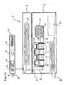
- the FIG. 2a shows a modular construction of a modular CHP according to the invention (2).
- the modular CHP is composed of a first module (6), a second module (8), a third module (10) and a fourth module (4), wherein the respective modules (4, 6, 8, 10) by means of connecting elements (12) are connected.
- the first module (6) has an internal combustion engine (16).
- the internal combustion engine (16) is connected via a shaft (18) to a generator (20).
- the generator (20) converts mechanical kinetic energy, in particular the rotational movement of the shaft (18) produced in the internal combustion engine (16).
- the internal combustion engine (16) points in the FIG. 2 Elements for heat transfer (22), which are with the at least one cooling circuit (24).
- the generator via a hydraulic connection (26), preferably an armored hose, connected to the at least one cooling circuit (24).
- the generator also has elements for heat transfer (22) which are connected to the at least one cooling circuit (24).
- the internal combustion engine (16) has elements of an exhaust system (28) which are connected to the at least one cooling circuit (24), in particular to the cooling circuit of the fourth module.
- the combustion gases of the engine can, in particular after their cooling via an exhaust nozzle (30) an external exhaust system, in particular a chimney (not shown), are supplied.
- the heat generated during operation of the CHP waste heat of the engine can be transmitted through the elements for heat transfer (22) to the at least one cooling circuit (24).
- the first module (6) Via a hydraulic connection (26), in particular via an armored hose, the first module (6) is connected to the second module (8) by means of connecting elements (12).
- the second module (8) has the at least one cooling circuit (24), which dissipates the waste heat of the internal combustion engine (16) via a, in particular fluid, coolant, preferably water.
- the heated coolant is supplied to a third module (10), in particular via a hydraulic connecting element (12).
- the third module (10) has means for measuring and counter (32), which preferably measure the fuel consumption and the amount of heat produced and / or derived. These counters (32) can be both analog and digital. Furthermore, the third module (10) has at least one controller, in particular a controller for at least one of the components, in particular the motor and / or the generator, or individual modules and / or the entire modular CHP and / or a connected heating system. This control can be adjusted via controls (34). Also, the third module (10) have a plurality of operating elements (34). The third module (10) preferably has at least one display (36) which preferably has touch-sensitive areas, in particular a touch pad. In a preferred embodiment, the third module has at least one inlet (38), in particular for the fuel of the engine (16), and / or a drain (40), in particular for the heated coolant, preferably water.
- the contact surfaces (14) between the modules (4, 6, 8, 10) may be designed so that the modules are positioned one above the other and / or interlock.
- the modules (4, 6, 8, 10) according to the invention can have installation profiles (42, 44), in particular pedestals (42) and / or support rails (44).
- the modules of the FIG. 2 are each connected to a directly adjacent connection module by means of a complementary connecting element (12).
- FIG. 2b shows a modular construction of a modular CHP according to the invention (2).
- This modular CHP consists of a first module, which also includes elements of an exhaust system (28) and elements of the at least one cooling circuit, and a second module.
- the Figure 2c shows an alternative construction of a modular CHP according to the invention (2). Deviating from the FIGS. 2a and 2 B For example, the controller for at least one of the components is locally remote from the first and second modules.
- FIG. 3a shows a preferred construction of a modular CHP (2).
- the modular CHP is also composed of a first module (6), a second module (8), a third module (10) and a fourth module (4).
- the first module (6) contains, in addition to the internal combustion engine (16), a generator (20). Both components are connected via at least one shaft (18).
- the internal combustion engine includes at least one heat transferred element (22) and an exhaust manifold (46) with a heat transferred element (22). These heat-transferred elements are each connected to the at least one cooling circuit (24), preferably with exactly one cooling circuit, in particular with a primary cooling circuit.
- the cooling circuit may have at least one pump (48).
- the internal combustion engine (16) is also connected via at least one supply line and at least one discharge with an oil tank and / or an oil reservoir extension (27).
- the oil tank (27) and / or the oil reservoir extension (27) is preferably housed in the fourth module.
- the fourth module can preferably also be an exhaust system (28), in particular with an exhaust damper and a heat exchanger (22) housed.
- the exhaust system (28) is preferably connected to an exhaust gas line (50), which runs in particular through all four modules (4, 6, 8, 10).
- an additional heat exchanger (22) in particular a condensing heat exchanger, preferably the waste heat of the exhaust gas by means of a Rohrbündel Anlagenübertragers (52) to the at least one cooling circuit (24), particularly preferably a second cooling circuit, in particular a secondary cooling circuit (24 ') transmits.
- This cooling circuit preferably the secondary cooling circuit, also has at least one pump (48), preferably at least two pumps.
- the at least one cooling circuit have at least one counter (32), preferably at least one heat meter.
- the third module (10) points in the FIG. 3 at least one control unit (54), which is preferably connected to a communication element (56).
- the communication element (56) may in particular have a transmitter and receiver for a data exchange.
- the third module may also include at least one counter (32).
- the gas line (58) have control elements (60) and / or counters.
- the third module preferably has all inflows (38) and / or outlets (40) and / or connections, in particular at least one connection to a low-voltage network (62) or to a chimney via an exhaust connection (30).
- the third module can in particular have at least one inlet (38) for a connectable heating network and / or have an inlet (38), preferably a second inlet, for a drinking water connection.
- the at least one cooling circuit in particular each circuit, preferably the cooling circuit, which is connected to the drinking water connection or the heating connection, in each case via a drain (40) via which in particular a warmed up in the CHP liquid, preferably heating water or drinking water, in a consumer network is fed.
- the third module also has a gas connection, that is to say an inlet (38) of the gas line (58).
- FIG. 3b is comparable with FIG. 2b .
- FIG. 4 shows a system (46) of CHP modules according to the invention (4, 6, 8, 10).
- the illustrated system has two first modules (6) which are each connected to a fourth module (4) and a, in particular common second module (8).
- the system includes a third module (10) containing at least one controller.
- the modules (4, 6, 8, 10) are interconnected by means of connecting elements (12).
Landscapes
- Engineering & Computer Science (AREA)
- Chemical & Material Sciences (AREA)
- Combustion & Propulsion (AREA)
- Mechanical Engineering (AREA)
- General Engineering & Computer Science (AREA)
- Physics & Mathematics (AREA)
- Thermal Sciences (AREA)
- Heat-Pump Type And Storage Water Heaters (AREA)
- Connection Of Motors, Electrical Generators, Mechanical Devices, And The Like (AREA)
- Exhaust Gas After Treatment (AREA)
- Engine Equipment That Uses Special Cycles (AREA)
Applications Claiming Priority (1)
| Application Number | Priority Date | Filing Date | Title |
|---|---|---|---|
| DE102009011475A DE102009011475B4 (de) | 2009-03-06 | 2009-03-06 | Modulares Blockheizkraftwerk |
Publications (3)
| Publication Number | Publication Date |
|---|---|
| EP2226574A2 true EP2226574A2 (fr) | 2010-09-08 |
| EP2226574A3 EP2226574A3 (fr) | 2013-11-13 |
| EP2226574B1 EP2226574B1 (fr) | 2019-07-24 |
Family
ID=42153912
Family Applications (1)
| Application Number | Title | Priority Date | Filing Date |
|---|---|---|---|
| EP10002358.9A Active EP2226574B1 (fr) | 2009-03-06 | 2010-03-08 | Centrale de chauffage en bloc modulaire |
Country Status (3)
| Country | Link |
|---|---|
| US (1) | US9267706B2 (fr) |
| EP (1) | EP2226574B1 (fr) |
| DE (1) | DE102009011475B4 (fr) |
Cited By (2)
| Publication number | Priority date | Publication date | Assignee | Title |
|---|---|---|---|---|
| CN104456690A (zh) * | 2012-11-05 | 2015-03-25 | 潘康苏尔特管理系统咨询有限公司 | 用于建筑物供热设备的热水供应装置 |
| EP3882535A1 (fr) * | 2020-03-20 | 2021-09-22 | EL-Björn AB | Appareil modulaire d'influence du climat intérieur |
Families Citing this family (13)
| Publication number | Priority date | Publication date | Assignee | Title |
|---|---|---|---|---|
| US9228760B2 (en) | 2012-04-27 | 2016-01-05 | Mac, Inc. | Flameless heating system |
| DE102013002047A1 (de) * | 2013-02-07 | 2014-08-07 | easykraft Energiezellen GmbH | Transportabler Energiecontainer |
| CN103727582A (zh) * | 2013-12-30 | 2014-04-16 | 陕西大唐新能电力设计有限公司 | 一种电厂采暖补水方法 |
| US20150361831A1 (en) * | 2014-06-12 | 2015-12-17 | General Electric Company | System and method for thermal management |
| DE102014220334A1 (de) * | 2014-10-07 | 2016-04-07 | Krones Aktiengesellschaft | Lebensmitteltechnische Prozessanlage, insbesondere Brauereianlage mit Blockheizkraft |
| DE102016103008B4 (de) * | 2016-02-22 | 2019-10-10 | SMART-NRGY GmbH & Co. KG | Energiezentrale und Betriebsverfahren |
| DE202017107001U1 (de) | 2017-11-18 | 2019-02-19 | Bdr Thermea Group B.V. | Blockheizkraftwerk |
| EP3787964A1 (fr) | 2018-04-30 | 2021-03-10 | Becker Marine Systems GmbH | Système modulaire d'alimentation électrique, dispositif d'alimentation électrique et procédé d'alimentation électrique d'une embarcation |
| RU2717182C1 (ru) * | 2019-08-23 | 2020-03-18 | Общество с ограниченной ответственностью Торговый дом "Кемеровский экспериментальный завод средств безопасности" | Модульный теплоэнергетический комплекс и способ нагрева шахтного воздуха, осуществляемый с его помощью |
| UA152186U (uk) * | 2022-08-17 | 2022-11-02 | Марійчин Андрій Васильович | Теплогенераторний комплекс |
| WO2023121613A1 (fr) | 2022-10-28 | 2023-06-29 | Panoteknik Jenerator Elektrik Sanayi Ve Ticaret Limited Sirketi | Système de gestion de dispositif de chauffage efficace portable pour générateurs de moteur diesel qui chauffe l'eau de bloc-moteur de manière économique avec la chaleur obtenue à partir d'une source de chaleur externe |
| DE202024102061U1 (de) * | 2024-04-24 | 2025-08-18 | Mehdi Eroglu | Trocknungssystem |
| US12463259B1 (en) | 2025-01-10 | 2025-11-04 | Enginuity Power Systems, Inc. | Integrated and compact combined heat and power systems and related methods |
Citations (2)
| Publication number | Priority date | Publication date | Assignee | Title |
|---|---|---|---|---|
| EP1030123A2 (fr) | 1999-02-16 | 2000-08-23 | Joh. Vaillant GmbH u. Co. | Groupe de chauffage et de puissance |
| DE102005002831A1 (de) | 2005-01-20 | 2006-08-03 | Alape Gmbh | Möbel zur Montage an einer Wand |
Family Cites Families (45)
| Publication number | Priority date | Publication date | Assignee | Title |
|---|---|---|---|---|
| US3025407A (en) * | 1957-08-19 | 1962-03-13 | American Air Filter Co | Portable heater |
| GB1345695A (en) * | 1970-03-20 | 1974-01-30 | Galt Equipment Ltd | Portable sel-contained heating unit |
| USRE30229E (en) | 1973-09-21 | 1980-03-11 | Robert L. Ziegelman | Modular operating centers and methods of building same for use in electric power generating plants and other industrial and commercial plants, processes and systems |
| IT7753376U1 (it) * | 1977-07-29 | 1979-01-29 | Fiat Spa | Apparato per la produzione combinata di energia elettrica e di vapore |
| DE3116624C2 (de) * | 1981-04-27 | 1985-08-29 | Daimler-Benz Ag, 7000 Stuttgart | Energieversorgungssystem für Wärme und Elektrizität |
| IT1155187B (it) * | 1982-05-07 | 1987-01-21 | Fiat Auto Spa | Apparatogeneratore modulare per la produzione combinata di energia elettrica e calore ed impianto comprendente una pluralita di tali apparati generatori |
| US5969435A (en) * | 1991-01-08 | 1999-10-19 | Nextek Power Systems, Inc. | Modular DC cogenerator systems |
| GB9114301D0 (en) * | 1991-07-02 | 1991-08-21 | Tilehouse Group Plc | Combined heat & power system |
| US5227957A (en) * | 1992-05-14 | 1993-07-13 | Deters John B | Modular computer system with passive backplane |
| US5517822A (en) * | 1993-06-15 | 1996-05-21 | Applied Energy Systems Of Oklahoma, Inc. | Mobile congeneration apparatus including inventive valve and boiler |
| US5737189A (en) * | 1994-01-10 | 1998-04-07 | Artecon | High performance mass storage subsystem |
| US6377874B1 (en) * | 1994-09-07 | 2002-04-23 | Spd Technologies Inc. | Power distribution system including integrated power node control center |
| US5981101A (en) * | 1997-06-02 | 1999-11-09 | Gnb Technologies, Inc. | Modular cell tray assembly for sealed lead-acid cells |
| US5977644A (en) * | 1997-08-26 | 1999-11-02 | Lucent Technologies Inc. | Backup power system having improved cooling airflow and method of operation thereof |
| US6053418A (en) * | 1998-01-14 | 2000-04-25 | Yankee Scientific, Inc. | Small-scale cogeneration system for producing heat and electrical power |
| US6094130A (en) * | 1998-04-15 | 2000-07-25 | Uischner; Charles W. | Emergency power station for traffic control signals |
| US6329907B1 (en) * | 1998-04-15 | 2001-12-11 | Charles W. Uischner | Emergency power system for traffic control signals |
| US6441505B1 (en) * | 1998-12-11 | 2002-08-27 | Qwest Communications International, Inc. | Stacked cabinet backup generator |
| US6250080B1 (en) * | 1999-06-24 | 2001-06-26 | Wartsila Nsd North America, Inc. | Mobile modular intermodal cogeneration system |
| NL1015319C2 (nl) * | 2000-05-26 | 2001-11-27 | Enatec Micro Cogen B V | Inrichting en werkwijze voor het gekoppeld opwekken van warmte en elektriciteit. |
| US6644410B1 (en) * | 2000-07-27 | 2003-11-11 | Christopher John Lindsey-Curran | Modular subsea control system |
| CN1474931A (zh) * | 2000-11-24 | 2004-02-11 | 用于建造工业设备的模块式系统 | |
| US6736658B2 (en) * | 2000-12-05 | 2004-05-18 | Henry Milan | Power supply interconnecting device |
| US6661648B2 (en) * | 2001-07-03 | 2003-12-09 | Hewlett-Packard Development Company, Lp. | Modular processor based apparatus |
| WO2003057533A1 (fr) * | 2001-12-28 | 2003-07-17 | Brackmann Rogers F | Systeme prive d'expedition de marchandises par caisses-palettes |
| US7053497B2 (en) * | 2003-02-10 | 2006-05-30 | Briggs & Stratton Power Products Group, Llc | Monitoring system for a generator |
| US7040544B2 (en) * | 2003-11-07 | 2006-05-09 | Climate Energy, Llc | System and method for warm air space heating with electrical power generation |
| US7174260B2 (en) | 2004-04-01 | 2007-02-06 | Blue Line Innovations Inc. | System and method for reading power meters |
| EP1607586A1 (fr) | 2004-05-06 | 2005-12-21 | Siemens Aktiengesellschaft | Centrale à vapeur |
| ITTO20040579A1 (it) * | 2004-08-31 | 2004-11-30 | Itw Welding Products Italy Srl | Macchina saldatrice e relativo metodo di funzionamento |
| US7377113B2 (en) * | 2004-12-06 | 2008-05-27 | John Scalone | Modular turbine generator and method of operation |
| US20060119104A1 (en) * | 2004-12-07 | 2006-06-08 | Wall Jerrold R | Portable wind up DC generator |
| US7690202B2 (en) * | 2005-05-16 | 2010-04-06 | General Electric Company | Mobile gas turbine engine and generator assembly |
| ITTV20050171A1 (it) * | 2005-11-08 | 2007-05-09 | Termotecniche Fraccaro O T F S | Dispositivo per il riscaldamento, la produzione di energia elettrica ed il raffrescamento di locali. |
| EP1853098A3 (fr) * | 2006-05-03 | 2013-07-10 | Parker-Hannifin Corporation | Système et procédé d'empilage modulaire à commande haute puissance |
| EP1881177B1 (fr) * | 2006-07-21 | 2012-05-16 | C.R.F. Società Consortile per Azioni | Système de génération d'énergie modulaire |
| NL1032598C2 (nl) * | 2006-09-29 | 2009-02-25 | Kamstrup B V | Inrichting, systeem en werkwijze voor het besturen van een verwarmingssysteem. |
| US7960943B2 (en) * | 2006-11-17 | 2011-06-14 | Cobasys, Llc | Modular battery system having battery monitoring and data collection capability |
| DE202007008712U1 (de) * | 2007-06-19 | 2007-09-27 | RES - Rationelle Energie Süd GmbH | Stromerzeugende Heizung |
| US20090058098A1 (en) * | 2007-08-13 | 2009-03-05 | Michael Patrick Flynn | Backup generators |
| US8159078B2 (en) * | 2008-04-21 | 2012-04-17 | Black & Decker Inc. | Portable power driven equipment with internal combustion engine combined battery charging and starting circuit where the battery is a removable battery pack |
| US9124144B2 (en) * | 2008-05-21 | 2015-09-01 | Bryan Prucher | Dual radial gap motor-generator structure |
| US8046961B1 (en) * | 2008-05-27 | 2011-11-01 | Solarcraft, Inc. | Tactical solar power system |
| US8567354B2 (en) * | 2008-07-17 | 2013-10-29 | Clear Energy Systems, Inc. | Portable energy generation systems |
| FR2948990A1 (fr) * | 2009-08-04 | 2011-02-11 | Mobile Comfort Holding | Dispositif thermodynamique multi-energie modulaire |
-
2009
- 2009-03-06 DE DE102009011475A patent/DE102009011475B4/de not_active Expired - Fee Related
-
2010
- 2010-03-08 EP EP10002358.9A patent/EP2226574B1/fr active Active
- 2010-03-08 US US12/719,187 patent/US9267706B2/en not_active Expired - Fee Related
Patent Citations (3)
| Publication number | Priority date | Publication date | Assignee | Title |
|---|---|---|---|---|
| EP1030123A2 (fr) | 1999-02-16 | 2000-08-23 | Joh. Vaillant GmbH u. Co. | Groupe de chauffage et de puissance |
| EP1030123B1 (fr) | 1999-02-16 | 2005-11-16 | Vaillant GmbH | Groupe de chauffage et de puissance |
| DE102005002831A1 (de) | 2005-01-20 | 2006-08-03 | Alape Gmbh | Möbel zur Montage an einer Wand |
Cited By (3)
| Publication number | Priority date | Publication date | Assignee | Title |
|---|---|---|---|---|
| CN104456690A (zh) * | 2012-11-05 | 2015-03-25 | 潘康苏尔特管理系统咨询有限公司 | 用于建筑物供热设备的热水供应装置 |
| CN104456690B (zh) * | 2012-11-05 | 2019-07-26 | 潘康苏尔特管理系统咨询有限公司 | 用于建筑物供热设备的热水供应装置 |
| EP3882535A1 (fr) * | 2020-03-20 | 2021-09-22 | EL-Björn AB | Appareil modulaire d'influence du climat intérieur |
Also Published As
| Publication number | Publication date |
|---|---|
| US9267706B2 (en) | 2016-02-23 |
| US20100224689A1 (en) | 2010-09-09 |
| EP2226574B1 (fr) | 2019-07-24 |
| EP2226574A3 (fr) | 2013-11-13 |
| DE102009011475B4 (de) | 2012-05-16 |
| DE102009011475A1 (de) | 2010-12-09 |
Similar Documents
| Publication | Publication Date | Title |
|---|---|---|
| DE102009011475B4 (de) | Modulares Blockheizkraftwerk | |
| DE202009006294U1 (de) | Vorrichtung zur Beheizung und/oder Stromversorgung eines Gebäudes | |
| AT508737A2 (de) | Vorrichtung zur wärmeregelung | |
| EP1967659A2 (fr) | Système de transmission d'eau | |
| EP0940637B1 (fr) | Installation de production d'énergie compacte | |
| DE102016103008B4 (de) | Energiezentrale und Betriebsverfahren | |
| DE19829192B4 (de) | Energie-Kompakt-Anlage | |
| EP1895139B1 (fr) | Système d'alimentation en énergie | |
| EP2116789A2 (fr) | Centrale de chauffage compacte | |
| DE10111072B4 (de) | Anlage zur Erzeugung von Strom und Wärme | |
| AT3519U1 (de) | Verfahren zur herstellung von gebäuden | |
| WO2005093236A1 (fr) | Centrale mobile | |
| DE20103062U1 (de) | Verteilerstation für eine Heizungs- und Wasserversorgungsanlage | |
| DE212013000132U1 (de) | Kesselanlagen-System sowie Komponenten und Bauteile dieses Systems | |
| DE102008019614A1 (de) | Stromerzeugende Heizung | |
| DE102012018797B4 (de) | Wärmeenergieversorgungsanlage und Verfahren zu deren Betrieb | |
| EP2564036A2 (fr) | Système de couplage pour une installation à énergie hybride | |
| CN203323237U (zh) | 可移动箱式换热机组 | |
| DE102021110031A1 (de) | Dezentrale Energieeinheit | |
| DE202021102117U1 (de) | Dezentrale Energieeinheit | |
| DE102009049344A1 (de) | Hydraulische Anbindung für Kraft-Wärme-Kopplungsanlagen | |
| EP4321696A1 (fr) | Unité modulaire | |
| DE102022133542A1 (de) | Betriebseinheit zum kombinierbaren fluidgestützten Wärmebetrieb einer Heizungsanlage mit Wärme aus unterschiedlichen Wärmeerzeugereinheiten | |
| DE202022002744U1 (de) | Betriebseinheit zum kombinierbaren fluidgestützten Wärmebetrieb einer Heizungsanlage mit Wärme aus unterschiedlichen Wärmeerzeugereinheiten | |
| DE202007011607U1 (de) | Wohnungsversorgungsstation |
Legal Events
| Date | Code | Title | Description |
|---|---|---|---|
| PUAI | Public reference made under article 153(3) epc to a published international application that has entered the european phase |
Free format text: ORIGINAL CODE: 0009012 |
|
| AK | Designated contracting states |
Kind code of ref document: A2 Designated state(s): AT BE BG CH CY CZ DE DK EE ES FI FR GB GR HR HU IE IS IT LI LT LU LV MC MK MT NL NO PL PT RO SE SI SK SM TR |
|
| AX | Request for extension of the european patent |
Extension state: AL BA ME RS |
|
| PUAL | Search report despatched |
Free format text: ORIGINAL CODE: 0009013 |
|
| AK | Designated contracting states |
Kind code of ref document: A3 Designated state(s): AT BE BG CH CY CZ DE DK EE ES FI FR GB GR HR HU IE IS IT LI LT LU LV MC MK MT NL NO PL PT RO SE SI SK SM TR |
|
| AX | Request for extension of the european patent |
Extension state: AL BA ME RS |
|
| RIC1 | Information provided on ipc code assigned before grant |
Ipc: F24D 19/10 20060101AFI20131010BHEP Ipc: F24H 9/02 20060101ALI20131010BHEP Ipc: F24H 9/06 20060101ALI20131010BHEP Ipc: F24H 9/14 20060101ALI20131010BHEP |
|
| 17P | Request for examination filed |
Effective date: 20140423 |
|
| RBV | Designated contracting states (corrected) |
Designated state(s): AT BE BG CH CY CZ DE DK EE ES FI FR GB GR HR HU IE IS IT LI LT LU LV MC MK MT NL NO PL PT RO SE SI SK SM TR |
|
| 17Q | First examination report despatched |
Effective date: 20140925 |
|
| STAA | Information on the status of an ep patent application or granted ep patent |
Free format text: STATUS: EXAMINATION IS IN PROGRESS |
|
| TPAC | Observations filed by third parties |
Free format text: ORIGINAL CODE: EPIDOSNTIPA |
|
| GRAP | Despatch of communication of intention to grant a patent |
Free format text: ORIGINAL CODE: EPIDOSNIGR1 |
|
| STAA | Information on the status of an ep patent application or granted ep patent |
Free format text: STATUS: GRANT OF PATENT IS INTENDED |
|
| INTG | Intention to grant announced |
Effective date: 20190222 |
|
| GRAS | Grant fee paid |
Free format text: ORIGINAL CODE: EPIDOSNIGR3 |
|
| GRAA | (expected) grant |
Free format text: ORIGINAL CODE: 0009210 |
|
| STAA | Information on the status of an ep patent application or granted ep patent |
Free format text: STATUS: THE PATENT HAS BEEN GRANTED |
|
| GRAT | Correction requested after decision to grant or after decision to maintain patent in amended form |
Free format text: ORIGINAL CODE: EPIDOSNCDEC |
|
| AK | Designated contracting states |
Kind code of ref document: B1 Designated state(s): AT BE BG CH CY CZ DE DK EE ES FI FR GB GR HR HU IE IS IT LI LT LU LV MC MK MT NL NO PL PT RO SE SI SK SM TR |
|
| REG | Reference to a national code |
Ref country code: GB Ref legal event code: FG4D Free format text: NOT ENGLISH |
|
| REG | Reference to a national code |
Ref country code: CH Ref legal event code: EP |
|
| REG | Reference to a national code |
Ref country code: DE Ref legal event code: R096 Ref document number: 502010016144 Country of ref document: DE |
|
| REG | Reference to a national code |
Ref country code: CH Ref legal event code: NV Representative=s name: RENTSCH PARTNER AG, CH Ref country code: AT Ref legal event code: REF Ref document number: 1158655 Country of ref document: AT Kind code of ref document: T Effective date: 20190815 |
|
| REG | Reference to a national code |
Ref country code: IE Ref legal event code: FG4D Free format text: LANGUAGE OF EP DOCUMENT: GERMAN |
|
| REG | Reference to a national code |
Ref country code: NL Ref legal event code: MP Effective date: 20190724 |
|
| REG | Reference to a national code |
Ref country code: LT Ref legal event code: MG4D |
|
| PG25 | Lapsed in a contracting state [announced via postgrant information from national office to epo] |
Ref country code: SE Free format text: LAPSE BECAUSE OF FAILURE TO SUBMIT A TRANSLATION OF THE DESCRIPTION OR TO PAY THE FEE WITHIN THE PRESCRIBED TIME-LIMIT Effective date: 20190724 Ref country code: BG Free format text: LAPSE BECAUSE OF FAILURE TO SUBMIT A TRANSLATION OF THE DESCRIPTION OR TO PAY THE FEE WITHIN THE PRESCRIBED TIME-LIMIT Effective date: 20191024 Ref country code: PT Free format text: LAPSE BECAUSE OF FAILURE TO SUBMIT A TRANSLATION OF THE DESCRIPTION OR TO PAY THE FEE WITHIN THE PRESCRIBED TIME-LIMIT Effective date: 20191125 Ref country code: NL Free format text: LAPSE BECAUSE OF FAILURE TO SUBMIT A TRANSLATION OF THE DESCRIPTION OR TO PAY THE FEE WITHIN THE PRESCRIBED TIME-LIMIT Effective date: 20190724 Ref country code: LT Free format text: LAPSE BECAUSE OF FAILURE TO SUBMIT A TRANSLATION OF THE DESCRIPTION OR TO PAY THE FEE WITHIN THE PRESCRIBED TIME-LIMIT Effective date: 20190724 Ref country code: HR Free format text: LAPSE BECAUSE OF FAILURE TO SUBMIT A TRANSLATION OF THE DESCRIPTION OR TO PAY THE FEE WITHIN THE PRESCRIBED TIME-LIMIT Effective date: 20190724 Ref country code: FI Free format text: LAPSE BECAUSE OF FAILURE TO SUBMIT A TRANSLATION OF THE DESCRIPTION OR TO PAY THE FEE WITHIN THE PRESCRIBED TIME-LIMIT Effective date: 20190724 Ref country code: NO Free format text: LAPSE BECAUSE OF FAILURE TO SUBMIT A TRANSLATION OF THE DESCRIPTION OR TO PAY THE FEE WITHIN THE PRESCRIBED TIME-LIMIT Effective date: 20191024 |
|
| PG25 | Lapsed in a contracting state [announced via postgrant information from national office to epo] |
Ref country code: LV Free format text: LAPSE BECAUSE OF FAILURE TO SUBMIT A TRANSLATION OF THE DESCRIPTION OR TO PAY THE FEE WITHIN THE PRESCRIBED TIME-LIMIT Effective date: 20190724 Ref country code: GR Free format text: LAPSE BECAUSE OF FAILURE TO SUBMIT A TRANSLATION OF THE DESCRIPTION OR TO PAY THE FEE WITHIN THE PRESCRIBED TIME-LIMIT Effective date: 20191025 Ref country code: IS Free format text: LAPSE BECAUSE OF FAILURE TO SUBMIT A TRANSLATION OF THE DESCRIPTION OR TO PAY THE FEE WITHIN THE PRESCRIBED TIME-LIMIT Effective date: 20191124 Ref country code: ES Free format text: LAPSE BECAUSE OF FAILURE TO SUBMIT A TRANSLATION OF THE DESCRIPTION OR TO PAY THE FEE WITHIN THE PRESCRIBED TIME-LIMIT Effective date: 20190724 |
|
| REG | Reference to a national code |
Ref country code: CH Ref legal event code: PUE Owner name: VOLKSWAGEN AG, DE Free format text: FORMER OWNER: LICHTBLICK ZUHAUSEKRAFTWERK GMBH, DE |
|
| PG25 | Lapsed in a contracting state [announced via postgrant information from national office to epo] |
Ref country code: TR Free format text: LAPSE BECAUSE OF FAILURE TO SUBMIT A TRANSLATION OF THE DESCRIPTION OR TO PAY THE FEE WITHIN THE PRESCRIBED TIME-LIMIT Effective date: 20190724 |
|
| PG25 | Lapsed in a contracting state [announced via postgrant information from national office to epo] |
Ref country code: DK Free format text: LAPSE BECAUSE OF FAILURE TO SUBMIT A TRANSLATION OF THE DESCRIPTION OR TO PAY THE FEE WITHIN THE PRESCRIBED TIME-LIMIT Effective date: 20190724 Ref country code: EE Free format text: LAPSE BECAUSE OF FAILURE TO SUBMIT A TRANSLATION OF THE DESCRIPTION OR TO PAY THE FEE WITHIN THE PRESCRIBED TIME-LIMIT Effective date: 20190724 Ref country code: RO Free format text: LAPSE BECAUSE OF FAILURE TO SUBMIT A TRANSLATION OF THE DESCRIPTION OR TO PAY THE FEE WITHIN THE PRESCRIBED TIME-LIMIT Effective date: 20190724 Ref country code: IT Free format text: LAPSE BECAUSE OF FAILURE TO SUBMIT A TRANSLATION OF THE DESCRIPTION OR TO PAY THE FEE WITHIN THE PRESCRIBED TIME-LIMIT Effective date: 20190724 Ref country code: PL Free format text: LAPSE BECAUSE OF FAILURE TO SUBMIT A TRANSLATION OF THE DESCRIPTION OR TO PAY THE FEE WITHIN THE PRESCRIBED TIME-LIMIT Effective date: 20190724 |
|
| PGFP | Annual fee paid to national office [announced via postgrant information from national office to epo] |
Ref country code: DE Payment date: 20200320 Year of fee payment: 11 Ref country code: AT Payment date: 20200325 Year of fee payment: 11 |
|
| REG | Reference to a national code |
Ref legal event code: R082 Ref document number: 502010016144 Ref country code: DE Ref legal event code: R082 Ref document number: 502010016144 Country of ref document: DE Representative=s name: NEUBAUER LIEBL BIERSCHNEIDER MASSINGER, DE Ref country code: DE Ref legal event code: R081 Ref document number: 502010016144 Country of ref document: DE Owner name: VOLKSWAGEN AKTIENGESELLSCHAFT, DE Free format text: FORMER OWNER: LICHTBLICK ZUHAUSEKRAFTWERK GMBH, 20359 HAMBURG, DE |
|
| PG25 | Lapsed in a contracting state [announced via postgrant information from national office to epo] |
Ref country code: SM Free format text: LAPSE BECAUSE OF FAILURE TO SUBMIT A TRANSLATION OF THE DESCRIPTION OR TO PAY THE FEE WITHIN THE PRESCRIBED TIME-LIMIT Effective date: 20190724 Ref country code: IS Free format text: LAPSE BECAUSE OF FAILURE TO SUBMIT A TRANSLATION OF THE DESCRIPTION OR TO PAY THE FEE WITHIN THE PRESCRIBED TIME-LIMIT Effective date: 20200224 Ref country code: SK Free format text: LAPSE BECAUSE OF FAILURE TO SUBMIT A TRANSLATION OF THE DESCRIPTION OR TO PAY THE FEE WITHIN THE PRESCRIBED TIME-LIMIT Effective date: 20190724 Ref country code: CZ Free format text: LAPSE BECAUSE OF FAILURE TO SUBMIT A TRANSLATION OF THE DESCRIPTION OR TO PAY THE FEE WITHIN THE PRESCRIBED TIME-LIMIT Effective date: 20190724 |
|
| PGFP | Annual fee paid to national office [announced via postgrant information from national office to epo] |
Ref country code: CH Payment date: 20200319 Year of fee payment: 11 |
|
| REG | Reference to a national code |
Ref country code: DE Ref legal event code: R097 Ref document number: 502010016144 Country of ref document: DE |
|
| RAP2 | Party data changed (patent owner data changed or rights of a patent transferred) |
Owner name: VOLKSWAGEN AG |
|
| PLBE | No opposition filed within time limit |
Free format text: ORIGINAL CODE: 0009261 |
|
| STAA | Information on the status of an ep patent application or granted ep patent |
Free format text: STATUS: NO OPPOSITION FILED WITHIN TIME LIMIT |
|
| PG2D | Information on lapse in contracting state deleted |
Ref country code: IS |
|
| 26N | No opposition filed |
Effective date: 20200603 |
|
| PG25 | Lapsed in a contracting state [announced via postgrant information from national office to epo] |
Ref country code: SI Free format text: LAPSE BECAUSE OF FAILURE TO SUBMIT A TRANSLATION OF THE DESCRIPTION OR TO PAY THE FEE WITHIN THE PRESCRIBED TIME-LIMIT Effective date: 20190724 |
|
| REG | Reference to a national code |
Ref country code: AT Ref legal event code: PC Ref document number: 1158655 Country of ref document: AT Kind code of ref document: T Owner name: VOLKSWAGEN AG, DE Effective date: 20200722 |
|
| PG25 | Lapsed in a contracting state [announced via postgrant information from national office to epo] |
Ref country code: MC Free format text: LAPSE BECAUSE OF FAILURE TO SUBMIT A TRANSLATION OF THE DESCRIPTION OR TO PAY THE FEE WITHIN THE PRESCRIBED TIME-LIMIT Effective date: 20190724 |
|
| REG | Reference to a national code |
Ref country code: BE Ref legal event code: MM Effective date: 20200331 |
|
| PG25 | Lapsed in a contracting state [announced via postgrant information from national office to epo] |
Ref country code: LU Free format text: LAPSE BECAUSE OF NON-PAYMENT OF DUE FEES Effective date: 20200308 |
|
| PG25 | Lapsed in a contracting state [announced via postgrant information from national office to epo] |
Ref country code: IE Free format text: LAPSE BECAUSE OF NON-PAYMENT OF DUE FEES Effective date: 20200308 Ref country code: FR Free format text: LAPSE BECAUSE OF NON-PAYMENT OF DUE FEES Effective date: 20200331 |
|
| REG | Reference to a national code |
Ref country code: DE Ref legal event code: R082 Ref document number: 502010016144 Country of ref document: DE |
|
| PG25 | Lapsed in a contracting state [announced via postgrant information from national office to epo] |
Ref country code: BE Free format text: LAPSE BECAUSE OF NON-PAYMENT OF DUE FEES Effective date: 20200331 |
|
| GBPC | Gb: european patent ceased through non-payment of renewal fee |
Effective date: 20200308 |
|
| PG25 | Lapsed in a contracting state [announced via postgrant information from national office to epo] |
Ref country code: GB Free format text: LAPSE BECAUSE OF NON-PAYMENT OF DUE FEES Effective date: 20200308 |
|
| REG | Reference to a national code |
Ref country code: DE Ref legal event code: R119 Ref document number: 502010016144 Country of ref document: DE |
|
| REG | Reference to a national code |
Ref country code: CH Ref legal event code: PL |
|
| REG | Reference to a national code |
Ref country code: AT Ref legal event code: MM01 Ref document number: 1158655 Country of ref document: AT Kind code of ref document: T Effective date: 20210308 |
|
| PG25 | Lapsed in a contracting state [announced via postgrant information from national office to epo] |
Ref country code: CH Free format text: LAPSE BECAUSE OF NON-PAYMENT OF DUE FEES Effective date: 20210331 Ref country code: AT Free format text: LAPSE BECAUSE OF NON-PAYMENT OF DUE FEES Effective date: 20210308 Ref country code: LI Free format text: LAPSE BECAUSE OF NON-PAYMENT OF DUE FEES Effective date: 20210331 Ref country code: DE Free format text: LAPSE BECAUSE OF NON-PAYMENT OF DUE FEES Effective date: 20211001 |
|
| PG25 | Lapsed in a contracting state [announced via postgrant information from national office to epo] |
Ref country code: MT Free format text: LAPSE BECAUSE OF FAILURE TO SUBMIT A TRANSLATION OF THE DESCRIPTION OR TO PAY THE FEE WITHIN THE PRESCRIBED TIME-LIMIT Effective date: 20190724 Ref country code: CY Free format text: LAPSE BECAUSE OF FAILURE TO SUBMIT A TRANSLATION OF THE DESCRIPTION OR TO PAY THE FEE WITHIN THE PRESCRIBED TIME-LIMIT Effective date: 20190724 |
|
| PG25 | Lapsed in a contracting state [announced via postgrant information from national office to epo] |
Ref country code: MK Free format text: LAPSE BECAUSE OF FAILURE TO SUBMIT A TRANSLATION OF THE DESCRIPTION OR TO PAY THE FEE WITHIN THE PRESCRIBED TIME-LIMIT Effective date: 20190724 |