EP2226745A1 - Vorrichtung und Verfahren zum Erhalten eines zufälligen Codes, der in einer Vorrichtung zur einzigartigen Identifizierung eines Produkts benutzt werden kann - Google Patents
Vorrichtung und Verfahren zum Erhalten eines zufälligen Codes, der in einer Vorrichtung zur einzigartigen Identifizierung eines Produkts benutzt werden kann Download PDFInfo
- Publication number
- EP2226745A1 EP2226745A1 EP10155485A EP10155485A EP2226745A1 EP 2226745 A1 EP2226745 A1 EP 2226745A1 EP 10155485 A EP10155485 A EP 10155485A EP 10155485 A EP10155485 A EP 10155485A EP 2226745 A1 EP2226745 A1 EP 2226745A1
- Authority
- EP
- European Patent Office
- Prior art keywords
- random
- obtaining
- layer
- code
- continuous strip
- Prior art date
- Legal status (The legal status is an assumption and is not a legal conclusion. Google has not performed a legal analysis and makes no representation as to the accuracy of the status listed.)
- Withdrawn
Links
Images


Classifications
-
- B—PERFORMING OPERATIONS; TRANSPORTING
- B42—BOOKBINDING; ALBUMS; FILES; SPECIAL PRINTED MATTER
- B42D—BOOKS; BOOK COVERS; LOOSE LEAVES; PRINTED MATTER CHARACTERISED BY IDENTIFICATION OR SECURITY FEATURES; PRINTED MATTER OF SPECIAL FORMAT OR STYLE NOT OTHERWISE PROVIDED FOR; DEVICES FOR USE THEREWITH AND NOT OTHERWISE PROVIDED FOR; MOVABLE-STRIP WRITING OR READING APPARATUS
- B42D25/00—Information-bearing cards or sheet-like structures characterised by identification or security features; Manufacture thereof
- B42D25/30—Identification or security features, e.g. for preventing forgery
- B42D25/346—Perforations
-
- G—PHYSICS
- G06—COMPUTING OR CALCULATING; COUNTING
- G06K—GRAPHICAL DATA READING; PRESENTATION OF DATA; RECORD CARRIERS; HANDLING RECORD CARRIERS
- G06K19/00—Record carriers for use with machines and with at least a part designed to carry digital markings
- G06K19/06—Record carriers for use with machines and with at least a part designed to carry digital markings characterised by the kind of the digital marking, e.g. shape, nature, code
-
- B—PERFORMING OPERATIONS; TRANSPORTING
- B42—BOOKBINDING; ALBUMS; FILES; SPECIAL PRINTED MATTER
- B42D—BOOKS; BOOK COVERS; LOOSE LEAVES; PRINTED MATTER CHARACTERISED BY IDENTIFICATION OR SECURITY FEATURES; PRINTED MATTER OF SPECIAL FORMAT OR STYLE NOT OTHERWISE PROVIDED FOR; DEVICES FOR USE THEREWITH AND NOT OTHERWISE PROVIDED FOR; MOVABLE-STRIP WRITING OR READING APPARATUS
- B42D25/00—Information-bearing cards or sheet-like structures characterised by identification or security features; Manufacture thereof
- B42D25/20—Information-bearing cards or sheet-like structures characterised by identification or security features; Manufacture thereof characterised by a particular use or purpose
- B42D25/29—Securities; Bank notes
-
- B—PERFORMING OPERATIONS; TRANSPORTING
- B42—BOOKBINDING; ALBUMS; FILES; SPECIAL PRINTED MATTER
- B42D—BOOKS; BOOK COVERS; LOOSE LEAVES; PRINTED MATTER CHARACTERISED BY IDENTIFICATION OR SECURITY FEATURES; PRINTED MATTER OF SPECIAL FORMAT OR STYLE NOT OTHERWISE PROVIDED FOR; DEVICES FOR USE THEREWITH AND NOT OTHERWISE PROVIDED FOR; MOVABLE-STRIP WRITING OR READING APPARATUS
- B42D25/00—Information-bearing cards or sheet-like structures characterised by identification or security features; Manufacture thereof
- B42D25/40—Manufacture
- B42D25/405—Marking
- B42D25/43—Marking by removal of material
-
- G—PHYSICS
- G06—COMPUTING OR CALCULATING; COUNTING
- G06K—GRAPHICAL DATA READING; PRESENTATION OF DATA; RECORD CARRIERS; HANDLING RECORD CARRIERS
- G06K19/00—Record carriers for use with machines and with at least a part designed to carry digital markings
- G06K19/06—Record carriers for use with machines and with at least a part designed to carry digital markings characterised by the kind of the digital marking, e.g. shape, nature, code
- G06K19/08—Record carriers for use with machines and with at least a part designed to carry digital markings characterised by the kind of the digital marking, e.g. shape, nature, code using markings of different kinds or more than one marking of the same kind in the same record carrier, e.g. one marking being sensed by optical and the other by magnetic means
- G06K19/083—Constructional details
- G06K19/086—Constructional details with markings consisting of randomly placed or oriented elements, the randomness of the elements being useable for generating a unique identifying signature of the record carrier, e.g. randomly placed magnetic fibers or magnetic particles in the body of a credit card
-
- B42D2033/22—
-
- B42D2035/34—
-
- B—PERFORMING OPERATIONS; TRANSPORTING
- B42—BOOKBINDING; ALBUMS; FILES; SPECIAL PRINTED MATTER
- B42D—BOOKS; BOOK COVERS; LOOSE LEAVES; PRINTED MATTER CHARACTERISED BY IDENTIFICATION OR SECURITY FEATURES; PRINTED MATTER OF SPECIAL FORMAT OR STYLE NOT OTHERWISE PROVIDED FOR; DEVICES FOR USE THEREWITH AND NOT OTHERWISE PROVIDED FOR; MOVABLE-STRIP WRITING OR READING APPARATUS
- B42D25/00—Information-bearing cards or sheet-like structures characterised by identification or security features; Manufacture thereof
- B42D25/40—Manufacture
- B42D25/45—Associating two or more layers
Definitions
- the present invention refers to a method and to an apparatus for obtaining a random code useable in a device for unique identification of a product as well as a device obtained by means of the same.
- the presence and authenticity of the devices for identifying products is thus verifiable by the dealers and by the end purchasers when purchasing goods or even at a later stage, possibly being able to track back to the supplier of the counterfeited goods in case the identification device is not authentic.
- the reliability offered by the devices for identifying products is strictly linked to the reproducibility of the same by the counterfeiter.
- identification devices which comprise a perforated membrane, where the space distribution of the holes obtained on the same defines a code.
- the membranes are perforated defining - ex ante - a random distribution of microholes identifying a code and reproducing such distribution by obtaining microholes on the membrane through a controlled spatial displacement of suitable means for engraving or removing material.
- engraving means is the laser which is driven by means of a microprocessor in such a manner to reproduce the shape and positioning of each and every hole.
- photosensitive masks designed using electronic processing means according to the codes to be reproduced and subsequently used for the selective removal of material by using suitable acids.
- a discrete positioning, just like the discrete shape of the holes provide a finite number, no matter how large it is, of combinations which can thus be calculated and foreseen by means that reproduce the code.
- a perforated member thus obtained is thus easily reproducible through electronic detection of the positioning and of the discrete shapes of the holes before driving analogous engraving or removal means in such a manner to reproduce the positions and shapes in an identical manner.
- the perforated membrane devices for identifying a product obtained through the currently known apparatus are thus reproducible in an identical manner without the possibility of distinction between an authentic device and a counterfeit device.
- An object of the present invention is that of overcoming the abovementioned drawbacks and in particular that of providing an apparatus and a method for obtaining a random code useable in a device for unique identification of a product capable of obtaining an identification device not reproducible identically.
- Another object of the present invention is that of providing an apparatus and a method for obtaining a random code useable in a device for unique identification of a product having a non-identically reproducible code.
- an object of the present invention is that of obtaining a random code useable in a device for unique identification of a product which, though offering high degree of reliability, may be obtained in a simple manner.
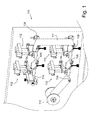
- FIG. 1 shown is an apparatus for obtaining a random code useable in a device 10 for unique identification of a product, indicated in its entirety with 110.
- the apparatus 110 comprises a sliding path of a continuous strip 111, preferably made of polymer material, arranged along which is at least one drilling station 112 for obtaining a plurality of holes on the strip 111.
- the sliding path may be delimited by a first roller 113 for unwinding the continuous strip 111 and a second roller 114 for winding such strip 111 once perforated.
- the sliding path may comprise a plurality of deviation and tensioning rollers 109 suitable to impose a determined path to the continuous strip 111.
- the drilling station 112 is of the random type i.e. it is capable of generating a plurality of holes according to a random and irreproducible process.
- the random drilling station 112 comprises at least one means 115,117,118 for generating an electrical discharge towards the continuous strip 111 passing by.
- Each electrical discharge makes a hole in the continuous strip 111, the hole generally measuring between 0.5 mm and 2 mm, distributed randomly and of any shape and generally irregular.
- the distribution is entirely random being linked to the random and irreproducible process of the ionisation of the molecules in the air for defining a discharge trajectory.
- discharge paths that are created are thus always different and deterministically non-reproducible, i.e. through discrete processes, for example implemented through numerical control machines.
- the at least one means 115,117,118 for generating an electrical discharge comprises at least one sphere made of material having good electrical conduction 115 properties, for example metal, supported suspended and facing a metal support 116 substantially flat, sliding on which is the continuous strip 111.
- Applied between the metal sphere 115 and the flat support 116 is a potential difference sufficient for generating electrical discharges between the two elements 115,116.
- the flat support 116 is connected to the earth, while the metal sphere 115 is connected to a source of voltage through a driving circuit 106 suitable to impart to the metal sphere 15 a voltage wave with peak values sufficient to generate electrical discharges.
- the voltage wave is made up of linear rising and falling fronts with peak values comprised between 8 kV and 25 kV and a frequency such to generate 20-40 discharges per second.
- FIG. 3 An example of a driving circuit 106 is illustrated in figure 3 .
- the flat support 116 is preferably adjustable moving away from and nearing towards at least one metal sphere 115 with the aim of adjusting to the available peak value.
- an adjustment screw 108 coupled rotatingly to a fixed element 107 and to the flat support 116 in such a manner to translate with respect to the fixed element 107 and impart a vertical translation to the flat support 116 when actuated in rotation.
- At least one metal sphere 115 is moveable on a plane parallel to the flat support 116 with the aim of distributing electrical discharges along the movement path thereof.
- the metal sphere 115 is for example supported rotatingly around a rotation axis A by a connection rod 118, preferably coated with insulating material, and driven in rotation by means of an actuator 117.
- the at least one means 115,117,118 for generating an electrical discharge of the drilling station 112 advantageously comprises at least one pair of metal spheres 115 rotatingly supported by the same connection rod 118 through an interface plate 119.
- the combined movement of advancement of the continuous strip 111 and rotation of the metal spheres 115 allows creating holes on a large portion of the continuous strip 111 with an entirely random distribution.
- a sensor for detecting the created holes is provided for along the sliding path of the continuous strip 111, downstream of the at least one random drilling station 112,.
- the sensor provides to a driving unit (not illustrated) data regarding the distribution of generated holes, according to which the advancement speed of the strip 111, the rotation speed profile of the metal spheres 115, the frequency of the voltage wave imparted to the sphere 115, as well as the activation of a given number of drilling stations 112 are set.
- the random drilling station 112 comprises an annular duct 121 free to move inside which is a plurality of particles.
- the annular duct 121 has an air gap 122 whose size substantially corresponds to the thickness of the continuous strip 111 to be perforated, wherein the term air gap 122 is used to indicate a slot for interrupting the annular duct 121.
- the annular duct 121 is provided with two nozzles 123,124 for introducing compressed air: a first nozzle 123 is arranged downstream of the air gap 122 with respect to the direction of motion of the particles and it is inclined in such a manner to facilitate the motion of the particles moving away from the air gap 122, and a second nozzle 124 is arranged upstream of the air gap 122 with respect to the direction of motion of the particles and inclined in such a manner to push particles towards the air gap 122 through the flow of the introduced air.
- Perforation occurs through the introduction of a compressed air flow with specific pressure and temperature values through the first 123 and second nozzle 124.
- first nozzle 123 for example, it is possible to provide for an air flow having pressure equivalent to 5 bars and temperature equivalent to 150 °C.
- the particles are pushed away from the first nozzle 123 towards a zone upstream of the air gap 122 creating a chaotic motion in proximity to the same, promoting the randomness of the positioning shape of the holes, also deriving from the impact of the particles with the walls of the pipe 121.
- the particles are violently shot towards the same 122 and thus towards the strip 111 through a discontinuous flow of high temperature and high pressure compressed air, for example a pressure of 10 bars and a temperature of 150 °C, insufflated through the second nozzle 124.
- high temperature and high pressure compressed air for example a pressure of 10 bars and a temperature of 150 °C
- the particles perforate the strip 111 - at random points - creating on the same a random distribution of holes shaped depending on the instantaneous and entirely random agglomerations of particles, as well as on the direction of engraving of the same.
- the distribution and agglomerations are entirely random being linked to the random and irreproducible process for defining a shooting trajectory of the particles against the strip 111 due to the chaotic motion that the same have.
- the annular duct 121 is substantially square or rectangular shaped with an air gap 122 arranged at the upper side 121a of the square or rectangle.
- the first nozzle 123 is arranged at the vertical side 121b downstream of the air gap 122 and it is preferably directed downwards.
- the second nozzle 124 instead represents an extension of the upper side 121a and it is arranged upstream of the air gap 122.
- the air gap 122 is also provided with a surface 128, which is preferably heated to facilitate the perforation of the strip 111, and arranged transverse with respect to the annular duct 121 suitable to create a contrast wall for the strip 111 and hence prevent the strip 111 from projecting from the extended configuration thereof.
- the random drilling station 112 comprises a pattern of nozzles 131, with variable opening, for the pouring of a corrosive agent supplied at the upper part of the same 131, where the pattern of nozzles 131 is supported suspended and facing a substantially flat support 132 sliding on which is the continuous strip 111.
- the distribution and shape of the holes is entirely random being linked to the random and irreproducible process for defining the falling trajectories of the drops of corrosive agent.
- the drops thus always end up lying in different and deterministically non-reproducible positions. Furthermore, even the shape of the hole thus obtained is entirely random depending, among other factors, on the random agglomeration of several drops and on the corrosive action of the agent.
- the random drilling station 112 comprises a heated conveyor belt 141 randomly distributed on which are rigid particles 142 of any shape.
- the particles 142 are advanced on the conveyor belt towards a pressing roller 143 which compresses the strip 111 against the passage particles 142 moving it forward.
- the pressure of the strip against the heated particles 142 leads to the creation of holes at the particles 142, where the holes have a random distribution corresponding to the distribution of the particles 142 on the strip, as well as random shapes corresponding to the shapes of the single particles 142.
- the distribution and shape of the holes thus obtained is entirely random being linked to the random and irreproducible process of distribution of the particles on the strip.
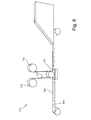
- the strip 111 is perforated by means of the apparatus 110 for obtaining a random code useable in a device 10 for unique identification of a product according to the invention, it is subsequently cut at a suitable cutting station not illustrated, in such a manner to form a first layer 11 bearing a code 14 formed by the entirety of created holes.
- such code 14 has a distribution of the holes and a configuration of the same that the known apparatus are capable of reproducing only approximately through a sampling of the original thus obtaining a copy which is always distinguishable from the original.
- Such first layer 11 is subsequently coupled to a second layer 12 capable of providing an action of optical contrast.
- the first layer 11 is also covered through a third layer 13 for protecting and selecting a portion of the code 14 present on such first layer 11.
- the second layer 12 suitable to provide an action of optical contrast, increases the accuracy of detecting the code 14 when memorizing or verifying the same.
- the second layer 12 is arranged at the lower part with respect to the first layer 11, in such a manner that the surface of the second layer 12 is visible through the holes forming the code 14 present on the first layer 11.
- the optical contrast may be obtained through two different types, diversified according to the optical perceptibility of the human eye: the chromatic contrast or achromatic contrast.
- chromatic contrasts sensitive to human eye.
- the human eye perceives a coloured body when the surface thereof reflects the light incident with waves characterized by a wavelength comprised between about 400nm and 800nm. Therefore, exploited in case of chromatic contrast is the contrast between two different colours, i.e. by two different wavelengths reflected by the surfaces of the first 11 and second 12 layer when subjected to light having wavelengths comprised between 400nm and 800nm.
- the source of light may be natural light, while the detector is the human eye.
- chromatic contrast As extreme cases, are contrasts generated by black on white or by white on black as illustrated in figures 8a and 8b .
- achromatic contrast instead, are two surfaces chromatically identical or similar to the visible light, which, irradiated from non-visible light, either emit visible radiations having different colour, for example in case of use of fluorescent colouring agents radiated by ultraviolet light, or radiations not belonging to the visible spectrum but perceptible by a suitable detector.
- the contrast layer 12 may be obtained directly by the product to be marked.
- the second lower layer 12 has the additional task of ensuring adhesion between the identification device 10 and the product it should mark, and simultaneously ensure the durability of the code provided for during the design step.
- the second layer 12 is made up of material capable of guaranteeing perfect adhesion between the device 10 and the product, in such a manner to ensure firm connection even under environmental conditions (temperature and humidity) beyond standard values with a preset safety margin, and having chemical/physical characteristics capable of resisting against the combined action of temperature, humidity and abrasion.
- Teflon polytetrafluoroethylene
- polyethylene polyethylene
- the first layer 11 having the code 14 is also made of polymer material capable of offering capacity of perfect adhesion to the product to be marked or to the second layer 12 and a possible third layer 13 arranged at the upper part with respect to the same, and resistance, within a given safety margin, under harsh hygrothermal and mechanical conditions. Such characteristics are always observed in the same polymers mentioned previously.
- the first layer 11 is advantageously made of polyester, given that such material is particularly resistant in case of washing, for example if the device 10 for unique identification of a product is used in the clothes industry.
- the device 10 for unique identification of a product also comprises a third layer 13 arranged at the upper part with respect to the first layer 11 for protecting and selecting a portion of the code 14 present on such first layer 11.
- the third layer 13 at the upper part has a first portion 13a permeable to light, for example made of transparent or semitransparent material or also by removal of material, through which it is possible to detect the code present on the first layer 11, and a second portion 13b made of material non-permeable to light, preferably frame-like, arranged around the first portion 13a permeable to light.
- the third layer 13 thus defines the margins for reading the code 14, defining a clear contour between the readable portion of the code 14, in that arranged at the first portion 13a permeable to light, and the portion non-permeable to light 13b.
- Such third layer 13 for protecting and selecting the code offers the advantage of having the code with a geometric shape and a surface layer definitely matching that of the type of the sold product.
- a digital image detector such as for example a video camera or digital camera, having a resolution sufficient to guarantee the required acquisition precision.
- the required resolution depends on the size of the holes with which the code is created. For example if the code is made up of 1mm holes, a 640x480 pixels resolution is sufficient, i.e. the resolution generally available in cameras cellular phone devices are provided with. Otherwise, if the holes have dimensions equivalent to 0.5 mm, the minimum resolution must be at least equivalent to 1280x1024 pixels.
- the model of the code 14 is memorised in local memory means, for example contained in a palmtop, or centralised, access to which is possible through wireless connections or through the internet, depending on the particular application requirements.
- the transmission of the image acquired using a cellular phone may for example occur by sending an MMS (Multimedia Messaging Service).
- MMS Multimedia Messaging Service
- any data transmission means may be suitable for sending such image.
- the transmitted image is processed through the same processing means with the aim of identifying a digital model bearing the positioning and shape of the holes present in the detected code.
- the code 14 is thus identified as a counterfeit product.
- the reliability of a device for unique identification of a product is given by the irreproducibility of the code borne by the same.
- the apparatus and the method for obtaining a random code useable in a device for unique identification of a product according to the present invention are capable of generating a code made up of a plurality of holes which are distributed and shaped in such a manner that the apparatus used nowadays for obtaining and cloning codes are capable of solely approximately reproducing through a sampling of the original, thus obtaining a copy always distinguishable from the original.
Landscapes
- Engineering & Computer Science (AREA)
- Physics & Mathematics (AREA)
- General Physics & Mathematics (AREA)
- Theoretical Computer Science (AREA)
- Business, Economics & Management (AREA)
- Accounting & Taxation (AREA)
- Finance (AREA)
- Manufacturing & Machinery (AREA)
- Credit Cards Or The Like (AREA)
- Manufacture, Treatment Of Glass Fibers (AREA)
- Vending Machines For Individual Products (AREA)
Applications Claiming Priority (1)
| Application Number | Priority Date | Filing Date | Title |
|---|---|---|---|
| ITMI2009A000324A IT1393124B1 (it) | 2009-03-05 | 2009-03-05 | Dispositivo di identificazione univoca di un prodotto nonche' metodo ed apparecchiatura di realizzazione di detto dispositivo |
Publications (1)
| Publication Number | Publication Date |
|---|---|
| EP2226745A1 true EP2226745A1 (de) | 2010-09-08 |
Family
ID=41478925
Family Applications (1)
| Application Number | Title | Priority Date | Filing Date |
|---|---|---|---|
| EP10155485A Withdrawn EP2226745A1 (de) | 2009-03-05 | 2010-03-04 | Vorrichtung und Verfahren zum Erhalten eines zufälligen Codes, der in einer Vorrichtung zur einzigartigen Identifizierung eines Produkts benutzt werden kann |
Country Status (4)
| Country | Link |
|---|---|
| US (1) | US8070063B2 (de) |
| EP (1) | EP2226745A1 (de) |
| CA (1) | CA2695316A1 (de) |
| IT (1) | IT1393124B1 (de) |
Cited By (2)
| Publication number | Priority date | Publication date | Assignee | Title |
|---|---|---|---|---|
| WO2012038842A1 (en) * | 2010-09-22 | 2012-03-29 | International Business Machines Corporation | Product embodying a physical unclonable function |
| WO2021133305A1 (en) * | 2019-12-26 | 2021-07-01 | T.C. Erciyes Universitesi | Fabrication of physically unclonable security labels based on polymer thin films |
Citations (3)
| Publication number | Priority date | Publication date | Assignee | Title |
|---|---|---|---|---|
| EP0193334A2 (de) | 1985-02-18 | 1986-09-03 | Dai Nippon Insatsu Kabushiki Kaisha | Optische Karten und Verfahren zu ihrer Herstellung |
| GB2369078A (en) | 2000-11-16 | 2002-05-22 | Smartwater Ltd | Microparticle production by laser cutting |
| US20050006481A1 (en) | 1998-11-12 | 2005-01-13 | Wenyu Han | Card with enhanced security features |
Family Cites Families (4)
| Publication number | Priority date | Publication date | Assignee | Title |
|---|---|---|---|---|
| JP3784875B2 (ja) * | 1996-02-13 | 2006-06-14 | 株式会社湯山製作所 | 識別方法及びその装置 |
| US6176434B1 (en) * | 1998-04-17 | 2001-01-23 | Forensic Technology Wai Inc. | Method and structure for identifying solid objects having a dynamic surface |
| US6193156B1 (en) * | 1998-11-12 | 2001-02-27 | Wenyu Han | Method and apparatus for patterning cards, instruments and documents |
| GB0031016D0 (en) * | 2000-12-20 | 2001-01-31 | Alphafox Systems Ltd | Security systems |
-
2009
- 2009-03-05 IT ITMI2009A000324A patent/IT1393124B1/it active
-
2010
- 2010-03-03 CA CA2695316A patent/CA2695316A1/en not_active Abandoned
- 2010-03-04 EP EP10155485A patent/EP2226745A1/de not_active Withdrawn
- 2010-03-04 US US12/717,508 patent/US8070063B2/en not_active Expired - Fee Related
Patent Citations (3)
| Publication number | Priority date | Publication date | Assignee | Title |
|---|---|---|---|---|
| EP0193334A2 (de) | 1985-02-18 | 1986-09-03 | Dai Nippon Insatsu Kabushiki Kaisha | Optische Karten und Verfahren zu ihrer Herstellung |
| US20050006481A1 (en) | 1998-11-12 | 2005-01-13 | Wenyu Han | Card with enhanced security features |
| GB2369078A (en) | 2000-11-16 | 2002-05-22 | Smartwater Ltd | Microparticle production by laser cutting |
Cited By (5)
| Publication number | Priority date | Publication date | Assignee | Title |
|---|---|---|---|---|
| WO2012038842A1 (en) * | 2010-09-22 | 2012-03-29 | International Business Machines Corporation | Product embodying a physical unclonable function |
| GB2497032A (en) * | 2010-09-22 | 2013-05-29 | Ibm | Product embodying a physical unclonable function |
| GB2497032B (en) * | 2010-09-22 | 2013-12-25 | Ibm | Product embodying a physical unclonable function |
| DE112011103162B4 (de) * | 2010-09-22 | 2016-09-01 | International Business Machines Corporation | Produkt, das eine physische, nicht klonbare Funktion verkörpert |
| WO2021133305A1 (en) * | 2019-12-26 | 2021-07-01 | T.C. Erciyes Universitesi | Fabrication of physically unclonable security labels based on polymer thin films |
Also Published As
| Publication number | Publication date |
|---|---|
| ITMI20090324A1 (it) | 2010-09-06 |
| IT1393124B1 (it) | 2012-04-11 |
| US8070063B2 (en) | 2011-12-06 |
| US20100224686A1 (en) | 2010-09-09 |
| CA2695316A1 (en) | 2010-09-05 |
Similar Documents
| Publication | Publication Date | Title |
|---|---|---|
| CN102099844B (zh) | 通过光学设备要被存储的意义单一的标签、生产该标签的方法及其在产品防伪和产品识别中的应用 | |
| US20210352192A1 (en) | Recycling methods and systems, and related plastic containers | |
| CN106682912B (zh) | 3d结构的认证方法 | |
| JP2009262559A (ja) | 平らな基体に偽造防止マークを製造する方法 | |
| US20250229461A1 (en) | Recycling methods and systems, and related plastic containers | |
| CN109311051A (zh) | 用于生产效应层的方法 | |
| CN107111302A (zh) | 鉴别用于增材制造的材料的特性 | |
| CN110154190A (zh) | 一种具有在线视觉检测功能的家居板件生产线及检测方法 | |
| JP2011511322A (ja) | セキュリティエレメント | |
| US20190344506A1 (en) | Three-Dimensional Printing Method for Producing a Product Protected Against Forgery by Means of a Security Feature | |
| US8070063B2 (en) | Apparatus and method for obtaining a random code useable in a device for unique identification of a product | |
| CN101364359A (zh) | 一种防伪标识物 | |
| CN109116463A (zh) | 用于印刷到光学波导上的图像的图像特定照明的系统和方法 | |
| EP3863784A1 (de) | Etikettendesign für generatives fertigungsverfahren | |
| US20180050501A1 (en) | Apparatus and Method to Authenticate 3D Printer Consumables | |
| JP2002067032A (ja) | 表示装置およびプラスチック識別装置 | |
| US11119263B2 (en) | System and method for image specific illumination of image printed on optical waveguide | |
| CN107870520A (zh) | 图案制造装置、图案制造方法及图案制造程序 | |
| CN107870506A (zh) | 图案形成片、图案制造装置、图案制造方法及图案制造程序 | |
| CN110781697A (zh) | 视觉验证系统和方法 | |
| CN102881222B (zh) | 微型码防伪标签制作方法 | |
| CN103455833A (zh) | 一种三维码生成的方法及设备 | |
| CN109118991A (zh) | 用于印刷到光学波导上的图像的图像特定照明的系统和方法 | |
| CN112074832A (zh) | 用于制造安全装置的方法 | |
| CN105590122B (zh) | 一种具有不同印制高度的防伪二维码的印制方法及装置 |
Legal Events
| Date | Code | Title | Description |
|---|---|---|---|
| PUAI | Public reference made under article 153(3) epc to a published international application that has entered the european phase |
Free format text: ORIGINAL CODE: 0009012 |
|
| AK | Designated contracting states |
Kind code of ref document: A1 Designated state(s): AT BE BG CH CY CZ DE DK EE ES FI FR GB GR HR HU IE IS IT LI LT LU LV MC MK MT NL NO PL PT RO SE SI SK SM TR |
|
| 17P | Request for examination filed |
Effective date: 20110307 |
|
| STAA | Information on the status of an ep patent application or granted ep patent |
Free format text: STATUS: THE APPLICATION IS DEEMED TO BE WITHDRAWN |
|
| 18D | Application deemed to be withdrawn |
Effective date: 20161001 |