EP2226868A1 - Wiederaufladbare Batterie und Modul dafür - Google Patents
Wiederaufladbare Batterie und Modul dafür Download PDFInfo
- Publication number
- EP2226868A1 EP2226868A1 EP10155469A EP10155469A EP2226868A1 EP 2226868 A1 EP2226868 A1 EP 2226868A1 EP 10155469 A EP10155469 A EP 10155469A EP 10155469 A EP10155469 A EP 10155469A EP 2226868 A1 EP2226868 A1 EP 2226868A1
- Authority
- EP
- European Patent Office
- Prior art keywords
- case
- short
- unit
- circuit
- electrode terminal
- Prior art date
- Legal status (The legal status is an assumption and is not a legal conclusion. Google has not performed a legal analysis and makes no representation as to the accuracy of the status listed.)
- Granted
Links
Images


Classifications
-
- H—ELECTRICITY
- H01—ELECTRIC ELEMENTS
- H01M—PROCESSES OR MEANS, e.g. BATTERIES, FOR THE DIRECT CONVERSION OF CHEMICAL ENERGY INTO ELECTRICAL ENERGY
- H01M50/00—Constructional details or processes of manufacture of the non-active parts of electrochemical cells other than fuel cells, e.g. hybrid cells
- H01M50/50—Current conducting connections for cells or batteries
- H01M50/572—Means for preventing undesired use or discharge
-
- H—ELECTRICITY
- H01—ELECTRIC ELEMENTS
- H01M—PROCESSES OR MEANS, e.g. BATTERIES, FOR THE DIRECT CONVERSION OF CHEMICAL ENERGY INTO ELECTRICAL ENERGY
- H01M50/00—Constructional details or processes of manufacture of the non-active parts of electrochemical cells other than fuel cells, e.g. hybrid cells
- H01M50/50—Current conducting connections for cells or batteries
- H01M50/572—Means for preventing undesired use or discharge
- H01M50/574—Devices or arrangements for the interruption of current
-
- H—ELECTRICITY
- H01—ELECTRIC ELEMENTS
- H01M—PROCESSES OR MEANS, e.g. BATTERIES, FOR THE DIRECT CONVERSION OF CHEMICAL ENERGY INTO ELECTRICAL ENERGY
- H01M50/00—Constructional details or processes of manufacture of the non-active parts of electrochemical cells other than fuel cells, e.g. hybrid cells
- H01M50/10—Primary casings; Jackets or wrappings
-
- H—ELECTRICITY
- H01—ELECTRIC ELEMENTS
- H01M—PROCESSES OR MEANS, e.g. BATTERIES, FOR THE DIRECT CONVERSION OF CHEMICAL ENERGY INTO ELECTRICAL ENERGY
- H01M50/00—Constructional details or processes of manufacture of the non-active parts of electrochemical cells other than fuel cells, e.g. hybrid cells
- H01M50/10—Primary casings; Jackets or wrappings
- H01M50/102—Primary casings; Jackets or wrappings characterised by their shape or physical structure
- H01M50/103—Primary casings; Jackets or wrappings characterised by their shape or physical structure prismatic or rectangular
-
- H—ELECTRICITY
- H01—ELECTRIC ELEMENTS
- H01M—PROCESSES OR MEANS, e.g. BATTERIES, FOR THE DIRECT CONVERSION OF CHEMICAL ENERGY INTO ELECTRICAL ENERGY
- H01M50/00—Constructional details or processes of manufacture of the non-active parts of electrochemical cells other than fuel cells, e.g. hybrid cells
- H01M50/10—Primary casings; Jackets or wrappings
- H01M50/116—Primary casings; Jackets or wrappings characterised by the material
- H01M50/117—Inorganic material
- H01M50/119—Metals
-
- H—ELECTRICITY
- H01—ELECTRIC ELEMENTS
- H01M—PROCESSES OR MEANS, e.g. BATTERIES, FOR THE DIRECT CONVERSION OF CHEMICAL ENERGY INTO ELECTRICAL ENERGY
- H01M50/00—Constructional details or processes of manufacture of the non-active parts of electrochemical cells other than fuel cells, e.g. hybrid cells
- H01M50/10—Primary casings; Jackets or wrappings
- H01M50/172—Arrangements of electric connectors penetrating the casing
- H01M50/174—Arrangements of electric connectors penetrating the casing adapted for the shape of the cells
- H01M50/176—Arrangements of electric connectors penetrating the casing adapted for the shape of the cells for prismatic or rectangular cells
-
- H—ELECTRICITY
- H01—ELECTRIC ELEMENTS
- H01M—PROCESSES OR MEANS, e.g. BATTERIES, FOR THE DIRECT CONVERSION OF CHEMICAL ENERGY INTO ELECTRICAL ENERGY
- H01M50/00—Constructional details or processes of manufacture of the non-active parts of electrochemical cells other than fuel cells, e.g. hybrid cells
- H01M50/50—Current conducting connections for cells or batteries
- H01M50/543—Terminals
-
- H—ELECTRICITY
- H01—ELECTRIC ELEMENTS
- H01M—PROCESSES OR MEANS, e.g. BATTERIES, FOR THE DIRECT CONVERSION OF CHEMICAL ENERGY INTO ELECTRICAL ENERGY
- H01M50/00—Constructional details or processes of manufacture of the non-active parts of electrochemical cells other than fuel cells, e.g. hybrid cells
- H01M50/50—Current conducting connections for cells or batteries
- H01M50/543—Terminals
- H01M50/547—Terminals characterised by the disposition of the terminals on the cells
- H01M50/55—Terminals characterised by the disposition of the terminals on the cells on the same side of the cell
-
- H—ELECTRICITY
- H01—ELECTRIC ELEMENTS
- H01M—PROCESSES OR MEANS, e.g. BATTERIES, FOR THE DIRECT CONVERSION OF CHEMICAL ENERGY INTO ELECTRICAL ENERGY
- H01M50/00—Constructional details or processes of manufacture of the non-active parts of electrochemical cells other than fuel cells, e.g. hybrid cells
- H01M50/50—Current conducting connections for cells or batteries
- H01M50/543—Terminals
- H01M50/552—Terminals characterised by their shape
- H01M50/553—Terminals adapted for prismatic, pouch or rectangular cells
-
- H—ELECTRICITY
- H01—ELECTRIC ELEMENTS
- H01M—PROCESSES OR MEANS, e.g. BATTERIES, FOR THE DIRECT CONVERSION OF CHEMICAL ENERGY INTO ELECTRICAL ENERGY
- H01M2200/00—Safety devices for primary or secondary batteries
- H01M2200/20—Pressure-sensitive devices
-
- Y—GENERAL TAGGING OF NEW TECHNOLOGICAL DEVELOPMENTS; GENERAL TAGGING OF CROSS-SECTIONAL TECHNOLOGIES SPANNING OVER SEVERAL SECTIONS OF THE IPC; TECHNICAL SUBJECTS COVERED BY FORMER USPC CROSS-REFERENCE ART COLLECTIONS [XRACs] AND DIGESTS
- Y02—TECHNOLOGIES OR APPLICATIONS FOR MITIGATION OR ADAPTATION AGAINST CLIMATE CHANGE
- Y02E—REDUCTION OF GREENHOUSE GAS [GHG] EMISSIONS, RELATED TO ENERGY GENERATION, TRANSMISSION OR DISTRIBUTION
- Y02E60/00—Enabling technologies; Technologies with a potential or indirect contribution to GHG emissions mitigation
- Y02E60/10—Energy storage using batteries
Definitions
- Embodiments of the present invention relate to a rechargeable battery and a module thereof, and more particularly, to a rechargeable battery and a module thereof that can prevent or reduce overcharge.
- a large-capacity rechargeable battery may be used as a power supply for driving a motor of an electric vehicle or a hybrid electric vehicle (HEV).
- a large-capacity rechargeable battery is typically provided with a plurality of rechargeable batteries consisting of unit cells and is formed by connecting the unit cells to each other in series.
- a large-capacity rechargeable battery may have a circular or a prismatic shape.
- the prismatic shape generally provides a better heat radiating performance than the circular shape. Therefore, the prismatic shape is more advantageous than the circular shape with respect to the aspect of safety against overcharge.
- circular rechargeable batteries are typically provided with a current interrupt device (CID) for interrupting current in overcharge, while prismatic rechargeable batteries are typically not provided with a CID.
- CID current interrupt device
- the size of the rechargeable battery may increase.
- a difference in heat radiation may be caused inside and outside of the unit cell due to an increase of a thickness thereof, such that safe charging may be difficult to provide.
- Embodiments of the present invention provide a unit cell, a rechargeable battery and a module thereof for preventing or reducing overcharge.
- Embodiments of the present invention provide a unit cell, a rechargeable battery and a module thereof for providing stability from overcharge in a prismatic rechargeable battery having increased thickness.
- the present invention is directed to a unit cell comprising a case containing an electrode assembly; a cap plate coupled to the case and sealing an opening of the case; a first electrode terminal connected to a first electrode of the electrode assembly and electrically connected to the case; a second electrode terminal connected to a second electrode of the electrode assembly and electrically insulated from the case when a pressure inside the case is less than a threshold pressure; and a short-circuit unit comprising a short-circuit member connected to the second electrode terminal, the short-circuit unit adapted to short-circuit the second electrode terminal to the case by swelling a portion of the case to contact the short-circuit member when the pressure inside the case is equal to or greater than the threshold pressure.
- the case of the unit cell of the invention can have a prismatic hexahedron shape, and the short-circuit unit can be on a surface of the case.
- the case can comprise a first surface and a second surface facing each other and each having a substantially same first area; a third surface and a fourth surface facing each other and being between the first and second surfaces, each of the third and fourth surfaces having a substantially same second area smaller than the first area; and a fifth surface facing the opening and having a width substantially equal to a width of the third and fourth surfaces.
- the first surface or the second surface extends in a first direction and includes cell barriers spaced from each other in a second direction that crosses the first direction, the cell barriers defining at least one flow passage therebetween for passage of a heat transfer medium therethrough.
- the short-circuit unit of the unit cell of the invention can be located on the third surface or the fourth surface of the can.
- the unit cell of the ivention can further comprise an insulating layer on outer surfaces of the case other than the surface having the short-circuit unit thereon.
- the unit cell of the invention can further comprise an insulating layer on outer surfaces of the cell barriers.
- the short-circuit unit can further comprise a swelling induction unit comprising the portion of the case, the portion of the case having a thickness (T2) that is less than a thickness (T1) of another portion of the case surrounding the portion, and wherein the short-circuit member faces and is contactable with an outer surface of the portion of the case.
- the swelling induction unit is concave on an inner surface of the portion of the case, and the short-circuit member comprises a mounting portion mounted to the second electrode terminal and a short-circuit end facing and contactable with the swelling induction unit.
- the short-circuit member can be bent between the mounting portion and the short-circuit end, the mounting portion being substantially horizontal, and the short-circuit end being substantially vertical.
- the short-circuit unit may further comprise a bracket connected to the case and supporting the short-circuit end, and an insulating member between the short-circuit end and the bracket.
- the unit cell of the invention further comprises an outer insulator on at least an outer surface of the cap plate; and an inner insulator on an inner surface of the cap plate, wherein the outer and inner insulators receive one of the first and second electrode terminals therethrough and electrically insulate the one of the first and second electrode terminals from the cap plate.
- a rechargeable battery includes a case containing an electrode assembly; a cap plate coupled to the case and sealing an opening of the case; a first electrode terminal connected to a first electrode of the electrode assembly and electrically connected to the case; a second electrode terminal connected to a second electrode of the electrode assembly and electrically insulated from the case when a pressure inside the case is less than a threshold pressure; and a short-circuit unit including a short-circuit member connected to the second electrode terminal, the short-circuit unit adapted to short-circuit the second electrode terminal to the case by swelling a portion of the case to contact the short-circuit member when the pressure inside the case is equal to or greater than the threshold pressure.
- the case may have a prismatic hexahedron shape and the short-circuit unit may be on a surface of the case.
- the case may include a first surface and a second surface facing each other and each having a substantially same first area; a third surface and a fourth surface facing each other and being between the first and second surfaces, each of the third and fourth surfaces having a substantially same second area smaller than the first area; and a fifth surface facing the opening and having a width substantially equal to a width of the third and fourth surfaces.
- the short-circuit unit may be on the third surface or the fourth surface.
- the rechargeable battery may further include an insulating layer on outer surfaces of the case other than the surface having the short-circuit unit thereon.
- the first surface or the second surface may extend in a first direction and include cell barriers spaced from each other in a second direction that crosses the first direction, the cell barriers defining at least one flow passage therebetween for passage of a heat transfer medium therethrough.
- the rechargeable battery may further include an insulating layer on outer surfaces of the cell barriers.
- the short-circuit unit may include a swelling induction unit including the portion of the case, the portion of the case having a thickness that is less than a thickness of another portion of the case surrounding the portion, and the short-circuit member may face and be contactable with an outer surface of the portion of the case.
- the swelling induction unit may be concave on an inner surface of the portion of the case, and the short-circuit member may include a mounting portion mounted to the second electrode terminal, and a short-circuit end facing and contactable with the swelling induction unit.
- the short-circuit member may be bent between the mounting portion and the short-circuit end, the mounting portion being substantially horizontal, and the short-circuit end being substantially vertical.
- the short-circuit unit may further include a bracket connected to the case and supporting the short-circuit end, and an insulating member between the short-circuit end and the bracket.
- the first electrode terminal may be a positive electrode terminal, and the second electrode terminal may be a negative electrode terminal.
- the rechargeable battery may include an outer insulator on at least an outer surface of the cap plate, and an inner insulator on an inner surface of the cap plate, and the outer and inner insulators may receive one of the first and second electrode terminals therethrough and electrically insulate the one of the first and second electrode terminals from the cap plate.
- a rechargeable battery module includes a plurality of unit cells adjacent one another, and at least one bus bar connecting unit cells of the plurality of unit cells to each other in series, wherein a unit cell of the plurality of unit cells includes a case containing an electrode assembly; a cap plate coupled to the case and sealing an opening of the case; a first electrode terminal connected to a first electrode of the electrode assembly and electrically connected to the case; a second electrode terminal connected to a second electrode of the electrode assembly and electrically insulated from the case when a pressure inside the case is less than a threshold pressure; and a short-circuit unit including a short-circuit member connected to the second electrode terminal, the short-circuit unit adapted to short-circuit the second electrode terminal to the case by swelling a portion of the case to contact the short-circuit member when the pressure inside the case is equal to or greater than the threshold pressure.
- an insulating layer is on an outer surface of a case, one electrode terminal is electrically connected to the case, and a short-circuit unit is adapted to short-circuit another electrode terminal and the case by swelling the case, thereby preventing or reducing overcharging. That is, since charged current is discharged by the short-circuit while charging is continuous without current interruption, an increase of voltage and temperature can be prevented or reduced.
- the present invention also refers to A rechargeable battery module comprising a plurality of unit cells adjacent one another; and at least one bus bar connecting unit cells of the plurality of unit cells to each other in series, wherein a unit cell of the plurality of unit cells comprises a case containing an electrode assembly; a cap plate coupled to the case and sealing an opening of the case; a first electrode terminal connected to a first electrode of the electrode assembly and electrically connected to the case; a second electrode terminal connected to a second electrode of the electrode assembly and electrically insulated from the case when a pressure inside the case is less than a threshold pressure; and a short-circuit unit comprising a short-circuit member connected to the second electrode terminal, the short-circuit unit adapted to short-circuit the second electrode terminal to the case by swelling a portion of the case to contact the short-circuit member when the pressure inside the case is equal to or greater than the threshold pressure.
- the short-circuit unit may comprise a swelling induction unit comprising a portion of the case, the portion of the case having a thickness that is less than a thickness of another portion of the case surrounding the portion, and wherein the short-circuit member faces and is contactable with an outer surface of the portion of the case.
- the swelling induction unit can be concave on an inner surface of the portion of the case
- the short-circuit member can comprise a mounting portion mounted to the second electrode terminal, and a short-circuit end facing and contactable with the swelling induction unit.
- the short-circuit member can be bent between the mounting portion and the short-circuit end, the mounting portion being substantially horizontal, and the short-circuit end being substantially vertical.
- the short-circuit unit can further comprise a bracket connected to the case and supporting the short-circuit end, and an insulating member between the short-circuit end and the bracket.
- the unit cell of the plurality of unit cells can further comprise an insulating layer on an outer surface of the case.
- the first electrode terminal of the unit cell of the rechargeable battery module is a positive electrode terminal
- the second electrode terminal of the unit cell is a negative electrode terminal.
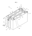
- FIG. 1 is a perspective view of a rechargeable battery module according to an exemplary embodiment of the present invention.
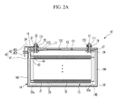
- FIG. 2A is a cross-sectional view of a unit cell of the rechargeable battery module of FIG. 1 taken along line II-II before operation of a short circuit unit of the rechargeable battery module.
- FIG. 2B is a cross-sectional view of a unit cell of the rechargeable battery module of FIG. 1 taken along line II-II after operation of a short circuit unit of the rechargeable battery module.
- FIG. 3 is a plan view of the rechargeable battery module of FIG. 1 .
- FIG. 4A is a cross-sectional view of a short-circuit unit of the rechargeable battery module of FIG. 1 before operation.
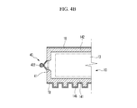
- FIG. 4B is a cross-sectional view of a short-circuit unit of the rechargeable battery module of FIG. 1 after operation.
- Unit cell 100 Rechargeable battery module 11, 12 : Positive and negative electrode terminals 111,121:Nuts 13 : Electrode assembly 14 : Case 141, 142, 143, 144, 145 : First to fifth surfaces of case 146 : Cell barrier 147 : Flow passage 15 : Cap plate 151 : Sealing closure 152 : Vent portion 153 : Terminal hole of cap plate 16, 17 : Outer and inner insulators 18 : Insulating layer 19 : Connecting member 20 : Bus bar 21 : Terminal hole of bus bar 31, 32 : Positive and negative electrodes 31 a, 32a : Uncoated region 33 : Separator 34 : Current collecting member 40 : Short-circuit unit 41 : Swelling induction unit 42 : Short-circuit member 421 : Mounting portion 422
- FIG. 1 is a perspective view of a rechargeable battery module according to an exemplary embodiment of the present invention.
- a rechargeable battery module 100 according to one exemplary embodiment includes two or more unit cells 10 that are sequentially disposed adjacent to each other and one or more bus bars 20 connecting the unit cells 10 to each other in series.
- the bus bar 20 connects a positive electrode terminal 11 of one of the unit cells 10 with a negative electrode terminal 12 of another adjacent one of the unit cells 10 in series to form the high-output rechargeable battery module 100.
- An output of the rechargeable battery module 100 is dependent on the number of unit cells 10 that are connected to each other in series.
- FIG. 2A is a cross-sectional view of one of the unit cells 10 of the rechargeable battery module 100 taken along line II-II of FIG. 1 before operation of a short circuit unit of the rechargeable battery module
- FIG. 2B is a cross-sectional view of one of the unit cells 10 of the rechargeable battery module 100 taken along line II-II of FIG. 1 after operation of a short circuit unit of the rechargeable battery module
- FIG. 3 is a plan view of the rechargeable battery module 100. Referring to FIGS. 2A , 2B and 3 , the unit cells 10 form the rechargeable battery module 100 that includes the positive electrode terminal 11 and the negative electrode terminal 12.
- each of the unit cells 10 includes an electrode assembly 13 that is connected to the positive electrode terminal 11 and the negative electrode terminal 12, a case 14 that contains the electrode assembly 13 and is electrically connected to the positive electrode terminal 11 via a connecting member 19 (shown in FIG. 2A ), a cap plate 15 that covers an opening formed at one side of the case 14, an outer insulator 16 that is installed on an outer surface of the cap plate 15, and one or more inner insulators 17 that are installed on an inner surface of the cap plate 15.
- the unit cell 10 in one embodiment, further includes an insulating layer 18 that is formed on an outer surface of the case 14.
- the insulating layer 18 may be formed by an insulating sheet that is attached with an insulating material or by an insulation coated layer that is coated with an insulating material.
- the unit cell 10 further includes a short-circuit unit 40 configured to short-circuit the negative electrode terminal 12 to the case 14 by swelling of the case 14, in which a portion of the case 14 swells in an overcharge condition.
- the electrode assembly 13 may be formed in a jelly roll shape by disposing a positive electrode 31 and a negative electrode 32 on both surfaces of a separator 33, respectively, and winding the positive electrode 31, the negative electrode 32, and the separator 33 all together.
- Each of the positive electrode 31 and the negative electrode 32 may include a coated region where a current collector formed of a thin metal foil is coated with an active material and an uncoated region 31 a and 32a where the current collector is not coated with the active material.
- the uncoated regions 31 a and 32a are formed at side ends of the positive electrode 31 and the negative electrode 32, respectively, in longitudinal directions of the positive electrode 31 and the negative electrode 32 and at side ends opposite to each other.
- the uncoated regions 31 a and 32a are connected to the positive electrode terminal 11 and the negative electrode terminal 12, respectively, through respective current collecting members 34.
- the case 14 forms an entire exterior of the unit cell 10 and is made of a conductive metal such as aluminum, an aluminum alloy, or nickel-plated steel.
- the case 14 forms a space incorporating the electrode assembly 13.
- the case 14 may have a prismatic hexahedron shape.
- the case 14 includes a pair of first and second surfaces 141 and 142 (see FIG. 3 ), each having a substantially same area (e.g., an area formed by a length and a height of the case 14) and facing each other; a pair of third and fourth surfaces 143 and 144 each having a substantially same area (e.g., an area formed by a width and the height of the case 14) smaller than the area of the first and second surfaces 141 and 142 and facing each other at two sides between the first and second surfaces 141 and 142; and a fifth surface 145 at another side between the first and second surfaces 141 and 142 and having an area (e.g., an area formed by the length and the width of the case 14) smaller than the area of the first and second surfaces 141 and 142.
- the fifth surface 145 forms a side of the case 14 opposite to an opening of the case 14.
- the cap plate 15 may be formed of a thin plate and is joined to the opening formed at one side of the case 14 and seals the opening.
- the cap plate 15 may have an electrolyte injection opening (not shown) for injecting an electrolyte into the inside of the sealed case 14.
- the electrolyte injection opening is sealed with a sealing closure 151 after injecting the electrolyte.
- the cap plate 15 may have a vent portion 152 cut depending on an internal pressure set to prevent explosion of the unit cell 10.
- the cap plate 15 has a pair of terminal holes 153 that each receive one of the positive electrode terminal 11 and the negative electrode terminal 12 therethrough.
- the positive electrode terminal 11 and the negative electrode terminal 12 are joined to the terminal holes 153 of the cap plate 15 to be connected to a respective current collecting member 34 in the case 14 and be connected to the electrode assembly 13 through the current collecting member 34.
- the outer insulator 16 is partially inserted into the terminal hole 153 of the negative electrode terminal 12 outside of the cap plate 15 to electrically insulate the negative electrode terminal 12 from the cap plate 15. That is, the outer insulator 16 insulates the negative electrode terminal 12 from the outer surface of the cap plate 15 and, at the same time, insulates the negative electrode terminal 12 from an inner surface of the terminal hole 153 of the cap plate 15 of the negative electrode terminal 12.
- a part corresponding to the outer surface of the cap plate 15 and a part corresponding to the inner surface of the terminal hole 153 are integrally formed, but may alternatively be formed separate from each other (not shown).
- the bus bar 20 is provided with a pair of terminal holes 21 that correspond to the positive electrode terminal 11 and the negative electrode terminal 12 of the adjacent unit cells 10.
- the bus bar 20 is installed on the outer insulator 16 of each of the adjacent unit cells 10 by inserting the positive electrode terminal 11 and the negative electrode terminal 12 through the terminal holes 21.
- Nuts 111 and 121 are joined to the positive electrode terminal 11 and the negative electrode terminal 12, respectively, such that the bus bar 20 connects the positive electrode terminal 11 and the negative electrode terminal 12 to each other in series in a pair of unit cells 10.
- the outer insulator 16 supports the bus bar 20 and is between the cap plate 15 and the bus bar 20 (see FIG. 2A ).
- the inner insulators 17 are provided to correspond to the terminal holes 153 inside of the cap plate 15 and electrically insulate the current collecting members 34 from the cap plate 15 on the inner surface of the cap plate 15.
- each of a pair of current collecting members 34 connects the positive electrode 31 and the negative electrode 32 of the electrode assembly 13 to the positive electrode terminal 11 and the negative electrode terminal 12, respectively.
- the positive electrode terminal 11 is electrically connected to the case 14 through the connecting member 19, but the negative electrode terminal 12 and the case 14 are insulated from each other for normal operation of the unit cell 10.
- the connecting member 19 may be made of conductive material such as copper or aluminum.
- the negative electrode terminal 12 may be electrically connected to the case 14 and the positive electrode terminal 11 and the case 14 may be insulated from each other (not shown).
- the short-circuit unit 40 may short-circuit the positive electrode terminal 11 and the case 14 to each other.
- the short-circuit unit 40 When the unit cell 10 is overcharged (see FIGs. 2B and 4B ) and deviating from a normal operating range (see FIGs. 2A and 4A ), the short-circuit unit 40 short-circuits the negative electrode terminal 12 to the case 14. As a result, while current charging is continuous, the short-circuit unit 40 discharges current by electrically connecting the case 14 and the negative electrode terminal 12, thereby preventing additional increases of voltage and temperature of the unit cell 10. As a result, safety of the unit cell 10 from overcharge is secured.
- the outer insulator 16 and the inner insulator 17 insulate the negative electrode terminal 12 and the case 14 from each other, and the short-circuit unit 40 selectively short-circuits the negative electrode terminal 12 and the case 14 to each other in an overcharge condition.
- the outer insulator 16 and the inner insulator 17 and the short-circuit unit 40 perform opposite functions.
- the short-circuit unit 40 is formed on one surface of the case 14, that is, either one of the third and fourth surfaces 143 and 144, and the insulating layer 18 is formed on other surfaces of the case 14 where the short-circuit unit 40 is not formed.
- the short-circuit unit 40 is formed on the third surface 143 of the case 14 and the insulating layer 18 is formed on the first, second, fourth, and fifth surfaces 141, 142, 144, and 145.
- the insulating layer 18 may be further formed on a part of the third surface 143 except for a part corresponding to the short-circuit unit 40 (not shown).
- either one of the first and second surfaces 141 and 142 is provided with cell barriers 146 to form flow passages 147 therebetween for passage of a heat transmission medium.
- the cell barriers 146 extend in a first direction (e.g., along the z-axis direction of FIG. 3 ) and are spaced from each other at a predetermined interval in a second direction (e.g., the x-axis direction of FIG. 3 ) that crosses the z-axis direction.
- each of the flow passages 147 is formed as a space between adjacent ones of the cell barriers 146 that are formed on the first surface 141 of one unit cell 10 of two adjacent unit cells 10 and the second surface 142 of the other unit cell 10 of the two adjacent unit cells 10.
- the insulating layer 18 formed on the first surface 141 is also formed on outer surfaces of the cell barriers 146 formed on the first surface 141.
- the insulating layer 18 formed on the cell barriers 146 prevents the cases 14 that are electrically connected to the positive electrode terminal 11 in the adjacent unit cells 10 from being connected in series.
- the short-circuit unit 40 in an exemplary embodiment, includes a swelling induction unit 41 formed on the third surface 143 of the case 14 and a short-circuit member 42.
- the swelling induction unit 41 is formed on the case 14, and the short-circuit member 42 faces the swelling induction unit 41 and is connected to the negative electrode terminal 12.
- FIGS. 4A and 4B are cross-sectional views of the short-circuit unit 40 of the rechargeable battery module 100 before and after operation (e.g., due to an overcharge condition), respectively.
- the swelling induction unit 41 is formed on the third surface 143 of the case 14 and has a second thickness T2 that is thinner than a first thickness T1 of the surrounding portions of the third surface 143 (see also FIG. 2A ).
- the first to fifth surfaces 141 to 145 including the portion of the third surface 143 having the first thickness T1
- the swelling induction unit 41 of the third surface 143 may be expanded, or bulged, before the other surfaces (see FIGs. 2B and 4B ).
- the swelling induction unit 41 is concave on an inner surface of the third surface 143 and is configured to bulge outwardly in the region having the second thickness T2 due to the internal pressure.
- the short-circuit member 42 is electrically connected to the negative electrode terminal 12 at one side thereof and faces an outer surface of the swelling induction unit 41 at the other side thereof. That is, in one embodiment, the short-circuit member 42 includes a mounting portion 421 that is mounted on the negative electrode terminal 12 and a short-circuit end 422 that faces the swelling induction unit 41, and the short-circuit member 42 is bent between the mounting portion 421 and the short-circuit end 422 (e.g., bent from a horizontal orientation at the mounting portion 421 to a vertical orientation at the short-circuit end 422).
- the portion of the third surface 143 having the second thickness T2 that is, the swelling induction unit 41, and the short-circuit member 42 may be electrically short-circuited to each other. That is, when the swelling induction unit 41 and the short-circuit end 422 are short-circuited to each other, each of the negative electrode terminal 12, the mounting unit 421, the short-circuit end 422, and the swelling induction unit 41 are electrically connected to each other.
- the swelling induction unit 41 is electrically connected to the positive electrode terminal 11 on the third surface 143 of the case 14, the positive electrode terminal 11 and the negative electrode terminal 12 are short-circuited to each other. Accordingly, since charged current is discharged through the short-circuit member 42 even though charging is continuous in the unit cell 10, safety against overcharge is secured.
- the short-circuit unit 40 may include a bracket 43 and an insulating member 44.
- the bracket 43 is connected to the third surface 143 of the case 14 to stably support the short-circuit end 422, thereby preventing the short-circuit end 422 from being unnecessarily short-circuited to the swelling induction unit 41.
- the insulating member 44 is interposed between the portion of the short-circuit end 422 penetrating the bracket 43 and the bracket 43 to electrically insulate the short-circuit end 422 and the bracket 43 from each other.
Landscapes
- Chemical & Material Sciences (AREA)
- Chemical Kinetics & Catalysis (AREA)
- Electrochemistry (AREA)
- General Chemical & Material Sciences (AREA)
- Inorganic Chemistry (AREA)
- Connection Of Batteries Or Terminals (AREA)
- Sealing Battery Cases Or Jackets (AREA)
- Secondary Cells (AREA)
- Battery Mounting, Suspending (AREA)
Applications Claiming Priority (1)
| Application Number | Priority Date | Filing Date | Title |
|---|---|---|---|
| KR1020090018604A KR101041153B1 (ko) | 2009-03-04 | 2009-03-04 | 이차전지 및 그 모듈 |
Publications (2)
| Publication Number | Publication Date |
|---|---|
| EP2226868A1 true EP2226868A1 (de) | 2010-09-08 |
| EP2226868B1 EP2226868B1 (de) | 2011-10-05 |
Family
ID=42111321
Family Applications (1)
| Application Number | Title | Priority Date | Filing Date |
|---|---|---|---|
| EP10155469A Not-in-force EP2226868B1 (de) | 2009-03-04 | 2010-03-04 | Wiederaufladbare Batterie und Modul dafür |
Country Status (6)
| Country | Link |
|---|---|
| US (1) | US8557418B2 (de) |
| EP (1) | EP2226868B1 (de) |
| JP (1) | JP5256231B2 (de) |
| KR (1) | KR101041153B1 (de) |
| CN (1) | CN101826611B (de) |
| AT (1) | ATE527706T1 (de) |
Cited By (13)
| Publication number | Priority date | Publication date | Assignee | Title |
|---|---|---|---|---|
| EP2432042A1 (de) * | 2010-09-17 | 2012-03-21 | SB LiMotive Co., Ltd. | Wiederaufladbare Batterie |
| WO2013087304A1 (de) * | 2011-12-15 | 2013-06-20 | Robert Bosch Gmbh | Batteriezelle, batterie, kraftfahrzeug |
| EP2624327A1 (de) * | 2012-02-01 | 2013-08-07 | Samsung SDI Co., Ltd. | Wiederaufladbare Batterie |
| CN103493255A (zh) * | 2011-05-17 | 2014-01-01 | 株式会社Lg化学 | 改善的安全性的电池组 |
| CN103811694A (zh) * | 2012-11-07 | 2014-05-21 | 本田技研工业株式会社 | 蓄电装置及蓄电装置的车辆搭载结构 |
| DE102013200923A1 (de) * | 2013-01-22 | 2014-08-07 | Robert Bosch Gmbh | Batterieterminal mit Sicherungselement |
| DE102013201887A1 (de) * | 2013-02-06 | 2014-08-07 | Robert Bosch Gmbh | Akkumulator |
| EP2768069A1 (de) * | 2013-02-14 | 2014-08-20 | Samsung SDI Co., Ltd. | Batteriemodul |
| EP3062368A1 (de) * | 2015-02-26 | 2016-08-31 | Samsung SDI Co., Ltd. | Wiederaufladbare batterie |
| EP3316344A1 (de) * | 2016-11-01 | 2018-05-02 | Samsung SDI Co., Ltd. | Batteriemodul |
| CN110636727A (zh) * | 2018-06-25 | 2019-12-31 | 蒋亮健 | 箱式静电场发生器装置 |
| CN112706616A (zh) * | 2021-01-19 | 2021-04-27 | 三亚学院 | 一种新能源汽车动力电池充电保护装置 |
| EP3916904A4 (de) * | 2020-04-03 | 2021-12-15 | Contemporary Amperex Technology Co., Limited | Batteriemodul, batteriesatz, vorrichtung und fehlerbehandlungsverfahren |
Families Citing this family (51)
| Publication number | Priority date | Publication date | Assignee | Title |
|---|---|---|---|---|
| US9246140B2 (en) | 2009-07-09 | 2016-01-26 | Samsung Sdi Co., Ltd. | Rechargeable battery with a cap assembly having a first tab located outside of the case |
| US8877361B2 (en) | 2009-09-01 | 2014-11-04 | Samsung Sdi Co., Ltd. | Rechargeable battery |
| US9478774B2 (en) | 2010-12-02 | 2016-10-25 | Samsung Sdi Co., Ltd. | Rechargeable battery |
| KR101222267B1 (ko) | 2010-12-09 | 2013-01-15 | 로베르트 보쉬 게엠베하 | 이차 전지 |
| KR101222376B1 (ko) * | 2011-01-14 | 2013-01-15 | 로베르트 보쉬 게엠베하 | 이차전지 |
| KR101222306B1 (ko) | 2011-01-31 | 2013-01-16 | 로베르트 보쉬 게엠베하 | 이차 전지 |
| KR101265214B1 (ko) | 2011-06-22 | 2013-05-27 | 로베르트 보쉬 게엠베하 | 이차 전지 및 그 제조방법 |
| KR101274806B1 (ko) | 2011-07-26 | 2013-06-13 | 로베르트 보쉬 게엠베하 | 이차 전지 |
| US9634299B2 (en) | 2011-09-06 | 2017-04-25 | Samsung Sdi Co., Ltd. | Rechargeable battery |
| KR101223517B1 (ko) * | 2011-09-16 | 2013-01-17 | 로베르트 보쉬 게엠베하 | 이차 전지 |
| KR101287087B1 (ko) * | 2011-10-14 | 2013-07-17 | 로베르트 보쉬 게엠베하 | 이차 전지 |
| KR20130040576A (ko) * | 2011-10-14 | 2013-04-24 | 삼성에스디아이 주식회사 | 이차 전지 |
| KR101683210B1 (ko) | 2011-11-17 | 2016-12-07 | 삼성에스디아이 주식회사 | 이차 전지 |
| JP5821652B2 (ja) * | 2012-01-20 | 2015-11-24 | 株式会社Gsユアサ | 蓄電素子モジュール |
| JP2013178919A (ja) * | 2012-02-28 | 2013-09-09 | Nissan Motor Co Ltd | 電池装置 |
| CN103703590B (zh) * | 2012-03-15 | 2016-11-16 | 株式会社东芝 | 锂离子二次电池 |
| US9023517B2 (en) * | 2012-03-21 | 2015-05-05 | Samsung Sdi Co., Ltd. | Secondary battery |
| KR101312273B1 (ko) * | 2012-03-23 | 2013-09-25 | 삼성에스디아이 주식회사 | 배터리 모듈 |
| KR101944837B1 (ko) * | 2012-09-28 | 2019-02-07 | 에스케이이노베이션 주식회사 | 이차 전지용 배터리 셀의 과충전 방지장치 |
| KR20140064487A (ko) * | 2012-11-20 | 2014-05-28 | 삼성에스디아이 주식회사 | 이차 전지 모듈 |
| JP5929731B2 (ja) * | 2012-11-30 | 2016-06-08 | トヨタ自動車株式会社 | 蓄電装置及び接続部材 |
| TWI473319B (zh) * | 2012-12-12 | 2015-02-11 | Asustek Comp Inc | 電池模組及其偵測方法 |
| JP6124175B2 (ja) * | 2013-02-20 | 2017-05-10 | 株式会社Gsユアサ | 蓄電素子 |
| KR101449306B1 (ko) * | 2013-06-28 | 2014-10-08 | 현대자동차주식회사 | 배터리 과충전 보호장치 |
| KR20150026010A (ko) * | 2013-08-30 | 2015-03-11 | 삼성에스디아이 주식회사 | 이차 전지 모듈 |
| KR20150045739A (ko) * | 2013-10-21 | 2015-04-29 | 삼성에스디아이 주식회사 | 이차 전지 모듈 |
| KR101583873B1 (ko) | 2013-10-22 | 2016-01-08 | 현대자동차주식회사 | 배터리 과충전 방지장치 및 배터리 |
| KR20150053597A (ko) * | 2013-11-08 | 2015-05-18 | 삼성에스디아이 주식회사 | 배터리 모듈 |
| JP2015118792A (ja) * | 2013-12-18 | 2015-06-25 | トヨタ自動車株式会社 | 二次電池モジュール |
| US9509020B1 (en) * | 2014-03-27 | 2016-11-29 | Amazon Technologies, Inc. | Volumetric battery health sensor |
| JP2015230892A (ja) * | 2014-06-09 | 2015-12-21 | ソニー株式会社 | 電池モジュール、蓄電装置、蓄電システム、電子機器、電動車両および電力システム |
| KR102421778B1 (ko) * | 2014-11-14 | 2022-07-14 | 삼성에스디아이 주식회사 | 이차 전지 충전 장치 |
| EP3341986B1 (de) * | 2015-08-25 | 2024-05-08 | CPS Technology Holdings LLC | Überladungsschutz für ein batteriemodul |
| CN105895835B (zh) * | 2016-06-24 | 2018-07-17 | 合肥国轩高科动力能源有限公司 | 一种三元锂电池的安全防过充盖板 |
| CN106338691A (zh) * | 2016-08-25 | 2017-01-18 | 合肥国轩高科动力能源有限公司 | 一种电池安全测试过程中的压力检测装置 |
| KR102260830B1 (ko) * | 2016-11-08 | 2021-06-03 | 삼성에스디아이 주식회사 | 이차 전지 팩 |
| KR102201347B1 (ko) * | 2017-06-15 | 2021-01-08 | 주식회사 엘지화학 | 배터리 모듈과 이를 포함하는 배터리 팩 및 자동차 |
| KR102163656B1 (ko) * | 2017-06-27 | 2020-10-08 | 주식회사 엘지화학 | 배터리 모듈과 이를 포함하는 배터리 팩 및 자동차 |
| KR102308168B1 (ko) * | 2017-07-06 | 2021-10-01 | 주식회사 엘지에너지솔루션 | 배터리 모듈과 이를 포함하는 배터리 팩 및 자동차 |
| KR102201342B1 (ko) | 2017-07-06 | 2021-01-08 | 주식회사 엘지화학 | 배터리 모듈과 이를 포함하는 배터리 팩 및 자동차 |
| USD866466S1 (en) * | 2017-10-25 | 2019-11-12 | Kk Wind Solutions A/S | Battery holder |
| CN110061178B (zh) * | 2018-01-18 | 2024-10-15 | 比亚迪股份有限公司 | 电池、电池组以及汽车 |
| EP3748719B1 (de) * | 2018-01-31 | 2022-06-15 | SANYO Electric Co., Ltd. | Verfahren zur unterbrechung des zulaufstroms in einem batteriesystem, batteriesystem, mit batteriesystem versehenes stromversorgungsgerät und stromspeichervorrichtung |
| CN111081906B (zh) * | 2018-10-18 | 2022-03-15 | 比亚迪股份有限公司 | 电池模组、动力电池以及电动汽车 |
| CN110299574B (zh) * | 2019-05-21 | 2021-11-12 | 重庆交通大学 | 电池过充保护装置 |
| CN112310493B (zh) | 2019-11-29 | 2021-12-07 | 宁德时代新能源科技股份有限公司 | 失效电池单元的处理方法、电池模块、电池组和装置 |
| TWI715406B (zh) * | 2020-01-06 | 2021-01-01 | 財團法人工業技術研究院 | 電池安全裝置 |
| CN112332036B (zh) | 2020-04-03 | 2023-04-07 | 宁德时代新能源科技股份有限公司 | 电池模块、电池组、装置及失效处理方法 |
| US20230261311A1 (en) * | 2022-02-14 | 2023-08-17 | Lg Energy Solution, Ltd. | Secondary battery including venting part |
| CN115663412B (zh) * | 2022-11-11 | 2023-03-28 | 深圳海润新能源科技有限公司 | 端子组件、顶盖组件、储能装置及用电设备 |
| WO2024226462A1 (en) * | 2023-04-24 | 2024-10-31 | South 8 Technologies, Inc. | Battery cell design for improved safety |
Citations (4)
| Publication number | Priority date | Publication date | Assignee | Title |
|---|---|---|---|---|
| US5800937A (en) * | 1997-05-02 | 1998-09-01 | Motorola, Inc. | Current interrupt device for secondary batteries |
| WO1999034456A1 (en) * | 1997-12-26 | 1999-07-08 | Duracell Inc. | Pressure activated current interrupter for electrochemical cells |
| JP2004319463A (ja) * | 2003-03-28 | 2004-11-11 | Matsushita Electric Ind Co Ltd | 二次電池 |
| US20070054157A1 (en) * | 2005-09-07 | 2007-03-08 | Ryu Ji H | Secondary battery employing safety device |
Family Cites Families (16)
| Publication number | Priority date | Publication date | Assignee | Title |
|---|---|---|---|---|
| GB956553A (en) * | 1959-05-12 | 1964-04-29 | Eisler Paul | Storage battery |
| JP3271494B2 (ja) * | 1995-10-24 | 2002-04-02 | 松下電器産業株式会社 | 積層密閉形アルカリ蓄電池 |
| JP3677845B2 (ja) | 1995-12-23 | 2005-08-03 | ソニー株式会社 | 密封型非水電解質角型二次電池 |
| EP0863559A1 (de) * | 1997-02-18 | 1998-09-09 | Koninklijke Philips Electronics N.V. | Dünnschicht Akkumulatoranordnung mit elektrochemischer Zelle und elektrischen Kontaktmitteln |
| TW447153B (en) * | 1999-06-07 | 2001-07-21 | Matsushita Electric Industrial Co Ltd | Storage battery |
| JP4032958B2 (ja) | 2001-12-18 | 2008-01-16 | トヨタ自動車株式会社 | 蓄電素子およびその製造方法 |
| JP2004111300A (ja) | 2002-09-20 | 2004-04-08 | Japan Storage Battery Co Ltd | 非水電解質二次電池 |
| JP2004303447A (ja) | 2003-03-28 | 2004-10-28 | Matsushita Electric Ind Co Ltd | 二次電池 |
| JP2005251548A (ja) | 2004-03-04 | 2005-09-15 | Matsushita Electric Ind Co Ltd | 角形二次電池 |
| JP2005285555A (ja) | 2004-03-30 | 2005-10-13 | Sanyo Electric Co Ltd | 電池及び電池パック |
| KR100614373B1 (ko) * | 2004-09-24 | 2006-08-21 | 삼성에스디아이 주식회사 | 강도 강화층이 형성된 리튬 폴리머 전지 및 그 제조 방법 |
| KR100579377B1 (ko) * | 2004-10-28 | 2006-05-12 | 삼성에스디아이 주식회사 | 이차 전지 |
| JP2006185709A (ja) | 2004-12-27 | 2006-07-13 | Nissan Motor Co Ltd | 二次電池及びそれを用いた組電池 |
| KR100648732B1 (ko) | 2005-07-08 | 2006-11-23 | 삼성에스디아이 주식회사 | 이차 전지 모듈 |
| KR100740126B1 (ko) * | 2006-02-02 | 2007-07-16 | 삼성에스디아이 주식회사 | 이차 전지 모듈용 격벽 및 이를 포함하는 이차 전지 모듈 |
| KR100795680B1 (ko) | 2006-02-27 | 2008-01-21 | 삼성에스디아이 주식회사 | 이차전지 |
-
2009
- 2009-03-04 KR KR1020090018604A patent/KR101041153B1/ko not_active Expired - Fee Related
-
2010
- 2010-02-24 US US12/711,859 patent/US8557418B2/en active Active
- 2010-02-25 JP JP2010040754A patent/JP5256231B2/ja not_active Expired - Fee Related
- 2010-03-03 CN CN201010128614XA patent/CN101826611B/zh not_active Expired - Fee Related
- 2010-03-04 AT AT10155469T patent/ATE527706T1/de not_active IP Right Cessation
- 2010-03-04 EP EP10155469A patent/EP2226868B1/de not_active Not-in-force
Patent Citations (4)
| Publication number | Priority date | Publication date | Assignee | Title |
|---|---|---|---|---|
| US5800937A (en) * | 1997-05-02 | 1998-09-01 | Motorola, Inc. | Current interrupt device for secondary batteries |
| WO1999034456A1 (en) * | 1997-12-26 | 1999-07-08 | Duracell Inc. | Pressure activated current interrupter for electrochemical cells |
| JP2004319463A (ja) * | 2003-03-28 | 2004-11-11 | Matsushita Electric Ind Co Ltd | 二次電池 |
| US20070054157A1 (en) * | 2005-09-07 | 2007-03-08 | Ryu Ji H | Secondary battery employing safety device |
Cited By (24)
| Publication number | Priority date | Publication date | Assignee | Title |
|---|---|---|---|---|
| EP2432042A1 (de) * | 2010-09-17 | 2012-03-21 | SB LiMotive Co., Ltd. | Wiederaufladbare Batterie |
| US9293756B2 (en) | 2010-09-17 | 2016-03-22 | Samsung Sdi Co., Ltd. | Rechargeable battery |
| CN103493255A (zh) * | 2011-05-17 | 2014-01-01 | 株式会社Lg化学 | 改善的安全性的电池组 |
| US9761911B2 (en) | 2011-05-17 | 2017-09-12 | Lg Chem, Ltd. | Battery pack of improved safety |
| EP2672548A4 (de) * | 2011-05-17 | 2014-11-19 | Lg Chemical Ltd | Batteriepack mit erhöhter sicherheit |
| CN103493255B (zh) * | 2011-05-17 | 2015-09-30 | 株式会社Lg化学 | 改善的安全性的电池组 |
| US10601020B2 (en) | 2011-12-15 | 2020-03-24 | Robert Bosch Gmbh | Battery cell, battery, motor vehicle |
| WO2013087304A1 (de) * | 2011-12-15 | 2013-06-20 | Robert Bosch Gmbh | Batteriezelle, batterie, kraftfahrzeug |
| EP2624327A1 (de) * | 2012-02-01 | 2013-08-07 | Samsung SDI Co., Ltd. | Wiederaufladbare Batterie |
| US9172079B2 (en) | 2012-02-01 | 2015-10-27 | Samsung Sdi Co., Ltd. | Rechargeable battery |
| CN103811694A (zh) * | 2012-11-07 | 2014-05-21 | 本田技研工业株式会社 | 蓄电装置及蓄电装置的车辆搭载结构 |
| CN103811694B (zh) * | 2012-11-07 | 2016-01-20 | 本田技研工业株式会社 | 蓄电装置及蓄电装置的车辆搭载结构 |
| DE102013200923A1 (de) * | 2013-01-22 | 2014-08-07 | Robert Bosch Gmbh | Batterieterminal mit Sicherungselement |
| DE102013201887A1 (de) * | 2013-02-06 | 2014-08-07 | Robert Bosch Gmbh | Akkumulator |
| EP2768069A1 (de) * | 2013-02-14 | 2014-08-20 | Samsung SDI Co., Ltd. | Batteriemodul |
| EP3062368A1 (de) * | 2015-02-26 | 2016-08-31 | Samsung SDI Co., Ltd. | Wiederaufladbare batterie |
| US10361421B2 (en) | 2015-02-26 | 2019-07-23 | Samsung Sdi Co., Ltd. | Rechargeable battery |
| EP3316344A1 (de) * | 2016-11-01 | 2018-05-02 | Samsung SDI Co., Ltd. | Batteriemodul |
| US10340566B2 (en) | 2016-11-01 | 2019-07-02 | Samsung Sdi Co., Ltd. | Battery module |
| CN110636727A (zh) * | 2018-06-25 | 2019-12-31 | 蒋亮健 | 箱式静电场发生器装置 |
| EP3916904A4 (de) * | 2020-04-03 | 2021-12-15 | Contemporary Amperex Technology Co., Limited | Batteriemodul, batteriesatz, vorrichtung und fehlerbehandlungsverfahren |
| US12015171B2 (en) | 2020-04-03 | 2024-06-18 | Contemporary Amperex Technology Co., Limited | Battery module, battery pack, apparatus and failure treatment method |
| CN112706616A (zh) * | 2021-01-19 | 2021-04-27 | 三亚学院 | 一种新能源汽车动力电池充电保护装置 |
| CN112706616B (zh) * | 2021-01-19 | 2022-08-05 | 三亚学院 | 一种新能源汽车动力电池充电保护装置 |
Also Published As
| Publication number | Publication date |
|---|---|
| EP2226868B1 (de) | 2011-10-05 |
| US8557418B2 (en) | 2013-10-15 |
| CN101826611A (zh) | 2010-09-08 |
| KR101041153B1 (ko) | 2011-06-13 |
| JP2010205728A (ja) | 2010-09-16 |
| US20100227205A1 (en) | 2010-09-09 |
| CN101826611B (zh) | 2013-09-25 |
| KR20100099983A (ko) | 2010-09-15 |
| JP5256231B2 (ja) | 2013-08-07 |
| ATE527706T1 (de) | 2011-10-15 |
Similar Documents
| Publication | Publication Date | Title |
|---|---|---|
| EP2226868B1 (de) | Wiederaufladbare Batterie und Modul dafür | |
| JP5405102B2 (ja) | バッテリシステム | |
| KR102272264B1 (ko) | 단락 연결부를 갖는 전지 모듈 | |
| US11424517B2 (en) | Secondary cell and battery pack | |
| US8323813B2 (en) | Rechargeable battery including an extensible member | |
| EP2184796B1 (de) | Einrichtung zur speicherung elektrischer energie und herstellungsverfahren dafür | |
| US8765291B2 (en) | Rechargeable battery | |
| US9627677B2 (en) | Rechargeable battery | |
| US20060024578A1 (en) | Secondary battery | |
| US10033026B2 (en) | Rechargeable battery having an external terminal and module thereof | |
| EP4191760B1 (de) | Sekundärbatterie | |
| US9059456B2 (en) | Rechargeable battery and battery module | |
| KR20140065956A (ko) | 이차 전지 | |
| KR102798697B1 (ko) | 이차 전지 및 그의 제조 방법 | |
| KR100590009B1 (ko) | 이차 전지와 이에 사용되는 전극 조립체 | |
| EP2330660B1 (de) | Wiederaufladbare Batterie | |
| KR100589392B1 (ko) | 전극 조립체와 이를 구비한 이차 전지 | |
| US9520579B2 (en) | Rechargeable battery | |
| EP4539197A1 (de) | Zylindrische batterie und batteriepack und fahrzeug damit | |
| EP4621977A1 (de) | Batteriemodul und batteriepack damit | |
| KR100599733B1 (ko) | 전극 조립체 및 이의 이차 전지 | |
| EP4625683A1 (de) | Batteriemodul und batteriepack damit | |
| EP3001481B1 (de) | Wiederaufladbare batterie | |
| US20260142277A1 (en) | Battery module | |
| WO2026065897A1 (zh) | 盖板装置、电池及用电设备 |
Legal Events
| Date | Code | Title | Description |
|---|---|---|---|
| PUAI | Public reference made under article 153(3) epc to a published international application that has entered the european phase |
Free format text: ORIGINAL CODE: 0009012 |
|
| 17P | Request for examination filed |
Effective date: 20100304 |
|
| AK | Designated contracting states |
Kind code of ref document: A1 Designated state(s): AT BE BG CH CY CZ DE DK EE ES FI FR GB GR HR HU IE IS IT LI LT LU LV MC MK MT NL NO PL PT RO SE SI SK SM TR |
|
| GRAP | Despatch of communication of intention to grant a patent |
Free format text: ORIGINAL CODE: EPIDOSNIGR1 |
|
| RIC1 | Information provided on ipc code assigned before grant |
Ipc: H01M 2/02 20060101AFI20110317BHEP Ipc: H01M 2/30 20060101ALI20110317BHEP Ipc: H01M 2/34 20060101ALI20110317BHEP |
|
| RIN1 | Information on inventor provided before grant (corrected) |
Inventor name: KIM, SUNG-BAELEGAL & IP TEAM, SB LIMOTIVE CO., LTD Inventor name: KIM, YONG-SAMLEGAL & IP TEAM, SB LIMOTIVE CO., LTD Inventor name: AHN, BYUNG-KYULEGAL & IP TEAM, SB LIMOTIVE CO., LT Inventor name: HAN, DAE-WONLEGAL & IP TEAM, SB LIMOTIVE CO., LTD. Inventor name: BYUN, SANG-WONLEGAL & IP TEAM, SB LIMOTIVE CO., LT |
|
| GRAS | Grant fee paid |
Free format text: ORIGINAL CODE: EPIDOSNIGR3 |
|
| GRAA | (expected) grant |
Free format text: ORIGINAL CODE: 0009210 |
|
| RAP1 | Party data changed (applicant data changed or rights of an application transferred) |
Owner name: SB LIMOTIVE CO., LTD. |
|
| AK | Designated contracting states |
Kind code of ref document: B1 Designated state(s): AT BE BG CH CY CZ DE DK EE ES FI FR GB GR HR HU IE IS IT LI LT LU LV MC MK MT NL NO PL PT RO SE SI SK SM TR |
|
| REG | Reference to a national code |
Ref country code: GB Ref legal event code: FG4D |
|
| REG | Reference to a national code |
Ref country code: CH Ref legal event code: EP |
|
| REG | Reference to a national code |
Ref country code: IE Ref legal event code: FG4D |
|
| REG | Reference to a national code |
Ref country code: DE Ref legal event code: R096 Ref document number: 602010000238 Country of ref document: DE Effective date: 20111201 |
|
| REG | Reference to a national code |
Ref country code: NL Ref legal event code: VDEP Effective date: 20111005 |
|
| PG25 | Lapsed in a contracting state [announced via postgrant information from national office to epo] |
Ref country code: SI Free format text: LAPSE BECAUSE OF FAILURE TO SUBMIT A TRANSLATION OF THE DESCRIPTION OR TO PAY THE FEE WITHIN THE PRESCRIBED TIME-LIMIT Effective date: 20111005 |
|
| LTIE | Lt: invalidation of european patent or patent extension |
Effective date: 20111005 |
|
| REG | Reference to a national code |
Ref country code: AT Ref legal event code: MK05 Ref document number: 527706 Country of ref document: AT Kind code of ref document: T Effective date: 20111005 |
|
| PG25 | Lapsed in a contracting state [announced via postgrant information from national office to epo] |
Ref country code: IS Free format text: LAPSE BECAUSE OF FAILURE TO SUBMIT A TRANSLATION OF THE DESCRIPTION OR TO PAY THE FEE WITHIN THE PRESCRIBED TIME-LIMIT Effective date: 20120205 Ref country code: NO Free format text: LAPSE BECAUSE OF FAILURE TO SUBMIT A TRANSLATION OF THE DESCRIPTION OR TO PAY THE FEE WITHIN THE PRESCRIBED TIME-LIMIT Effective date: 20120105 Ref country code: BE Free format text: LAPSE BECAUSE OF FAILURE TO SUBMIT A TRANSLATION OF THE DESCRIPTION OR TO PAY THE FEE WITHIN THE PRESCRIBED TIME-LIMIT Effective date: 20111005 Ref country code: LT Free format text: LAPSE BECAUSE OF FAILURE TO SUBMIT A TRANSLATION OF THE DESCRIPTION OR TO PAY THE FEE WITHIN THE PRESCRIBED TIME-LIMIT Effective date: 20111005 |
|
| PG25 | Lapsed in a contracting state [announced via postgrant information from national office to epo] |
Ref country code: HR Free format text: LAPSE BECAUSE OF FAILURE TO SUBMIT A TRANSLATION OF THE DESCRIPTION OR TO PAY THE FEE WITHIN THE PRESCRIBED TIME-LIMIT Effective date: 20111005 Ref country code: PT Free format text: LAPSE BECAUSE OF FAILURE TO SUBMIT A TRANSLATION OF THE DESCRIPTION OR TO PAY THE FEE WITHIN THE PRESCRIBED TIME-LIMIT Effective date: 20120206 Ref country code: NL Free format text: LAPSE BECAUSE OF FAILURE TO SUBMIT A TRANSLATION OF THE DESCRIPTION OR TO PAY THE FEE WITHIN THE PRESCRIBED TIME-LIMIT Effective date: 20111005 Ref country code: SE Free format text: LAPSE BECAUSE OF FAILURE TO SUBMIT A TRANSLATION OF THE DESCRIPTION OR TO PAY THE FEE WITHIN THE PRESCRIBED TIME-LIMIT Effective date: 20111005 Ref country code: LV Free format text: LAPSE BECAUSE OF FAILURE TO SUBMIT A TRANSLATION OF THE DESCRIPTION OR TO PAY THE FEE WITHIN THE PRESCRIBED TIME-LIMIT Effective date: 20111005 Ref country code: GR Free format text: LAPSE BECAUSE OF FAILURE TO SUBMIT A TRANSLATION OF THE DESCRIPTION OR TO PAY THE FEE WITHIN THE PRESCRIBED TIME-LIMIT Effective date: 20120106 |
|
| PG25 | Lapsed in a contracting state [announced via postgrant information from national office to epo] |
Ref country code: CY Free format text: LAPSE BECAUSE OF FAILURE TO SUBMIT A TRANSLATION OF THE DESCRIPTION OR TO PAY THE FEE WITHIN THE PRESCRIBED TIME-LIMIT Effective date: 20111005 |
|
| PG25 | Lapsed in a contracting state [announced via postgrant information from national office to epo] |
Ref country code: EE Free format text: LAPSE BECAUSE OF FAILURE TO SUBMIT A TRANSLATION OF THE DESCRIPTION OR TO PAY THE FEE WITHIN THE PRESCRIBED TIME-LIMIT Effective date: 20111005 Ref country code: SK Free format text: LAPSE BECAUSE OF FAILURE TO SUBMIT A TRANSLATION OF THE DESCRIPTION OR TO PAY THE FEE WITHIN THE PRESCRIBED TIME-LIMIT Effective date: 20111005 Ref country code: DK Free format text: LAPSE BECAUSE OF FAILURE TO SUBMIT A TRANSLATION OF THE DESCRIPTION OR TO PAY THE FEE WITHIN THE PRESCRIBED TIME-LIMIT Effective date: 20111005 Ref country code: CZ Free format text: LAPSE BECAUSE OF FAILURE TO SUBMIT A TRANSLATION OF THE DESCRIPTION OR TO PAY THE FEE WITHIN THE PRESCRIBED TIME-LIMIT Effective date: 20111005 Ref country code: BG Free format text: LAPSE BECAUSE OF FAILURE TO SUBMIT A TRANSLATION OF THE DESCRIPTION OR TO PAY THE FEE WITHIN THE PRESCRIBED TIME-LIMIT Effective date: 20120105 |
|
| PLBE | No opposition filed within time limit |
Free format text: ORIGINAL CODE: 0009261 |
|
| STAA | Information on the status of an ep patent application or granted ep patent |
Free format text: STATUS: NO OPPOSITION FILED WITHIN TIME LIMIT |
|
| PG25 | Lapsed in a contracting state [announced via postgrant information from national office to epo] |
Ref country code: PL Free format text: LAPSE BECAUSE OF FAILURE TO SUBMIT A TRANSLATION OF THE DESCRIPTION OR TO PAY THE FEE WITHIN THE PRESCRIBED TIME-LIMIT Effective date: 20111005 Ref country code: RO Free format text: LAPSE BECAUSE OF FAILURE TO SUBMIT A TRANSLATION OF THE DESCRIPTION OR TO PAY THE FEE WITHIN THE PRESCRIBED TIME-LIMIT Effective date: 20111005 Ref country code: IT Free format text: LAPSE BECAUSE OF FAILURE TO SUBMIT A TRANSLATION OF THE DESCRIPTION OR TO PAY THE FEE WITHIN THE PRESCRIBED TIME-LIMIT Effective date: 20111005 |
|
| 26N | No opposition filed |
Effective date: 20120706 |
|
| PG25 | Lapsed in a contracting state [announced via postgrant information from national office to epo] |
Ref country code: MC Free format text: LAPSE BECAUSE OF NON-PAYMENT OF DUE FEES Effective date: 20120331 |
|
| REG | Reference to a national code |
Ref country code: DE Ref legal event code: R097 Ref document number: 602010000238 Country of ref document: DE Effective date: 20120706 |
|
| REG | Reference to a national code |
Ref country code: IE Ref legal event code: MM4A |
|
| PG25 | Lapsed in a contracting state [announced via postgrant information from national office to epo] |
Ref country code: AT Free format text: LAPSE BECAUSE OF FAILURE TO SUBMIT A TRANSLATION OF THE DESCRIPTION OR TO PAY THE FEE WITHIN THE PRESCRIBED TIME-LIMIT Effective date: 20111005 Ref country code: IE Free format text: LAPSE BECAUSE OF NON-PAYMENT OF DUE FEES Effective date: 20120304 |
|
| PG25 | Lapsed in a contracting state [announced via postgrant information from national office to epo] |
Ref country code: MK Free format text: LAPSE BECAUSE OF FAILURE TO SUBMIT A TRANSLATION OF THE DESCRIPTION OR TO PAY THE FEE WITHIN THE PRESCRIBED TIME-LIMIT Effective date: 20111005 |
|
| REG | Reference to a national code |
Ref country code: FR Ref legal event code: TQ Owner name: ROBERT BOSCH GMBH, DE Effective date: 20130218 Ref country code: FR Ref legal event code: TQ Owner name: SAMSUNG SDI CO., LTD., KR Effective date: 20130218 |
|
| REG | Reference to a national code |
Ref country code: DE Ref legal event code: R081 Ref document number: 602010000238 Country of ref document: DE Owner name: SAMSUNG SDI CO., LTD., KR Free format text: FORMER OWNER: SB LIMOTIVE CO., LTD., YONGIN, KR Effective date: 20130221 Ref country code: DE Ref legal event code: R082 Ref document number: 602010000238 Country of ref document: DE Representative=s name: GULDE & PARTNER PATENT- UND RECHTSANWALTSKANZL, DE Effective date: 20130221 Ref country code: DE Ref legal event code: R081 Ref document number: 602010000238 Country of ref document: DE Owner name: ROBERT BOSCH GMBH, DE Free format text: FORMER OWNER: SB LIMOTIVE CO., LTD., YONGIN, KYONGGI, KR Effective date: 20130221 Ref country code: DE Ref legal event code: R081 Ref document number: 602010000238 Country of ref document: DE Owner name: SAMSUNG SDI CO., LTD., YONGIN, KR Free format text: FORMER OWNER: SB LIMOTIVE CO., LTD., YONGIN, KYONGGI, KR Effective date: 20130221 Ref country code: DE Ref legal event code: R081 Ref document number: 602010000238 Country of ref document: DE Owner name: ROBERT BOSCH GMBH, DE Free format text: FORMER OWNER: SB LIMOTIVE CO., LTD., YONGIN, KR Effective date: 20130221 Ref country code: DE Ref legal event code: R082 Ref document number: 602010000238 Country of ref document: DE Representative=s name: GULDE HENGELHAUPT ZIEBIG & SCHNEIDER, DE Effective date: 20130221 |
|
| PG25 | Lapsed in a contracting state [announced via postgrant information from national office to epo] |
Ref country code: ES Free format text: LAPSE BECAUSE OF FAILURE TO SUBMIT A TRANSLATION OF THE DESCRIPTION OR TO PAY THE FEE WITHIN THE PRESCRIBED TIME-LIMIT Effective date: 20120116 |
|
| REG | Reference to a national code |
Ref country code: GB Ref legal event code: 732E Free format text: REGISTERED BETWEEN 20130418 AND 20130424 |
|
| PG25 | Lapsed in a contracting state [announced via postgrant information from national office to epo] |
Ref country code: FI Free format text: LAPSE BECAUSE OF FAILURE TO SUBMIT A TRANSLATION OF THE DESCRIPTION OR TO PAY THE FEE WITHIN THE PRESCRIBED TIME-LIMIT Effective date: 20111005 |
|
| PG25 | Lapsed in a contracting state [announced via postgrant information from national office to epo] |
Ref country code: MT Free format text: LAPSE BECAUSE OF FAILURE TO SUBMIT A TRANSLATION OF THE DESCRIPTION OR TO PAY THE FEE WITHIN THE PRESCRIBED TIME-LIMIT Effective date: 20111005 |
|
| PG25 | Lapsed in a contracting state [announced via postgrant information from national office to epo] |
Ref country code: TR Free format text: LAPSE BECAUSE OF FAILURE TO SUBMIT A TRANSLATION OF THE DESCRIPTION OR TO PAY THE FEE WITHIN THE PRESCRIBED TIME-LIMIT Effective date: 20111005 |
|
| PG25 | Lapsed in a contracting state [announced via postgrant information from national office to epo] |
Ref country code: LU Free format text: LAPSE BECAUSE OF NON-PAYMENT OF DUE FEES Effective date: 20120304 Ref country code: SM Free format text: LAPSE BECAUSE OF FAILURE TO SUBMIT A TRANSLATION OF THE DESCRIPTION OR TO PAY THE FEE WITHIN THE PRESCRIBED TIME-LIMIT Effective date: 20111005 |
|
| PG25 | Lapsed in a contracting state [announced via postgrant information from national office to epo] |
Ref country code: HU Free format text: LAPSE BECAUSE OF FAILURE TO SUBMIT A TRANSLATION OF THE DESCRIPTION OR TO PAY THE FEE WITHIN THE PRESCRIBED TIME-LIMIT Effective date: 20100304 |
|
| REG | Reference to a national code |
Ref country code: CH Ref legal event code: PL |
|
| PG25 | Lapsed in a contracting state [announced via postgrant information from national office to epo] |
Ref country code: LI Free format text: LAPSE BECAUSE OF NON-PAYMENT OF DUE FEES Effective date: 20140331 Ref country code: CH Free format text: LAPSE BECAUSE OF NON-PAYMENT OF DUE FEES Effective date: 20140331 |
|
| REG | Reference to a national code |
Ref country code: FR Ref legal event code: PLFP Year of fee payment: 7 |
|
| REG | Reference to a national code |
Ref country code: FR Ref legal event code: PLFP Year of fee payment: 8 |
|
| REG | Reference to a national code |
Ref country code: FR Ref legal event code: PLFP Year of fee payment: 9 |
|
| REG | Reference to a national code |
Ref country code: DE Ref legal event code: R079 Ref document number: 602010000238 Country of ref document: DE Free format text: PREVIOUS MAIN CLASS: H01M0002020000 Ipc: H01M0050100000 |
|
| P01 | Opt-out of the competence of the unified patent court (upc) registered |
Effective date: 20230528 |
|
| PGFP | Annual fee paid to national office [announced via postgrant information from national office to epo] |
Ref country code: DE Payment date: 20240227 Year of fee payment: 15 Ref country code: GB Payment date: 20240229 Year of fee payment: 15 |
|
| PGFP | Annual fee paid to national office [announced via postgrant information from national office to epo] |
Ref country code: FR Payment date: 20240308 Year of fee payment: 15 |
|
| REG | Reference to a national code |
Ref country code: DE Ref legal event code: R119 Ref document number: 602010000238 Country of ref document: DE |
|
| GBPC | Gb: european patent ceased through non-payment of renewal fee |
Effective date: 20250304 |
|
| PG25 | Lapsed in a contracting state [announced via postgrant information from national office to epo] |
Ref country code: DE Free format text: LAPSE BECAUSE OF NON-PAYMENT OF DUE FEES Effective date: 20251001 |
|
| PG25 | Lapsed in a contracting state [announced via postgrant information from national office to epo] |
Ref country code: GB Free format text: LAPSE BECAUSE OF NON-PAYMENT OF DUE FEES Effective date: 20250304 |
|
| PG25 | Lapsed in a contracting state [announced via postgrant information from national office to epo] |
Ref country code: FR Free format text: LAPSE BECAUSE OF NON-PAYMENT OF DUE FEES Effective date: 20250331 |