EP2226873A2 - Elektrochemische Alkalizelle mit einem Zinkpulvergemisch - Google Patents
Elektrochemische Alkalizelle mit einem Zinkpulvergemisch Download PDFInfo
- Publication number
- EP2226873A2 EP2226873A2 EP10156076A EP10156076A EP2226873A2 EP 2226873 A2 EP2226873 A2 EP 2226873A2 EP 10156076 A EP10156076 A EP 10156076A EP 10156076 A EP10156076 A EP 10156076A EP 2226873 A2 EP2226873 A2 EP 2226873A2
- Authority
- EP
- European Patent Office
- Prior art keywords
- powder
- particle size
- particles
- zinc
- size range
- Prior art date
- Legal status (The legal status is an assumption and is not a legal conclusion. Google has not performed a legal analysis and makes no representation as to the accuracy of the status listed.)
- Withdrawn
Links
- HCHKCACWOHOZIP-UHFFFAOYSA-N Zinc Chemical compound [Zn] HCHKCACWOHOZIP-UHFFFAOYSA-N 0.000 title claims abstract description 150
- 239000002245 particle Substances 0.000 claims abstract description 280
- 239000000843 powder Substances 0.000 claims abstract description 261
- 238000000034 method Methods 0.000 claims abstract description 49
- 230000008569 process Effects 0.000 claims abstract description 45
- 238000002156 mixing Methods 0.000 claims abstract description 14
- 238000009826 distribution Methods 0.000 claims description 37
- 238000004519 manufacturing process Methods 0.000 claims description 24
- 229910052729 chemical element Inorganic materials 0.000 claims description 11
- 229910045601 alloy Inorganic materials 0.000 claims description 10
- 239000000956 alloy Substances 0.000 claims description 10
- 238000009690 centrifugal atomisation Methods 0.000 claims description 8
- 229910001297 Zn alloy Inorganic materials 0.000 claims description 7
- 238000009689 gas atomisation Methods 0.000 claims description 6
- 238000000889 atomisation Methods 0.000 claims description 5
- 229910052725 zinc Inorganic materials 0.000 description 73
- 239000011701 zinc Substances 0.000 description 73
- KWYUFKZDYYNOTN-UHFFFAOYSA-M Potassium hydroxide Chemical compound [OH-].[K+] KWYUFKZDYYNOTN-UHFFFAOYSA-M 0.000 description 21
- 239000000203 mixture Substances 0.000 description 19
- 239000003792 electrolyte Substances 0.000 description 16
- NUJOXMJBOLGQSY-UHFFFAOYSA-N manganese dioxide Chemical compound O=[Mn]=O NUJOXMJBOLGQSY-UHFFFAOYSA-N 0.000 description 12
- 238000012360 testing method Methods 0.000 description 12
- 229910052782 aluminium Inorganic materials 0.000 description 6
- XAGFODPZIPBFFR-UHFFFAOYSA-N aluminium Chemical compound [Al] XAGFODPZIPBFFR-UHFFFAOYSA-N 0.000 description 6
- 229910052797 bismuth Inorganic materials 0.000 description 6
- JCXGWMGPZLAOME-UHFFFAOYSA-N bismuth atom Chemical compound [Bi] JCXGWMGPZLAOME-UHFFFAOYSA-N 0.000 description 6
- 229910052738 indium Inorganic materials 0.000 description 6
- APFVFJFRJDLVQX-UHFFFAOYSA-N indium atom Chemical compound [In] APFVFJFRJDLVQX-UHFFFAOYSA-N 0.000 description 6
- 239000007864 aqueous solution Substances 0.000 description 4
- 239000003349 gelling agent Substances 0.000 description 4
- HEMHJVSKTPXQMS-UHFFFAOYSA-M Sodium hydroxide Chemical compound [OH-].[Na+] HEMHJVSKTPXQMS-UHFFFAOYSA-M 0.000 description 3
- 238000005275 alloying Methods 0.000 description 3
- 238000010191 image analysis Methods 0.000 description 3
- -1 indium hydroxide) Chemical class 0.000 description 3
- 229910052751 metal Inorganic materials 0.000 description 3
- 239000002184 metal Substances 0.000 description 3
- 238000012986 modification Methods 0.000 description 3
- 230000004048 modification Effects 0.000 description 3
- 238000012545 processing Methods 0.000 description 3
- 238000012935 Averaging Methods 0.000 description 2
- 229920002125 Sokalan® Polymers 0.000 description 2
- 230000004888 barrier function Effects 0.000 description 2
- 239000003795 chemical substances by application Substances 0.000 description 2
- 239000000428 dust Substances 0.000 description 2
- 239000004615 ingredient Substances 0.000 description 2
- 239000003112 inhibitor Substances 0.000 description 2
- 239000004584 polyacrylic acid Substances 0.000 description 2
- 239000000126 substance Substances 0.000 description 2
- 230000003746 surface roughness Effects 0.000 description 2
- 239000004094 surface-active agent Substances 0.000 description 2
- NIXOWILDQLNWCW-UHFFFAOYSA-N Acrylic acid Chemical compound OC(=O)C=C NIXOWILDQLNWCW-UHFFFAOYSA-N 0.000 description 1
- 229910001369 Brass Inorganic materials 0.000 description 1
- OYPRJOBELJOOCE-UHFFFAOYSA-N Calcium Chemical compound [Ca] OYPRJOBELJOOCE-UHFFFAOYSA-N 0.000 description 1
- OKTJSMMVPCPJKN-UHFFFAOYSA-N Carbon Chemical compound [C] OKTJSMMVPCPJKN-UHFFFAOYSA-N 0.000 description 1
- WHXSMMKQMYFTQS-UHFFFAOYSA-N Lithium Chemical compound [Li] WHXSMMKQMYFTQS-UHFFFAOYSA-N 0.000 description 1
- 229920002302 Nylon 6,6 Polymers 0.000 description 1
- 229920003171 Poly (ethylene oxide) Polymers 0.000 description 1
- 239000004698 Polyethylene Substances 0.000 description 1
- ATJFFYVFTNAWJD-UHFFFAOYSA-N Tin Chemical compound [Sn] ATJFFYVFTNAWJD-UHFFFAOYSA-N 0.000 description 1
- 230000002411 adverse Effects 0.000 description 1
- 229910052977 alkali metal sulfide Inorganic materials 0.000 description 1
- 150000005215 alkyl ethers Chemical class 0.000 description 1
- 230000000712 assembly Effects 0.000 description 1
- 238000000429 assembly Methods 0.000 description 1
- 230000009286 beneficial effect Effects 0.000 description 1
- 239000011230 binding agent Substances 0.000 description 1
- 239000010951 brass Substances 0.000 description 1
- 229910052791 calcium Inorganic materials 0.000 description 1
- 239000011575 calcium Substances 0.000 description 1
- 238000010276 construction Methods 0.000 description 1
- 238000011161 development Methods 0.000 description 1
- 238000007599 discharging Methods 0.000 description 1
- 239000011262 electrochemically active material Substances 0.000 description 1
- 239000007772 electrode material Substances 0.000 description 1
- 239000008151 electrolyte solution Substances 0.000 description 1
- 239000000835 fiber Substances 0.000 description 1
- 239000012530 fluid Substances 0.000 description 1
- 239000011521 glass Substances 0.000 description 1
- 229910002804 graphite Inorganic materials 0.000 description 1
- 239000010439 graphite Substances 0.000 description 1
- 239000008240 homogeneous mixture Substances 0.000 description 1
- 150000002471 indium Chemical class 0.000 description 1
- IGUXCTSQIGAGSV-UHFFFAOYSA-K indium(iii) hydroxide Chemical compound [OH-].[OH-].[OH-].[In+3] IGUXCTSQIGAGSV-UHFFFAOYSA-K 0.000 description 1
- 229910052744 lithium Inorganic materials 0.000 description 1
- WPBNNNQJVZRUHP-UHFFFAOYSA-L manganese(2+);methyl n-[[2-(methoxycarbonylcarbamothioylamino)phenyl]carbamothioyl]carbamate;n-[2-(sulfidocarbothioylamino)ethyl]carbamodithioate Chemical compound [Mn+2].[S-]C(=S)NCCNC([S-])=S.COC(=O)NC(=S)NC1=CC=CC=C1NC(=S)NC(=O)OC WPBNNNQJVZRUHP-UHFFFAOYSA-L 0.000 description 1
- 239000000463 material Substances 0.000 description 1
- 239000011159 matrix material Substances 0.000 description 1
- 238000005259 measurement Methods 0.000 description 1
- 229910000000 metal hydroxide Inorganic materials 0.000 description 1
- 150000004692 metal hydroxides Chemical class 0.000 description 1
- 150000002739 metals Chemical class 0.000 description 1
- 125000005010 perfluoroalkyl group Chemical group 0.000 description 1
- 239000013500 performance material Substances 0.000 description 1
- 229920001495 poly(sodium acrylate) polymer Polymers 0.000 description 1
- 229920002401 polyacrylamide Polymers 0.000 description 1
- 229920000573 polyethylene Polymers 0.000 description 1
- 238000012216 screening Methods 0.000 description 1
- 238000005204 segregation Methods 0.000 description 1
- 239000002002 slurry Substances 0.000 description 1
- NNMHYFLPFNGQFZ-UHFFFAOYSA-M sodium polyacrylate Chemical compound [Na+].[O-]C(=O)C=C NNMHYFLPFNGQFZ-UHFFFAOYSA-M 0.000 description 1
- 239000007787 solid Substances 0.000 description 1
Images

Classifications
-
- H—ELECTRICITY
- H01—ELECTRIC ELEMENTS
- H01M—PROCESSES OR MEANS, e.g. BATTERIES, FOR THE DIRECT CONVERSION OF CHEMICAL ENERGY INTO ELECTRICAL ENERGY
- H01M4/00—Electrodes
- H01M4/02—Electrodes composed of, or comprising, active material
- H01M4/06—Electrodes for primary cells
- H01M4/08—Processes of manufacture
- H01M4/12—Processes of manufacture of consumable metal or alloy electrodes
-
- H—ELECTRICITY
- H01—ELECTRIC ELEMENTS
- H01M—PROCESSES OR MEANS, e.g. BATTERIES, FOR THE DIRECT CONVERSION OF CHEMICAL ENERGY INTO ELECTRICAL ENERGY
- H01M4/00—Electrodes
- H01M4/02—Electrodes composed of, or comprising, active material
- H01M4/24—Electrodes for alkaline accumulators
- H01M4/244—Zinc electrodes
-
- H—ELECTRICITY
- H01—ELECTRIC ELEMENTS
- H01M—PROCESSES OR MEANS, e.g. BATTERIES, FOR THE DIRECT CONVERSION OF CHEMICAL ENERGY INTO ELECTRICAL ENERGY
- H01M6/00—Primary cells; Manufacture thereof
- H01M6/04—Cells with aqueous electrolyte
- H01M6/06—Dry cells, i.e. cells wherein the electrolyte is rendered non-fluid
- H01M6/08—Dry cells, i.e. cells wherein the electrolyte is rendered non-fluid with cup-shaped electrodes
- H01M6/085—Dry cells, i.e. cells wherein the electrolyte is rendered non-fluid with cup-shaped electrodes of the reversed type, i.e. anode in the centre
-
- H—ELECTRICITY
- H01—ELECTRIC ELEMENTS
- H01M—PROCESSES OR MEANS, e.g. BATTERIES, FOR THE DIRECT CONVERSION OF CHEMICAL ENERGY INTO ELECTRICAL ENERGY
- H01M4/00—Electrodes
- H01M4/02—Electrodes composed of, or comprising, active material
- H01M4/36—Selection of substances as active materials, active masses, active liquids
- H01M4/38—Selection of substances as active materials, active masses, active liquids of elements or alloys
- H01M4/42—Alloys based on zinc
-
- Y—GENERAL TAGGING OF NEW TECHNOLOGICAL DEVELOPMENTS; GENERAL TAGGING OF CROSS-SECTIONAL TECHNOLOGIES SPANNING OVER SEVERAL SECTIONS OF THE IPC; TECHNICAL SUBJECTS COVERED BY FORMER USPC CROSS-REFERENCE ART COLLECTIONS [XRACs] AND DIGESTS
- Y02—TECHNOLOGIES OR APPLICATIONS FOR MITIGATION OR ADAPTATION AGAINST CLIMATE CHANGE
- Y02E—REDUCTION OF GREENHOUSE GAS [GHG] EMISSIONS, RELATED TO ENERGY GENERATION, TRANSMISSION OR DISTRIBUTION
- Y02E60/00—Enabling technologies; Technologies with a potential or indirect contribution to GHG emissions mitigation
- Y02E60/10—Energy storage using batteries
Definitions
- This invention generally relates to alkaline electrochemical cells. More particularly, this invention is concerned with alkaline cells having an anode that contains blended zinc powder.
- Cylindrically shaped electrochemical cells are suitable for use by consumers in a wide variety of devices such as flashlights, radios and cameras. Batteries used in these devices typically employ a cylindrical metal container to house two electrodes, a separator, a quantity of electrolyte and a closure assembly that includes a current collector. Typical electrode materials include manganese dioxide as the cathode and zinc as the anode. An aqueous solution of potassium hydroxide is a common electrolyte. A separator, conventionally formed from one or more strips of paper, is positioned between the electrodes. The electrolyte is readily absorbed by the separator and anode.
- anode that includes zinc in particulate form.
- the anode is a gel that has absorbed an aqueous electrolyte.
- the zinc particles are uniformly dispersed within the gel so that particle-to-particle contact establishes an electrically conductive matrix throughout the anode.
- a current collector contacts the zinc and provides an electrically conductive path between the anode and one of the cell's terminals.
- US 6,284,410 describes adding zinc fines or zinc dust to a zinc powder.
- the addition of fines or dust is described as beneficial to the cell's overall performance.
- adding the fines or dust is known to increase the viscosity of the gelled anode which can cause processing problems in the cell manufacturing process.
- Numerous attempts have been made to improve the cell's run time by alloying one or more elements, such as bismuth, indium, aluminum, lead, tin, or manganese, with the zinc. Alloying elements with zinc has proven effective at increasing the service of the cell but the alloying process incurs additional expense at the zinc manufacturing facility which ultimately increases the cost of the cell.
- the present invention provides an electrochemical cell with zinc powder that is economical to manufacture and provides desirable run time when used in a device.
- the electrochemical cell of the present invention includes a first electrode that is a blend of at least a first powder and a second powder. Both the first and second powders have particles within a common particle size range. The first powder's particles in the common particle size range have a roughness index value that is at least 2.0 percent higher than the roughness index value of the second powder's particles in the common particle size range.
- the present invention also relates to an electrochemical cell that includes a mixture of zinc powders.
- the mixture includes zinc particles from a first powder and at least a second powder.
- the range of particle sizes in the first powder and the range of particle sizes in the second powder do not overlap.
- the present invention also relates to an electrochemical cell that includes a mixture of zinc powders obtained by segregating a first powder into at least two groups based on particle size, segregating a second powder into at least two groups based on particle size, wherein at least one group from the first powder and one group from the second powder have a common particle size range and the group in the first powder's common particle size range has an average roughness index value that is at least 2.0 percent higher than the average roughness index value of the group in the second powder's common particle size range. Then blending the group from the first powder's common particle size range with at least one group from the second powder.
- the present invention also relates to a process for producing a blended zinc powder.
- the process includes the following steps. Segregating a first powder into at least two groups based on particle size. Segregating a second powder into at least two groups based on particle size. Blending at least one group from the first powder with at least one group from the second powder thereby forming the blended zinc powder. At least one group from the first powder and one group from the second powder have a common particle size range.
- the particles in the first powder's common particle size range have an average roughness index value that is at least 2.0 percent higher than the average roughness index value of the particles in the second powder's common particle size range.
- FIG. 1 there is shown a cross-sectional view of an assembled electrochemical cell of this invention.
- the cell's components are the container 10, first electrode 50 positioned adjacent the interior surface of container 10, separator 20 contacting the interior surface 56 of first electrode 50, second electrode 60 disposed within the cavity defined by separator 20 and closure assembly 70 secured to container 10.
- Container 10 has an open end 12, a closed end 14 and a sidewall 16 therebetween.
- the closed end 14, sidewall 16 and closure assembly 70 define a volume in which the cell's electrodes are housed.
- First electrode 50 includes a mixture of manganese dioxide, graphite and an aqueous solution containing potassium hydroxide.
- the electrode is formed by disposing a quantity of the mixture containing manganese dioxide into the open ended container and then using a ram to mold the mixture into a solid tubular shape that defines a cavity which is concentric with the sidewall of the container.
- First electrode 50 has a ledge 52 and an interior surface 56.
- the cathode may be formed by preforming a plurality of rings from the mixture comprising manganese dioxide and then inserting the rings into the container to form the tubularly shaped first electrode.
- Second electrode 60 is a homogenous mixture of an aqueous alkaline electrolyte, a blend of two or more zinc powders, and a gelling agent such as crosslinked polyacrylic acid.
- the aqueous alkaline electrolyte comprises an alkaline metal hydroxide such as potassium hydroxide, sodium hydroxide, or mixtures thereof. Potassium hydroxide is preferred.
- the gelling agent suitable for use in a cell of this invention can be a crosslinked polyacrylic acid, such as Carbopol 940®, which is available from B. F. Goodrich, Performance Materials Division, Cleveland, Ohio, USA.
- Carboxymethyylcellulose, polyacrylamide and sodium polyacrylate are examples of other gelling agents that are suitable for use in an alkaline electrolyte solution.
- the blended zinc powder may be pure zinc or an alloy comprising an appropriate amount of one or more of the metals selected from the group consisting of indium, lead, bismuth, lithium, calcium and aluminum.
- a suitable anode mixture contains 67 weight percent zinc powder, 0.50 weight percent gelling agent and 32.5 weight percent alkaline electrolyte having 40 weight percent potassium hydroxide.
- the quantity of zinc can range from 63 percent by weight to 70 percent by weight of the anode.
- Other components such as gassing inhibitors, organic or inorganic anticorrosive agents, binders or surfactants may be optionally added to the ingredients listed above.
- gassing inhibitors or anticorrosive agents can include indium salts (such as indium hydroxide), perfluoroalkyl ammonium salts, alkali metal sulfides, etc.
- surfactants can include polyethylene oxide, polyethylene alkylethers, perfluoroalkyl compounds, and the like.
- the second electrode may be manufactured by combining the ingredients described above into a ribbon blender or drum mixer and then working the mixture into a wet slurry.
- Electrolyte suitable for use in a cell of this invention is a thirty-seven percent by weight aqueous solution of potassium hydroxide.
- the electrolyte may be incorporated into the cell by disposing a quantity of the fluid electrolyte into the cavity defined by the first electrode.
- the electrolyte may also be introduced into the cell by allowing the gelling medium to absorb an aqueous solution of potassium hydroxide during the process used to manufacture the second electrode.
- the method used to incorporate electrolyte into the cell is not critical provided the electrolyte is in contact with the first electrode 50, second electrode 60 and separator 20.
- Closure assembly 70 comprises closure member 72 and current collector 76.
- Closure member 72 is molded to contain a vent 82 that will allow the closure member 72 to rupture if the cell's internal pressure becomes excessive.
- Closure member 72 may be made from Nylon 6,6 or another material, such as a metal, provided the current collector 76 is electrically insulated from the container 10 which serves as the current collector for the first electrode.
- Current collector 76 is an elongated nail shaped component made of brass. Collector 76 is inserted through a centrally located hole in closure member 72.
- the separator is made from nonwoven fibers.
- One of the separator's functions is to provide a barrier at the interface of the first and second electrodes.
- the barrier must be electrically insulating and ionically permeable.
- a suitable separator is disclosed in WO 03/043103 .
- the blended zinc powder that is used in a cell of this invention is a combination of at least a first zinc powder and a second zinc powder.
- the characteristics of the first and second powders must be selected to provide service and/or cost advantages that are not readily obtainable using a conventional zinc powder that has been produced in a zinc powder production process wherein the full range of zinc particles in the zinc powder's particle size distribution are randomly produced.
- the particles have basic physical characteristics that are determined by the type of process and the specific conditions used to control the process.
- the physical characteristics imparted to the particles by the process have been recognized by the inventor as one of the features that can significantly impact how efficiently the zinc will discharge in an electrochemical cell.
- the inventor has recognized that characteristics of the zinc particles, such as particle roughness and/or particle elongation, in combination with other physical parameters, such as particle size distribution, can be used to select a first zinc powder, or a specific particle size distribution within the first zinc powder, which can be combined with a second zinc powder, or a specific particle size distribution within the second zinc powder, to create a blended zinc powder that will provide the desired service or cost advantages.
- characteristics of the zinc particles such as particle roughness and/or particle elongation
- other physical parameters such as particle size distribution
- the roughness of the particles as measured on a roughness index
- the elongation of the particles as measured on an elongation index
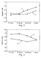
- Figure 2 is a chart of the roughness of two zinc powders identified herein as powder A and powder B.
- Powder A was purchased from N.V. UMICORE, S.A., in Brussels, Belgium and is identified as BIA 115.
- This zinc powder is an alloy that contains 100 ppm bismuth, 200 ppm indium, and 100 ppm aluminum.
- the powder's D 50 which is a measurement used to characterize the powder's particle size, was approximately 115.
- a centrifugal atomization process as generally described in WO 00/48260, which published on August 17, 2000 , was used to produce the zinc powder.
- Powder B had the same alloy composition as powder A and was also purchased from UMICORE.
- Powder B was produced in a gas atomization process which is a conventional manufacturing process used to produce powder from a stream of molten zinc.
- a third process used to manufacture zinc powder is known as impulse atomization and is described in WO 2004/012886 .
- the data in Fig. 2 was generated by using screens to sieve zinc powders that were produced in either a centrifugal atomization process or a gas atomization process.
- the powders were sieved as received from the manufacturer thereby segregating each of the powders into four groups based on particle size range. The ranges were 45 to 75 microns, 75 to 105 microns, 105 to 150 microns and greater than 150 microns.
- the roughness of each segregated group was then characterized using two dimensional image analysis.
- the image analysis technique used an Olympus SZX12 microscope in combination with a digital camera to photograph zinc particles under sufficient magnification to allow the perimeter of individual particles to be accurately measured.
- the technique involved evenly distributing a plurality of particles on a piece of glass which was then placed within the viewing field of the microscope with transmitted light illuminating the particles. The particles were arranged to minimize or eliminate particle to particle contact.
- the magnification of the microscope was selected to allow at least ten pixels for small particles.
- Digital pictures were then taken of different areas of the sample. Each picture had to contain at least two particles that did not touch another particle. Multiple pictures were taken to obtain 1000 images of particles that did not contact another particle.
- Microsuite software produced by Olympus America Inc. of Melville, New York, was used to process the data.
- the roughness index of each group was determined by analyzing images of 1000 particles. For each particle, the roughness was determined by dividing the perimeter of the particle's image by the perimeter of that particle's equivalent ellipse which is defined as an ellipse that has the same area as the particle and its major axis is equal to the longest dimension of the particle's image.
- the roughness index for each group was calculated by averaging the roughness values of the 1000 particles. A higher roughness index means that the particles are rougher than particles with a lower roughness index. As can be seen in Fig 2 , three of the four groups in powder A had a higher average roughness index value than the corresponding groups in powder B.
- the particles in powder A that were separated into the 105 to 150 micron range had an average roughness index value (1.220) that was approximately 3.4 percent higher than the average roughness index value (1.180) of the corresponding group from powder B.
- the particles in powder A that were separated into the group consisting of particles greater than 150 microns had an average roughness index value (1.245) that was approximately 2.9 percent higher than the average roughness index value (1.210) of the corresponding group from powder B.
- the average roughness index differential between two powders useful in a cell of this invention is at least 2.0 percent, more preferably 3.0 percent, even more preferably 3.5 percent.
- Fig 3 is a chart of the elongation index values of the two zinc powders previously identified as powder A and powder B.
- the elongation of 1000 particles from each group in powders A and B were characterized using the two dimensional image analysis equipment described above.
- the elongation index value of each particle was calculated by dividing the major axis of the equivalent ellipse by the Heywood's diameter of the particle's image.
- the Heywood diameter is the diameter of a circle that has an area that is equivalent to the area of the particle's image.
- the average elongation index value for each group was determined by averaging the individual elongation values for the 1000 particles in that group's sample.
- an average elongation index differential between two powders useful in cell of this invention is at least 3.0 percent, more preferably 3.5 percent, even more preferably 4.0 percent.
- the particle size distribution of the blended zinc powder that is obtained by blending the selected first powder and second powder is known to significantly influence the processability and discharge efficiency of the cell containing the blended zinc.
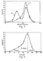
- Zinc powders, that have a particle size distribution with a single apex are known herein as unimodal particle size distribution zinc powders.
- line 80 is an example of a unimodal particle size distribution. If a zinc powder has a particle size distribution with two or more peaks that define a trough therebetween, the zinc powder is known herein as a multimodal particle size distribution zinc powder.
- line 82 is an example of a multimodal particle size distribution.
- Zinc powders with a unimodal particle size distribution are often preferred over zinc powders with a multimodal particle size distribution because unimodal powders are easier to process.
- Multimodal powders that contain a high percentage of zinc fines inherently increase the viscosity of the gelled anode that contains the multimodal powder. The increase in viscosity can cause processing problems in the anode distribution and dispensing equipment that is used to transport and dispense the anode.
- the first and second zinc powders used in a cell of this invention are zinc alloys.
- the alloys contain the same chemical elements, such as bismuth, indium and aluminum, and the quantities of the chemical elements in each alloy are the same.
- a cell of this invention includes a first zinc powder that has a unimodal particle size distribution but at least one selected portion of the distribution has been replaced with a similar distribution of zinc particles from a second zinc powder.
- the particles from the second zinc powder have higher average roughness value than the powders in the first powder that have been replaced.
- Fig. 5 shows a distribution of zinc powders that has been divided into three selected portions.
- the first portion includes particles that flowed through a screen that has 75 micron openings.
- the second portion includes particles that flowed through a screen that has 150 micron openings but did not flow through a screen with 75 micron openings.
- the third portion includes particles that would not flow through a screen with 150 micron openings.
- Blended zinc powders useful in a cell of this invention can be obtained by replacing a selected portion of a zinc powder that has a lower average roughness value with a selected portion of a different zinc powder that has a higher average roughness index value.
- the particle size distribution of the selected portion of zinc powder does not overlap the particle size distribution of the zinc powder with which it is blended.
- a first particle size distribution is considered not to overlap a second particle size distribution if the first distribution is screened or otherwise segregated using a state of the art commercially available process that is at least 98 % effective, based on the weights of the zinc powders before and after screening, in limiting the powder's particle sizes within the desired particle size ranges.
- Another blended zinc powder useful in a cell of this invention could be obtained by replacing a selected portion of a zinc powder that has a higher average roughness index value with a selected portion of a different zinc powder that has lower average roughness index value. Regardless of which powder is segregated into one or more groups that are then blended with one or more groups from another powder, the net result is a blended zinc powder that has had a selected portion, based on particle size distribution and surface roughness, of its zinc particles replaced with particles from another zinc powder's selected portion.
- a blended zinc powder is produced by blending a selected group from a first powder with a second powder that has not been segregated into groups based on surface roughness and particle size range.
- the particles in the first powder's selected group have an average roughness index value that is at least two percent higher than the average roughness index value of the particles in the second powder from the same particle size range which is known herein as the "common" particle size range. For example, if the particles from the first powder's selected group have a particle size range between 75 microns and 105 microns and the second powder has at least some of its particles in the 75 to 105 micron range, then the first and second powder have particles in a common particle size range.
- This embodiment provides for the blending of a selected "common” group from a first powder with a second powder having particles in the same "common” particle size range as the first powder's provided the particles from the first powder are rougher than the particles in the second powder's common particle size range.
- a blended zinc powder useful in a cell of this invention can be obtained by mixing two zinc powders that have essentially the same particle size distributions but the average roughness and/or elongation index values of the first powder's selected portion is higher than the average roughness and/or elongation index values of the same selected portion in the second zinc powder.
- the particle size distribution of the blended zinc powder is the same as the particle size distributions of the two powders that are blended but the blended powder contains particles that are rougher and/or more elongated that the particles in one of the powders.
- Blending zinc powders that have different roughness and/or elongation index values provides cell manufacturers with the ability to tailor the cost-to-performance characteristics of the blended zinc powder. For example, if a first zinc powder is know to provide superior service in an electrochemical cell but the powder is more expensive than another zinc powder which provides less run time, the cell manufacturer can elect to remove a selected portion of the less expensive powder and replace it with a portion of the more expensive powder. The result is a blended powder that is less expensive than the more expensive powder and, as shown in Fig. 6 , the service performance of the cells containing the blended zinc may be equal to or better than the service performance of the cells that contain only the more expensive zinc.
- the ability to tailor the cost-to-performance ratio of the blended powder provides the cell designer with an option that is not available with unblended zinc powders.
- a process that can be used to produce blended zinc powders for use in a cell of this invention includes the following steps. Segregating a first powder into at least two groups based on particle size. Segregating a second powder into at least two groups based on particle size. Wherein at least one group from the first powder and one group from the second powder have a common particle size range and the particles in the first powder's common particle size range have an average roughness index value that is at least 2.0 percent higher than the average roughness index value of the particles in the second powder's common particle size range. Then blending at least one group from the first powder with at least one group from the second group thereby forming a blended zinc powder.
- blended zinc powder when used in the phrase "blended zinc powder" is intended to describe two or more zinc powders that have been mixed, tumbled, stirred or otherwise physically agitated to provide a homogenous distribution of zinc particles from the two or more zinc powders.
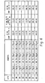
- A.A size batteries having a cell construction similar to that shown in Fig 1 and described above, were manufactured and discharged on three high rate discharge tests.
- the cathodes, separators, electrolyte, seal assemblies and anode formulas, other than the zinc powder, used in each cell were identical.
- the zinc powders used in each lot were obtained as follows.
- a first zinc powder, designated earlier as powder A, was obtained from UMICORE. This powder was an alloy of zinc containing 100 ppm bismuth, 200 ppm indium and 100 ppm aluminum, as previously described. The powder was produced in a centrifugal atomization process and had a D 50 of 115 microns.
- Powder A was screened to produce a first group, designated A-1, with particles that passed through a screen with 75 micron openings, a second group, designated A-2, with particles that did flow through a screen with 150 micron openings but would not flow through a screen with 75 micron openings, and a third group, designated A-3, with particles that would not flow through a screen with 150 micron openings.
- a second powder, designated earlier as powder B was also obtained from UMICORE. This powder, which was an alloy of zinc containing 100 ppm of bismuth, 200 ppm of indium and 100 ppm of aluminum, was produced in a centrifugal atomization process and had a D 50 of 160 microns.
- Powder B was also screened to produce a first group, designated B-1, with particles that passed through a screen with 75 micron openings, a second group, designated B-2, with particles that did flow through a screen with150 micron openings but would not flow through a screen with 75 micron openings, and a third group, designated B-3, with particles that would not flow through a screen with 150 micron openings.
- Eight different blended zinc powders, designated lots 100 to 107 in Fig 6 were obtained by blending various combinations of the groups from the two zinc powders. Lot 100 contained only zinc powder from powder B. Lot 101 contained groups A-1, B-2 and B-3. In this blend, the particle size range of the particles from powder A was less than the particle size range of the particles from powder B.
- Lot 102 contained groups B-1, A-2 and B-3.
- Lot 103 contained groups B-1, B-2 and A-3.
- Lot 104 contained groups B-1, A-2 and A-3.
- Lot 105 contained groups A-1, B-2 and A-3.
- Lot 106 contained groups A-1, A-2 and B-3.
- Lot 107 contained groups A-1, A-2 and A-3.
- the data in Fig 6 was obtained by discharging five batteries from each lot in each of the following three discharge tests which were all done in a 21°C environment. In the first discharge test, each cell was discharged continuously at one amp until the cell's closed circuit voltage dropped below 1.0 volt. In the second discharge test, each cell was discharged repeatedly at one watt for three seconds and then allowed to rest for seven seconds.
- the data in Fig 6 clearly shows that the cells that contained blended zinc powder (lots 101 through 106, inclusive) provided substantially higher service than the cells that contained only powder B (lot 100) and, furthermore, the cells that contained the blended zinc powder provided more minutes of run time than the cells that contained only powder A on both the one amp continuous test and the one watt continuous test.
- the range of run times in lots 101 through 106 demonstrate that the mixing of groups of zinc powders, segregated by particle size distributions, provides cell manufacturers with the ability to choose the desired level of run time by selecting which groups to combine into a blended zinc powder.
Landscapes
- Chemical & Material Sciences (AREA)
- Chemical Kinetics & Catalysis (AREA)
- Electrochemistry (AREA)
- General Chemical & Material Sciences (AREA)
- Engineering & Computer Science (AREA)
- Manufacturing & Machinery (AREA)
- Battery Electrode And Active Subsutance (AREA)
- Primary Cells (AREA)
- Powder Metallurgy (AREA)
Applications Claiming Priority (2)
| Application Number | Priority Date | Filing Date | Title |
|---|---|---|---|
| US10/878,223 US7364819B2 (en) | 2004-06-28 | 2004-06-28 | Alkaline electrochemical cell with a blended zinc powder |
| EP05767792A EP1769549B1 (de) | 2004-06-28 | 2005-06-24 | Elektrochemische alkalizelle mit zinkpudergemisch |
Related Parent Applications (1)
| Application Number | Title | Priority Date | Filing Date |
|---|---|---|---|
| EP05767792.4 Division | 2005-06-24 |
Publications (2)
| Publication Number | Publication Date |
|---|---|
| EP2226873A2 true EP2226873A2 (de) | 2010-09-08 |
| EP2226873A3 EP2226873A3 (de) | 2012-02-01 |
Family
ID=34979487
Family Applications (3)
| Application Number | Title | Priority Date | Filing Date |
|---|---|---|---|
| EP10156076A Withdrawn EP2226873A3 (de) | 2004-06-28 | 2005-06-24 | Elektrochemische Alkalizelle mit einem Zinkpulvergemisch |
| EP05767792A Expired - Lifetime EP1769549B1 (de) | 2004-06-28 | 2005-06-24 | Elektrochemische alkalizelle mit zinkpudergemisch |
| EP10156061A Withdrawn EP2202827A3 (de) | 2004-06-28 | 2005-06-24 | Elektrochemische Alkalizelle mit einem Zinkpulvergemisch |
Family Applications After (2)
| Application Number | Title | Priority Date | Filing Date |
|---|---|---|---|
| EP05767792A Expired - Lifetime EP1769549B1 (de) | 2004-06-28 | 2005-06-24 | Elektrochemische alkalizelle mit zinkpudergemisch |
| EP10156061A Withdrawn EP2202827A3 (de) | 2004-06-28 | 2005-06-24 | Elektrochemische Alkalizelle mit einem Zinkpulvergemisch |
Country Status (7)
| Country | Link |
|---|---|
| US (4) | US7364819B2 (de) |
| EP (3) | EP2226873A3 (de) |
| JP (2) | JP5244387B2 (de) |
| CN (2) | CN101944622B (de) |
| AT (1) | ATE489736T1 (de) |
| DE (1) | DE602005024966D1 (de) |
| WO (1) | WO2006012313A1 (de) |
Families Citing this family (15)
| Publication number | Priority date | Publication date | Assignee | Title |
|---|---|---|---|---|
| US7364819B2 (en) * | 2004-06-28 | 2008-04-29 | Eveready Battery Company, Inc. | Alkaline electrochemical cell with a blended zinc powder |
| EP1715536A3 (de) | 2005-04-20 | 2007-10-10 | ReVolt Technology AS | Zinkelektrode mit einem organischen Geliermittel und einem organischen Bindemittel. |
| JP4199811B2 (ja) * | 2007-01-15 | 2008-12-24 | パナソニック株式会社 | アルカリ乾電池 |
| JP4352349B2 (ja) * | 2008-01-23 | 2009-10-28 | トヨタ自動車株式会社 | 電極および電極製造方法 |
| WO2012114407A1 (ja) * | 2011-02-22 | 2012-08-30 | パナソニック株式会社 | アルカリ二次電池 |
| US10804535B2 (en) | 2012-11-28 | 2020-10-13 | The Government Of The United States Of America, As Represented By The Secretary Of The Navy | Zinc electrodes for batteries |
| US10763500B2 (en) | 2012-11-28 | 2020-09-01 | The Government Of The United States Of America, As Represented By The Secretary Of The Navy | Zinc electrodes for batteries |
| US10720635B2 (en) | 2012-11-28 | 2020-07-21 | The Government Of The United States Of America, As Represented By The Secretary Of The Navy | Zinc electrodes for batteries |
| CN103071786B (zh) * | 2012-12-28 | 2016-01-20 | 深圳市中金岭南科技有限公司 | 一种碱性锌锰电池用锌粉及其制备方法 |
| CN103785825B (zh) * | 2014-01-16 | 2015-10-14 | 超威电源有限公司 | 一种铅酸蓄电池的铅粉生产工艺 |
| KR102725568B1 (ko) * | 2017-10-30 | 2024-11-05 | 더 거버먼트 오브 더 유나이트 스테이츠 오브 아메리카 애즈 레프리젠티드 바이 더 씨크리터리 오브 더 네이비 | 배터리용 아연 전극 |
| US11069889B2 (en) | 2019-07-19 | 2021-07-20 | The Government of the United Stales of America, as represented by the Secretare of the Navy | Zinc electrode improvements |
| TW202130023A (zh) * | 2019-10-04 | 2021-08-01 | 美商澤洛斯能源有限公司 | 具有離子交換材料的電極組件 |
| CN115058784B (zh) * | 2022-06-24 | 2023-09-08 | 灵氟隆新材料科技江苏有限公司 | 一种高质量密度均匀度的聚四氟乙烯扁平长丝制备方法 |
| US12537204B2 (en) | 2022-11-21 | 2026-01-27 | Energizer Brands, Llc | Hybrid material anode current collector for alkaline batteries |
Citations (6)
| Publication number | Priority date | Publication date | Assignee | Title |
|---|---|---|---|---|
| US6022639A (en) | 1996-11-01 | 2000-02-08 | Eveready Battery Company, Inc. | Zinc anode for an electochemical cell |
| WO2000048260A1 (en) | 1999-02-09 | 2000-08-17 | N.V. Union Miniere S.A. | Centrifugally atomized zinc alloy powder for alkaline batteries |
| US6284410B1 (en) | 1997-08-01 | 2001-09-04 | Duracell Inc. | Zinc electrode particle form |
| WO2003043103A2 (en) | 2001-11-12 | 2003-05-22 | Eveready Battery Company, Inc. | Nonwoven separator for electrochemical cell |
| US20040013940A1 (en) | 2002-07-19 | 2004-01-22 | Horn Quinn C. | Electrode for an electrochemical cell and process for making the electrode |
| WO2004012886A2 (en) | 2002-08-05 | 2004-02-12 | Noranda Inc. | Zinc powders for use in electrochemical cells |
Family Cites Families (20)
| Publication number | Priority date | Publication date | Assignee | Title |
|---|---|---|---|---|
| JPH02270164A (ja) | 1989-04-11 | 1990-11-05 | Citizen Watch Co Ltd | インデックス信号発生方式 |
| JP3215447B2 (ja) | 1991-03-12 | 2001-10-09 | 三洋電機株式会社 | 亜鉛アルカリ電池 |
| JP3215446B2 (ja) | 1991-03-12 | 2001-10-09 | 三洋電機株式会社 | 亜鉛アルカリ電池 |
| JP3215448B2 (ja) | 1991-03-12 | 2001-10-09 | 三洋電機株式会社 | 亜鉛アルカリ電池 |
| JPH10334909A (ja) * | 1997-05-30 | 1998-12-18 | Fuji Elelctrochem Co Ltd | アルカリ電池用負極亜鉛基合金粉 |
| US6521378B2 (en) | 1997-08-01 | 2003-02-18 | Duracell Inc. | Electrode having multi-modal distribution of zinc-based particles |
| US6472103B1 (en) | 1997-08-01 | 2002-10-29 | The Gillette Company | Zinc-based electrode particle form |
| US6015636A (en) | 1998-06-01 | 2000-01-18 | Electric Fuel Ltd. | Enhanced performance zinc |
| JP3532797B2 (ja) | 1999-05-21 | 2004-05-31 | 三井金属鉱業株式会社 | 亜鉛合金粉及びそれを用いたアルカリ電池 |
| ES2188539T3 (es) | 1999-06-30 | 2003-07-01 | Grillo Werke Ag | Mezcla de particulas de metales y/o aleaciones y de un medio electrolitico liquido, asi como procedimiento para su preparacion. |
| AU4306301A (en) | 1999-12-02 | 2001-06-12 | Zinc Corporation Of America | Zinc-containing powders and methods of manufacture |
| JP2002270164A (ja) | 2001-03-09 | 2002-09-20 | Mitsui Mining & Smelting Co Ltd | 亜鉛合金粉及びこれを用いたアルカリ電池 |
| US6872489B2 (en) | 2002-02-27 | 2005-03-29 | Rovcal, Inc. | Alkaline cell with gassing inhibitors |
| EP1356881A1 (de) | 2002-04-25 | 2003-10-29 | Grillo-Werke AG | Zinkpulver oder Zinklegierungspulver für alkalische Batterien |
| US6746509B2 (en) | 2002-09-11 | 2004-06-08 | Mitsui Mining & Smelting Company, Ltd. | Process for producing zinc or zinc alloy powder for battery |
| JP4565222B2 (ja) * | 2003-02-20 | 2010-10-20 | Dowaエレクトロニクス株式会社 | アルカリ電池用亜鉛合金粉末とそれを用いたアルカリ電池 |
| JP2004296327A (ja) * | 2003-03-27 | 2004-10-21 | Toshiba Battery Co Ltd | アルカリ電池 |
| AR045347A1 (es) * | 2003-08-08 | 2005-10-26 | Rovcal Inc | Celda alcalina de alta capacidad |
| US7364819B2 (en) * | 2004-06-28 | 2008-04-29 | Eveready Battery Company, Inc. | Alkaline electrochemical cell with a blended zinc powder |
| JP5152773B2 (ja) * | 2005-02-03 | 2013-02-27 | 日立マクセルエナジー株式会社 | アルカリ電池 |
-
2004
- 2004-06-28 US US10/878,223 patent/US7364819B2/en not_active Expired - Lifetime
-
2005
- 2005-06-24 AT AT05767792T patent/ATE489736T1/de not_active IP Right Cessation
- 2005-06-24 WO PCT/US2005/022531 patent/WO2006012313A1/en not_active Ceased
- 2005-06-24 DE DE602005024966T patent/DE602005024966D1/de not_active Expired - Lifetime
- 2005-06-24 EP EP10156076A patent/EP2226873A3/de not_active Withdrawn
- 2005-06-24 CN CN201010287187XA patent/CN101944622B/zh not_active Expired - Lifetime
- 2005-06-24 EP EP05767792A patent/EP1769549B1/de not_active Expired - Lifetime
- 2005-06-24 EP EP10156061A patent/EP2202827A3/de not_active Withdrawn
- 2005-06-24 CN CN2005800216626A patent/CN1977409B/zh not_active Expired - Lifetime
- 2005-06-24 JP JP2007519308A patent/JP5244387B2/ja not_active Expired - Lifetime
-
2008
- 2008-02-21 US US12/035,115 patent/US7718316B2/en not_active Expired - Lifetime
-
2010
- 2010-03-25 US US12/731,214 patent/US8017271B2/en not_active Expired - Lifetime
-
2011
- 2011-08-05 US US13/198,807 patent/US8202651B2/en not_active Expired - Lifetime
-
2012
- 2012-06-26 JP JP2012156951A patent/JP5701257B2/ja not_active Expired - Lifetime
Patent Citations (6)
| Publication number | Priority date | Publication date | Assignee | Title |
|---|---|---|---|---|
| US6022639A (en) | 1996-11-01 | 2000-02-08 | Eveready Battery Company, Inc. | Zinc anode for an electochemical cell |
| US6284410B1 (en) | 1997-08-01 | 2001-09-04 | Duracell Inc. | Zinc electrode particle form |
| WO2000048260A1 (en) | 1999-02-09 | 2000-08-17 | N.V. Union Miniere S.A. | Centrifugally atomized zinc alloy powder for alkaline batteries |
| WO2003043103A2 (en) | 2001-11-12 | 2003-05-22 | Eveready Battery Company, Inc. | Nonwoven separator for electrochemical cell |
| US20040013940A1 (en) | 2002-07-19 | 2004-01-22 | Horn Quinn C. | Electrode for an electrochemical cell and process for making the electrode |
| WO2004012886A2 (en) | 2002-08-05 | 2004-02-12 | Noranda Inc. | Zinc powders for use in electrochemical cells |
Non-Patent Citations (1)
| Title |
|---|
| B. F. GOODRICH, PERFORMANCE MATERIALS DIVISION |
Also Published As
| Publication number | Publication date |
|---|---|
| US20110287307A1 (en) | 2011-11-24 |
| DE602005024966D1 (de) | 2011-01-05 |
| ATE489736T1 (de) | 2010-12-15 |
| EP2202827A3 (de) | 2012-02-01 |
| WO2006012313A1 (en) | 2006-02-02 |
| JP2008504666A (ja) | 2008-02-14 |
| JP5701257B2 (ja) | 2015-04-15 |
| US20080193849A1 (en) | 2008-08-14 |
| JP2013041818A (ja) | 2013-02-28 |
| JP5244387B2 (ja) | 2013-07-24 |
| US20100178558A1 (en) | 2010-07-15 |
| EP1769549B1 (de) | 2010-11-24 |
| US8202651B2 (en) | 2012-06-19 |
| EP1769549A1 (de) | 2007-04-04 |
| CN1977409A (zh) | 2007-06-06 |
| US7364819B2 (en) | 2008-04-29 |
| EP2202827A2 (de) | 2010-06-30 |
| EP2226873A3 (de) | 2012-02-01 |
| US7718316B2 (en) | 2010-05-18 |
| US8017271B2 (en) | 2011-09-13 |
| CN101944622B (zh) | 2013-04-03 |
| CN101944622A (zh) | 2011-01-12 |
| CN1977409B (zh) | 2011-09-14 |
| US20060005663A1 (en) | 2006-01-12 |
Similar Documents
| Publication | Publication Date | Title |
|---|---|---|
| US8017271B2 (en) | Alkaline electrochemical cell with a blended zinc powder | |
| JP5453243B2 (ja) | アルカリ化学電池 | |
| EP2254178B1 (de) | Elektrode mit partikeln auf zink-basis | |
| US6521378B2 (en) | Electrode having multi-modal distribution of zinc-based particles | |
| JP2007515757A (ja) | 電気化学セル | |
| JP2022510543A (ja) | 二重アノードを有するアルカリ電池 | |
| EP1683218A2 (de) | Elektrochemische alkali-zelle | |
| WO2003090956A1 (en) | Zinc powder or zinc alloy powder for alkaline batteries | |
| EP2022117A2 (de) | Batterieanoden | |
| EP1794826A1 (de) | Elektrochemische alkalizelle | |
| WO2004010513A2 (en) | Electrode for an electrochemical cell and process for making the electrode | |
| US7556888B2 (en) | Electrochemical cell | |
| WO2023228802A1 (ja) | アルカリ乾電池 | |
| WO2023228800A1 (ja) | アルカリ乾電池 |
Legal Events
| Date | Code | Title | Description |
|---|---|---|---|
| PUAI | Public reference made under article 153(3) epc to a published international application that has entered the european phase |
Free format text: ORIGINAL CODE: 0009012 |
|
| AC | Divisional application: reference to earlier application |
Ref document number: 1769549 Country of ref document: EP Kind code of ref document: P |
|
| AK | Designated contracting states |
Kind code of ref document: A2 Designated state(s): AT BE BG CH CY CZ DE DK EE ES FI FR GB GR HU IE IS IT LI LT LU MC NL PL PT RO SE SI SK TR |
|
| PUAL | Search report despatched |
Free format text: ORIGINAL CODE: 0009013 |
|
| AK | Designated contracting states |
Kind code of ref document: A3 Designated state(s): AT BE BG CH CY CZ DE DK EE ES FI FR GB GR HU IE IS IT LI LT LU MC NL PL PT RO SE SI SK TR |
|
| RIC1 | Information provided on ipc code assigned before grant |
Ipc: B22F 1/00 20060101AFI20111229BHEP Ipc: H01M 4/12 20060101ALI20111229BHEP Ipc: H01M 6/08 20060101ALI20111229BHEP Ipc: H01M 4/24 20060101ALI20111229BHEP |
|
| 17P | Request for examination filed |
Effective date: 20120725 |
|
| 17Q | First examination report despatched |
Effective date: 20120911 |
|
| STAA | Information on the status of an ep patent application or granted ep patent |
Free format text: STATUS: THE APPLICATION IS DEEMED TO BE WITHDRAWN |
|
| 18D | Application deemed to be withdrawn |
Effective date: 20130322 |