EP2226895A2 - Antenne pour la réception circulaire dans un sens de rotation de la polarisation de signaux radio par satellite rayonnés - Google Patents
Antenne pour la réception circulaire dans un sens de rotation de la polarisation de signaux radio par satellite rayonnés Download PDFInfo
- Publication number
- EP2226895A2 EP2226895A2 EP10001881A EP10001881A EP2226895A2 EP 2226895 A2 EP2226895 A2 EP 2226895A2 EP 10001881 A EP10001881 A EP 10001881A EP 10001881 A EP10001881 A EP 10001881A EP 2226895 A2 EP2226895 A2 EP 2226895A2
- Authority
- EP
- European Patent Office
- Prior art keywords
- antenna
- loop
- radiator
- loop antenna
- phase
- Prior art date
- Legal status (The legal status is an assumption and is not a legal conclusion. Google has not performed a legal analysis and makes no representation as to the accuracy of the status listed.)
- Granted
Links
Images














Classifications
-
- H—ELECTRICITY
- H01—ELECTRIC ELEMENTS
- H01Q—ANTENNAS, i.e. RADIO AERIALS
- H01Q7/00—Loop antennas with a substantially uniform current distribution around the loop and having a directional radiation pattern in a plane perpendicular to the plane of the loop
-
- H—ELECTRICITY
- H01—ELECTRIC ELEMENTS
- H01Q—ANTENNAS, i.e. RADIO AERIALS
- H01Q21/00—Antenna arrays or systems
- H01Q21/24—Combinations of antenna units polarised in different directions for transmitting or receiving circularly and elliptically polarised waves or waves linearly polarised in any direction
-
- H—ELECTRICITY
- H01—ELECTRIC ELEMENTS
- H01Q—ANTENNAS, i.e. RADIO AERIALS
- H01Q21/00—Antenna arrays or systems
- H01Q21/29—Combinations of different interacting antenna units for giving a desired directional characteristic
-
- H—ELECTRICITY
- H01—ELECTRIC ELEMENTS
- H01Q—ANTENNAS, i.e. RADIO AERIALS
- H01Q9/00—Electrically-short antennas having dimensions not more than twice the operating wavelength and consisting of conductive active radiating elements
- H01Q9/04—Resonant antennas
- H01Q9/30—Resonant antennas with feed to end of elongated active element, e.g. unipole
- H01Q9/32—Vertical arrangement of element
-
- H—ELECTRICITY
- H01—ELECTRIC ELEMENTS
- H01Q—ANTENNAS, i.e. RADIO AERIALS
- H01Q9/00—Electrically-short antennas having dimensions not more than twice the operating wavelength and consisting of conductive active radiating elements
- H01Q9/04—Resonant antennas
- H01Q9/30—Resonant antennas with feed to end of elongated active element, e.g. unipole
- H01Q9/32—Vertical arrangement of element
- H01Q9/36—Vertical arrangement of element with top loading
Definitions
- the invention relates to an antenna for receiving circularly in a direction of rotation of the polarization of radiated satellite radio signals
- Satellite radio signals are transmitted due to polarization rotations in the transmission path usually with circularly polarized electromagnetic waves.
- program contents are transmitted, for example, in frequency bands closely adjacent to each other separated frequency bands, as in FIG. 1 is shown. This is done in the example of SDARS satellite broadcasting at a frequency of about 2.33 GHz in two adjacent frequency bands each with a bandwidth of 4 MHz with a spacing of the center frequencies of 8 MHz.
- the signals are emitted by different satellites with a circularly polarized in one direction electromagnetic wave.
- circularly polarized antennas are used to receive in the corresponding direction of rotation.
- Such antennas are for example off DE-A-4008505 and DE-A-10163793 known.
- This satellite broadcasting system is additionally supported by the regional emission of terrestrial signals in another, arranged between the two satellite signals frequency band of the same bandwidth. Similar satellite broadcasting systems are currently being planned.
- the from the DE-A-4008505 known antenna is constructed on a substantially horizontally oriented conductive base and consists of crossed horizontal dipoles with V-shaped downwardly inclined, consisting of linear ladder parts Dipolhhann which are mechanically fixed at an azimuthal angle of 90 degrees to each other and at the top of a on the conductive base surface mounted linear vertical conductor are mounted.
- the from the DE-A-10163793 known antenna is also constructed on a generally horizontally oriented conductive base and consists of crossed azimuthally mounted at 90 ° to each other frame structures. In both antennas, the mutually spatially offset by 90 ° antenna parts in the electrical phase are interconnected shifted by 90 ° to each other to generate the circular polarization.
- Both types of antennas are particularly suitable for the reception of satellite signals emitted by high-flying satellites - so-called HEOS.
- the signals of geostationary satellites - known as GEOS - are incident at lower elevation angles in regions remote from the equatorial zones.
- the reception of such signals is possible with the two antenna types mentioned only with comparatively small antenna gain and therefore problematic due to the - due to economic reasons - weak transmitter power of the satellites. Added to this is the difficulty of designing antennas with a smaller height, which is imperative especially for mobile applications.
- As further antennas of this type are known in the prior art patch antennas, which are also less efficient in terms of the reception at a low elevation angle.
- the object of the invention is therefore to provide an antenna with a low profile, which is particularly suitable for the powerful reception of incident at low elevation angles circularly polarized in one direction of rotation emitted satellite signals.
- an antenna of this type is advantageously combined in a common space with antenna structures, which also receive a circularly polarized field and which together with these antenna structures in an antenna diversity system or a system for digital beam shaping Azimuthal beam swing can be used.
- This combination is particularly interesting for receiving systems in which signals from GEO satellites and HEO satellites in closely adjacent frequency bands are to be received equally.
- the antenna combination is characterized by a particularly low mutual coupling of the antennas with each other.
- the antenna for receiving circularly polarized satellite radio signals comprises at least two emitters connected to an antenna connector 28, each linearly polarized in a spatial direction and connected via a matching and phase shifter network 25, 31, and is characterized in that one of the emitters is formed as a loop antenna 14 substantially arranged in a horizontal plane conductor loop and the loop antenna 14 for their electrically effective shortening at least one bridged by a capacitor 16 interruption 5, in particular a plurality of spaced apart, bridged by capacitances 16 interruptions. At least one interruption 5 of the conductor loop forms a loop antenna connection point 3 of the loop antenna 14.
- At least one further radiator 7 is present, which has a linear polarization and with its radiator junction 2 and with the loop antenna connection point 3 via a matching and phase shifting network 25, 23 is connected, which is so formed that, in reciprocal operation of the antenna as transmitting antenna, the radiation fields of the loop antenna 14 and the at least one further radiator 7 are superimposed in the far field of the antenna with different phases.
- This at least one of the further radiators 7 has a polarization oriented perpendicular to the polarization of the loop antenna 14. All radiators are essentially formed of slender wire-like conductors similar ladder structures.
- antennas which from the DE-A-4008505 and the DE-A-10163793 Problems arise from the fact that the individual antenna parts are placed on crossed at a right angle planes and these levels in addition to the conductive ground plane stand vertically.
- Such antennas can not be produced sufficiently economically, as desired, for example, for use in the automotive industry. This applies in particular to the frequencies of several gigahertz common in satellite antennas, for which a particularly high mechanical accuracy is necessary in the interest of polarization R unit, the impedance matching and the reproducibility of the directional diagram in the series production of the antennas.
- the required in antennas according to the present invention manufacturing tolerances can be maintained in an advantageous manner much easier.
- Another very important advantage of the present invention results from the property that in addition to the horizontally polarized loop antenna 14 at least one further radiator 7 is present, which has a polarization oriented perpendicular to the polarization of the loop antenna 14. In the presence of terrestrially vertically polarized signals, this emitter can advantageously also be used to receive these signals.
- the distribution of the currents on an antenna in receive mode depends on the terminator at the antenna junction.
- the distribution of the currents on the antenna conductors relative to the supply current at the antenna connection point is independent of the source resistance of the supplying signal source and is thus clearly linked to the directional diagram and the polarization of the antenna.
- the object of the invention with respect to polarization and radiation patterns on the basis of the design of the antenna structure for generating corresponding currents in the transmission mode of Antenna solved.
- the object of the invention for the receiving operation is solved. All considerations made below about currents on the antenna structure and their phases or their phase reference point thus refer to the reciprocal operation of the receiving antenna as a transmitting antenna, unless the receiving mode is specifically addressed.
- the object of the invention is directed to a receiving antenna, the properties of the antenna are described below for better traceability for the reciprocal operation of the antenna as a transmitting antenna, the transmission case but also applies to the directional diagrams of the receiving case due to the naturally valid reciprocity relationship.
- the property is that according to the reciprocity law when operating the antenna as a transmitting antenna in the far field generated electric field strength vector even at relatively low elevation angles of the radiation describes a purely circular circular polarization with azimuthal omnidirectional in the technical sense.
- phase-locked combination of the horizontally polarized loop antenna 14 with the at least one vertical emitter 7 is done by superposition of the distant radiation fields of the two emitters by 90 ° by correspondingly different phase supply and corresponding amplitude supply of the two antennas.
- the distant radiation field in a plane perpendicular to the direction of propagation two mutually perpendicular and by 90 ° in phase differing field strength vectors are generated, which represent the desired circularly polarized field.
- the phase reference points B - or else the phase centroids - of the two antennas coincide, which is achieved by rotationally symmetrical arrangement about the common center Z of the antennas.
- the circular or polygonal loop antenna 14 arranged horizontally in a plane with a constant spacing 4 as the height h above the base surface 6.
- This acts essentially similar to a loop antenna over a conductive surface.
- the elevation angle of the main beam direction can be adjusted by selecting the height h and the horizontal extent-that is, the radius in a circular design of the loop antenna 14. In this case, a zero point in the vertical direction and in the horizontal direction can be achieved.
- the achievement of a desired vertical directional pattern requires a horizontal extension of the loop antenna such that its total orbital length is no longer small compared to the free-space electrical wavelength ⁇ 0 .
- the loop antenna into n equal portions of the cable length .DELTA.s is therefore ⁇ 0/8 divided by break points 5 ', which are connected to each other by inserting a capacitor.
- the capacitances are preferably selected such that resonances occur at the operating frequency fm together with the properties of the line sections.
- Such an antenna can advantageously for an azimuthally pure Rund characterizing be designed.
- the at least one vertical radiator 7, which in the example of the Fig.2 is present in the center Z of the loop antenna 14 and whose azimuthal radiation pattern is also omnidirectional, resulting for the antenna according to the invention, the desired circularly polarized radiation field with pure omnidirectional.
- the antenna according to the invention is advantageously suitable in particular for satellite radio reception in vehicles, where antennas with azimuthal omnidirectional characteristics are mounted on the electrically conductive vehicle outer skin.
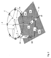
- Fig. 2 shows a circular loop antenna 14 with radius R, which may also be designed polygonal. At its center in the center Z is its phase reference point B. The structure is subdivided into "n" line sections, each with the length ⁇ s. The total orbital length is S. The antenna acts as a loop antenna with dimensions in the range of the wavelength, wherein nevertheless a homogeneous current distribution is achieved by dividing the structure and inserting capacitances 16 according to the invention. As a result, the length of the antenna is electrically shortened and creates a homogeneous, horizontally polarized electromagnetic field all around.
- the loop antenna 14 is arranged at a constant height h above the conductive base 6. The main vertical beam direction can be adjusted by selecting the height h and the radius of the loop antenna 14. It can be achieved a zero point in the vertical direction and in the horizontal direction.
- the conductor impedance of the circulating line over the conductive base 6 is Zw.
- resonance can be set for the loop antenna 14, so that the antenna impedance occurring at the loop antenna connection point 3 can be made substantially real.
- the line of length S is to be divided into a sufficient number of sections by insertion of capacitances 16.
- .DELTA.s S / n made sufficiently small, so the equality is .DELTA.s all sections not necessarily required, as long as a capacitor 16 is inserted only after each section whose value-described upward criterion of the relative length .DELTA.s / ⁇ 0 of the calculated section.
- radiator 7 is in the example of Fig. 2 in the center Z of the loop antenna 14, an electrically short, vertically oriented monopole 7a attached.
- the deviation of the positioning of the monopole 7a from the center Z should not exceed in the interest of circularity of the radiation pattern of ⁇ 0 / 20th
- a matching network 25 with Umsymmetrierglied 29 and a switched after phase shifter network 23 are connected via a two-wire line 26.
- the radiator junction 2 of the monopole 7a is followed by the matching network 25 for impedance matching and the signals of the monopole 7a and the loop antenna are superimposed in the summing network 53; this in turn is connected to the antenna connection point 28.
- the phase of the phase shifter network 23 and all the networks are adjusted in their interaction such that the radiation fields of the loop antenna 14 and the monopole 7a in the far field of the antenna with a phase difference of 90 ° and with equal intensity are superimposed.
- the latter is designed according to the invention in such a way that it acts inductively high impedance with respect to the current flowing in the common mode longitudinal current, which is superimposed on the current in the push-pull current pair on the two conductors. It is thereby achieved that the two-wire line 26 does not influence the radiation field of the monopole 7a.
- a two-wire line 26 there are a number of possibilities. In practice, for example, it can be advantageously produced by a printed on a support two-wire line, which is designed to increase the inductance as a meander. Additionally, by choosing its length, a desired phase relationship can be established.
- the vertical radiation pattern can be filled to low elevation angles for these signals.
- the trained as a rod antenna monopole 7a has in its vertical directional characteristic a similar main beam direction as the horizontally polarized loop antenna 14, but provides for low elevation angle a larger contribution than this.
- both the weighting of the properties of the two antenna signals can be set differently and additionally the necessary phase condition can be maintained.
- the influence of a symmetrical vertical feed line not in the center Z in the form of the symmetrical two-wire line 26 does not diminish the polarization purity of the loop antenna 14 itself.
- the connection of one terminal on the unbalanced side of the matching and Umsymmetrierglieds 25, 29 for further switching of the antenna assembly is advantageously carried out using a guided over the conductive base 6 microstrip line 30.
- the other terminal on the unbalanced side of Umsymmetrierglieds 29 is electrically connected to the conductive base 6 connected. Due to the symmetry properties of the two-wire line 26, the effects of the currents flowing toward one another in the opposite direction compensate each other sufficiently on the conductors of the two-wire line 26, so that these also do not influence the radiation properties of the loop antenna 14. As explained below, are However, with respect to the azimuthal radiation pattern of the monopole 7a, depending on the radius R of the loop antennas 14, a residual imbalance may occur.
- both the axial ratio and the spatial orientation of the ellipse for elliptical polarization can be adjusted.
- This adjustability can according to the invention in a very advantageous manner, for.
- antenna diversity technologies are used to continuously optimize the receive power by current adjustment of the ellipticity of the polarization in the distorted by multipath propagation reception field.
- a horizontally arranged loop antenna 14 is placed at a distance of about 1/10 of the wavelength above the conductive base 6.
- the diameter of the loop antenna 14 is advantageously not chosen substantially smaller than 1/4 of the wavelength.
- one with a capacity 16 with a reactance of about -200 ohms connected interruption point 5 is introduced at intervals of about 1/8 of the wavelength.
- the loop antenna 14 By virtue of the capacitances 16 according to the invention, it is possible on the loop antenna 14 to achieve an azimuthally constant current distribution necessary for the round radiation, although the stretched length of the loop antennas 14 is not short in comparison to the wavelength ⁇ . On the other hand, this length is again necessary to effect a practical impedance of the loop antenna 14.
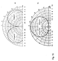
- Figure 15 (a) For example, the vertical diagram of such an antenna according to the invention is shown.
- the loop antenna 14 has an edge length of about 3 cm and a height h of 13 mm for the realization of both of the vertical directional diagram Fig. 15 (a) as well as a matching conductor characteristic impedance Zw proved to be favorable.
- the satellite broadcasting system is additionally supported by the regionally radiating vertically polarized terrestrial signals in another frequency band closely adjacent to the frequency band of similar bandwidth, it is desirable to use the vertical radiation pattern for the vertical component of the electric field strength at low elevation angles fill.
- the connection according to the invention of the loop antenna 14 and of the further polarized further radiator 7 - mostly realized as a vertical monopole - allows this aspect to be considered in a particularly advantageous manner.
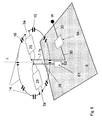
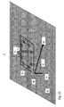
- Fig. 3 an antenna according to the invention is shown, wherein the further radiator 7, which is oriented perpendicular to the plane of the loop antenna 14, is formed from a group of monopoles 7a. These are arranged rotationally symmetrical to the center Z and within the loop antenna 14. The monopolies are connected to each other at their lower end via lines in the center Z and form there the radiator junction 2. In the not too large diameter of the annulus on which the monopoles 7a are arranged around the center Z and 7a is not too small number of monopolies the azimuthal directional diagram of the thus designed radiator 7 sufficiently omnidirectional.
- Fig. 4 shows an advantageous embodiment of an antenna according to the invention similar to in FIG. 2 , wherein the loop antenna 14 for reducing the residual asymmetry of the arrangement with respect to the azimuthal directional diagram of the monopole 7 has two antenna connection points 3a, 3b opposite each other in the plane of symmetry SE, to which balancing and matching networks 25, 29 arranged in the loop plane are connected, their outputs via same phase shifter networks 23 are connected in parallel and connected to the two-wire line 26.
- the arranged in the center Z further radiator 7 is designed as a monopoly 7b with horizontal, rotationally symmetrical to the center Z arranged ladder parts as roof capacity. These ladder parts are symmetrical to the plane of symmetry SE executed.
- a further advantageous embodiment of the invention is similar to that shown in Figure four, but with conductor parts of the loop antenna 14 are used to form the rotationally symmetrical roof capacity 12.
- the function of the loop antenna 14 is not affected by the connection of the roof capacitance 12 of the monopoly.
- Fig. 14 is the antenna according to the invention as in Fig. 5 illustrated, but with a common radiator junction 2 for the common feed of the loop antenna 14 and the vertical monopoly with roof capacity 7b.
- the circularly polarized field is formed by splitting the waves incident on the vertical monopole antenna and the horizontal arms of the roof capacitance 12 on the loop antenna 14 right and left, the distance to the next capacitance 16 on the loop antenna being to the right is selected differently than the distance to the next capacitance 16 on the loop antenna towards the left side.
- the loop antenna is thus so to rotate around the z-axis against the Dachkapazi2011 that arise on the left and right sides different angular distances ⁇ and ⁇ between the horizontal arms of the roof capacity and the next capacity.
- FIG. 6 shows a further advantageous embodiment of the invention according to the principle of operation of the antenna in Fig. 2 but with a vertical feed line 26 arranged in the center Z for supplying the loop antenna 14, the feed line 26 forming a vertical monopole 7a and the loop antenna 14 forming a roofing capacity 12 of the monopole 7.
- the loop antenna 14 is formed with two antenna connection points 3a, 3b arranged symmetrically to one another and one matching network 25 each in the loop plane and with a central connection to the vertical feed line to the matching network 33, which is designed as a two-wire line 26.
- the effects of the currents of the loop antenna 14 flowing in push-pull mode in the opposite direction compensate each other on the conductors of the two-wire line 26.
- the reception voltage of the monopole 7a becomes at its radiator junction 2 as a common mode of the two-wire line 26 at one output and the receiving voltage of the loop antenna 14th is supplied as a push-pull mode of the two-wire line 26 at the other output of the matching network 33 to the power divider and phase shifter network 31 for amplitude and phase-different superposition of the signals at the antenna port 28.
- Fig. 7 shows a further advantageous embodiment of the antenna according to the principle of operation of the antenna in Fig. 6 , but with a designed as a square with the center Z loop antenna 14, which by four arranged in a square, horizontally disposed and connected at their ends via capacitances 16 dipoles 21 with a connected via leads 18, centrally in the Phase reference point B arranged distribution network 10 is formed.
- the dipole system acts as a roofing capacity of the vertical monopole formed in this manner, similar to FIG FIG. 5 explained.
- the reception of horizontal or vertical electric field components is effected via the summation 34 or the difference formation 35 and the phase-different superimposition of the signals via the phase shifter network 23 and the summation network 53.
- a further advantageous embodiment of the invention is in Fig. 8 an antenna arrangement shown with phase-different superposition of the received voltages from the horizontal and the vertical electric field components of a loop antenna 14 and a monopole antenna 7a formed by the vertical two-wire line 26. Similar to in Fig. 4 Here again, in order to improve the symmetry of the arrangement, two antenna connection points 3a, 3b with matching networks 25 in the plane of the loop antenna 14 are present in the plane of symmetry SE.
- the adjustment of the common mode to normal ratio on the vertical two-wire line 26 takes place, whereby the ratio of the portion of the vertically polarized low elevation field of the main beam direction to the portion of the horizontally polarized field Field with higher elevation of the main beam direction is set.
- the adjustment of the phases necessary for the generation of the circular polarization takes place with the aid of this summing network 53.
- the axial ratio and the spatial orientation of the ellipse for elliptical polarization can be set by selecting the above-mentioned common-mode-to-differential ratio and the phase adjustment ,
- the antenna is similar to the embodiment as in FIG. 2 - But designed as a multi-frequency area antenna.
- the capacitances 16 are each formed in each case from identical bipolar networks, preferably each consisting of a circuit comprising a plurality of dummy elements. So that's different Operating frequencies different capacitance values effective, which allow the resonance for the design of the real antenna impedance at these different operating frequencies.
- FIG. 1 is the situation shown that two satellite radio frequency bands with small bandwidth Bu or Bo closely adjacent at a high frequency in the L-band or in the S-band, at least at a frequency of fm> 1 GHz with the same directions, ie z , B. left-rotating circular polarization (LHCP) are radiated.
- LHCP left-rotating circular polarization
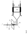
- Fig. 10 shows an antenna arrangement with a vertically polarized monopole 7 formed as a rod antenna and a horizontally polarized loop antenna 14 according to the invention with respect to the transmission case common phase reference point B, but with separate supply of signals to the terminal for vertical polarization 49 and for connection for horizontal polarization 48th Der At these terminals, connected hybrid couplers 45 with 90 ° positive and negative phase difference with respect to the LHCP terminal 28a and the RHCP terminal 28b enables the separate availability of LHCP or RHCP signals of different circular polarization directions of rotation.
- the monopole 7 embodied as a rod antenna 32 has an interruption point 5 connected to a dummy element 8 in order to design its vertical diagram.
- the one substantially perpendicular monopole 7 contains at least one interruption point 5 which connects or bridges with the design of the vertical diagram with at least one dummy element 8 is.
- the vertical diagram can be advantageously adapted to the requirements.
- the antenna connection point 2 is formed at the base of the monopole 7 at the connection to the matching network 33.
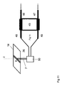
- FIG. 11 A similar antenna arrangement is in Fig. 11 however, the realization of the monopole 7 is similar to the antenna arrangement in FIG. 10 by the combination of acting as a roof capacitance loop antenna 14 and the two-wire line 26 takes place.
- a combined matching circuit 50 By means of a combined matching circuit 50, both the adaptation of the loop antenna 14 and the adjustment of the monopole 7 as well as the setting of a common phase reference point B are created.
- a loop antenna 14 - as in FIG. 6 - Provided with two opposing antenna connection points 3a, 3b and connected thereto and located in the loop level matching networks 25, which are implemented, for example, as ⁇ / 4 transformation lines.
- the outputs of the matching networks 25 are connected in parallel in addition.
- the received signal is fed via the two-wire line 26 to a matching network 25 located on the base area 6, the output of which is in turn connected to one of the two inputs of a signal combination circuit designed in particular as a 90 ° hybrid coupler 45.
- the antenna arrangement can also advantageously be used for polarization diversity by switching between reception for LHCP and RHCP waves.
- FIG. 13 In a further particularly economical embodiment of such an antenna with circularly polarized field with reversible direction of rotation is in FIG. 13 - similar to the antenna in FIG. 12 -
- the separate monopoly 7 saved.
- the two-wire line 26 For the reception with vertical polarization is also the two-wire line 26 - similar to FIG. 8 - exploited.
- the difference of 90 ° between the phases of the horizontal field component picked up by the vertical two-wire line 26 with the loop antenna 14 as the roof capacitance 12 and that picked up by the loop antenna 14 is set their combination with this phase difference is present at the microstrip conductor 30 to the matching network 54 and thus also at the junction 28.
- the antenna receives a circularly polarized field.
- a circuit combining the receive signals of the loop antenna 14 at the output of the matching networks 25 from the horizontally polarized electric field and the receiving signals of the vertical two-wire line 26 from the vertically polarized electric field comprises an LHCP / RHCP switch 55 for reversing the polarity of the receiving voltage of the loop antenna 14.
- the latter can be added in this way with different signs of the received voltage from the vertically polarized electric field, so that between the reception of the LHCP field and the RHCP field by switching the LHCP / RHCP switch 55 can be switched.
- Triggered by a switchover control between LHCP and RHCP received signals located in the receiver signals of differently polarized polarization of the satellite signals are available alternately on different transmission paths.
- the antenna in FIG. 8 explained - can also be a corresponding network 61 of reactances in the ground connected strand of the vertical two-wire line 26 are switched.
- the adjustment of the common mode to differential ratio on the vertical two-wire line 26 can be set.
- the received voltages from the horizontal and the vertical electric field components are superimposed phase-differently according to the circular polarization.
- the common-mode to differential ratio on the vertical two-wire line 26 the ratio of the low-polarization vertically-polarized field of the main beam direction to the proportion of the higher polarization horizontally-polarized field of the main beam direction can be adjusted.
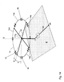
- the antenna is combined with another azimuth circular radiator whose circular polarization is circular and the circular polarization phase rotates with the azimuthal angle of the propagation vector - ie, a complete azimuthal revolution the angle 2 ⁇ .
- the antenna is combined with another azimuth circular radiator whose circular polarization is circular and the circular polarization phase rotates with the azimuthal angle of the propagation vector - ie, a complete azimuthal revolution the angle 2 ⁇ .
- FIG. 15a is the vertical directional characteristic of the LHCP polarized electromagnetic field of a previously described inventive antenna shown.
- the phase of this field is independent of the azimuthal angle and thus the phase for the azimuthal angles 0 ° and 180 ° are each marked with the same angle - in the example 0 °.
- the antenna gain of the combined antenna arrangement can increase 0 ° for the azimuthal angle and weaken 180 ° for the azimuthal angle and even adjust a zero point of the directional diagram with a suitable adjustment of the amplitudes at a desired elevation angle, as in Fig. 16 is shown.
- the azimuthal directional diagram while maintaining the elevation directional diagram, results from the same angle .phi., In .sup.-, due to the phase change of the circular polarization of the crossed emitter (7d) with the azimuthal angle of the propagation vector turned one way or the other.
- the directional diagram of the combined antenna arrangement in mobile use advantageously z. B. be tracked with his main direction pointing to the satellite or, for example, a disturber by directional assignment of the zero point of the directional diagram are selectively hidden.
- satellite reception on vehicles can hereby be in the context of a dynamically tracked setting of the directional diagram, the signal-noise ratio while driving optimally designed.
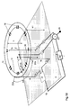
- Fig. 17 the combined antenna arrangement according to the invention is shown with a crossed emitter 7b indicated by the construction space 42, as it is described, for example, in US Pat EP 1 239 543 B1 , there in Fig. 10a , is shown.
- the vertical antenna conductor 20 indicated there is here in FIG Fig. 17 is executed as an equivalent vertical monopole 7a in the center Z and is decoupled from the junction 56 of the crossed radiator 49 due to symmetry conditions.
- the latter is connected via the controllable phase shifter 39 to the summing network 53, in which the signals of the loop antenna 14, the vertical monopole 7a and the crossed emitter 49 are combined with the respectively suitable weighting to the received signal of the combined antenna arrangement.
- an antenna of the type shown in FIG DE-A-4008505 or a patch antenna with the vertical monopole 7a in the center Z, as well as an arrangement over the ground plane of parallel crossed dipoles are combined.
- All arrangements of n equal horizontal radiating elements 59 can be used for this, if they are arranged so that their centers give the corners of an equilateral polygon, and if the rotation of the arrangement about the z-axis by an angle of 360 ° / n, the structure in depicts itself and if the feed in each case in the direction of rotation of adjacent radiator elements differs in phase by 360 ° / n.
- Fig. 25 Such arrangements are shown respectively for the example of four and five radiator elements.
- a novel radiator 7c with circular polarization and azimuthal omnidirectional diagram, the phase of which rotates with the azimuthal angle of the propagation vector, is hereinafter referred to as ring line radiator 7c designated used.
- ring line radiator 7c designated used.
- FIG. 15 (b) For example, the vertical diagram of such an antenna according to the invention is shown.
- the ring line radiator 7c is arranged as a polygonal or circular, arranged rotationally symmetrically about the center Z Ring line in a horizontal plane with the height h1 extending over the conductive base 6, designed.
- the ring line is fed in such a way that it adjusts the current distribution of a current line wave whose phase difference over a cycle is just 2 ⁇ , thus the elongated length of the ring line corresponds to the wavelength ⁇ , which adjusts itself to the ring line.
- the radiation contributions of the horizontally polarized individual conductor sections are superimposed in the far field in such a way that the desired radiation with circular polarization and the required phase dependence adjusts itself to the azimuthal propagation direction and the substantially omnidirectional azimuthal directional characteristic.
- D ⁇ / ⁇ .
- the wavelength ⁇ on the loop is equal to the free space wavelength ⁇ 0 .
- the wavelength ⁇ on the loop can be made by increasing the line inductance and / or the line capacitance to the conductive base 6. This can be done in a known per se, for example, preferably by introducing concentrated inductive elements in the line structure or, for example by meandering design of the ring conductor.
- Fig. 18 shows such a combined antenna arrangement, consisting of the loop antenna 14 and the combined with a phase difference monopole 7a for generating the circularly polarized radiation field with azimuthal independent phase position and a concentric with center Z arranged circular ring radiator 7c with loop connection point 19 for superimposing its circular polarized radiation field, however, with azimuthally dependent phase position and to control the azimuthal main direction via the controllable phase shifter 39.
- the phase center of the ring line radiator 7c is due to the described phase distribution on the rotationally symmetric loop structure in the center Z of the antenna array and thus falls with the described phase reference point B of the loop antenna 14th and that of the monopole 7a together - regardless of the position of the controllable phase shifter 39.
- Ring line radiator 7c takes place starting from the ring line connection point 19 via the power divider and phase shifter network 31, at whose outputs are shifted by 90 ° to each other in phase signals, which in each case via a matching network 25 via the leads 18 to ⁇ / 4 apart ring line Supply points 22a and 22b are connected along the loop structure.
- a ring line radiator 7c of this type has the particular advantage that it is concentric with the loop antenna 14 and designed in comparison to this with a larger diameter.
- a transverse dimension which is customary for the loop antenna 14 can be designed within wide limits, but is generally smaller than ⁇ / 4 and can therefore be designed within the ring line radiator 7c with a diameter ⁇ / ⁇ .
- the diameters of the two emitters can be designed within wide limits independently of each other in the interest of designing their vertical directional patterns and the resulting vertical directional pattern of the antenna array at the antenna port 28.
- the distance h of the plane of the loop antenna 14 from the conductive base 6 from the distance h1 between the plane of the loop emitter 7c and the conductive base 6 can be chosen to be different, although it is particularly economical to manufacture if both emitters are in printed form, for example printed on the same sheet carrier.
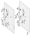
- FIG 16 (a) is an example of the vertical diagram and in Fig. 16 (b) the horizontal diagram of such an antenna according to the invention is shown.
- the loop antenna 14 has an edge length of about 3 cm and a height h of 13 mm and for the square shaped loop emitter has an edge length of about 3.4 cm, which corresponds to about 1 ⁇ 4 of the wavelength, and a height h of 10 mm for the realization of both the directional diagram according to Fig. 16 proved favorable.
- the loop antenna 14 is connected via the common-mode high-resistance two-wire line 26 via a matching network 25 and the monopole 7a is connected via a matching network 25 and via the phase shifter network 23 to the summing network 53 to form the circularly polarized radiation with azimuthal phase independence.
- the ring line connection point 19 is connected via the controllable phase shifter 39 to the summation network 53 and the signals are superimposed there with the appropriate weight for generating the desired vertical directional diagram of the antenna arrangement with adjustable azimuthal main direction at the antenna port 28 the other signals.
- the generation of the continuous line shaft on the ring line radiator 7c takes place in accordance with FIG. 18 but through the ⁇ / 4 coupling conductor 43 in FIG FIG. 20 , This is performed in a respect to the line impedance characteristic distance over a straight length of ⁇ / 4 parallel to the ring line radiator 7c.
- the ⁇ / 4 coupling conductor 43 can be economically applied to the same carrier as the ring line radiator 7c and optionally the loop antenna 14 printed.
- the generation of the continuous line shaft takes place on the ring line radiator 7c in accordance with FIG. 20 however, by ⁇ / 4 directional coupler 44 in FIG FIG. 21 , To a microstrip conductor 30, a ⁇ / 4-coupling conductor 43 is guided in parallel, which forms the ⁇ / 4-directional coupler 44 together with the coupled to the ring line radiator 7c ⁇ / 4-coupler 43.
- the ring line radiator 7c is similar to an antenna as in FIG. 18 , but formed as a closed square line ring over the conductive base 6 with the edge length of ⁇ / 4 in a plane at a distance h1 above the conductive base 6.
- the loop antenna 14 is arranged with its capacitances 6 as a square conductor structure within the ring line radiator 7c with the same center Z. The remaining antennas are not shown for reasons of clarity.
- the ramped ⁇ / 4 coupling conductor 43 is in FIG. 22 the ramped ⁇ / 4 coupling conductor 43 to emphasize.
- a vertical feed line 18 leads to a coupling spacing 58 at one of the corners, from where it essentially meets the base area 6 according to a ramp function below an adjacent corner in order to electrically connect with the latter to be connected.
- This form of coupling is particularly advantageous for economic production because, due to the square design of the ring line radiator 7c, the ramped ⁇ / 4 coupling conductor 43 can be designed on a planar support.
- impedance matching at the ring line connection point 19 can also be brought about in an advantageous manner.
- the ring line radiator 7c is designed as square as in FIG. 22 , However, is fed at its corners in each case via a feed line 18, which runs in each case over an equal length as a microstrip conductor 30 on the conductive base surface 6 and which each contains an equally long vertical conductor. The remaining antennas are not shown for reasons of clarity.
- the supply lines 18 are - starting from the ring line connection point 19 - connected to a power distribution network, which consists of connected in chain ⁇ / 4-long microstrip conductors 30 (15a, 15b, 15c).
- the characteristic impedances of the microstrip conductors 30 are - starting from a low characteristic impedance at the ring line connection point 19 - to which one of the supply lines 18 is directly connected - stepped up in such a way that the signals fed in at the corners into the ring line radiator 7c have the same powers and in each case by 90 ° in the phase continuously lagging differ.
- the remaining antenna parts are also not shown for reasons of clarity.
- an advantageous extension of the invention is in the antenna in FIG. 24 another radiator in the form of an outer ring channel radiator 7e present.
- the ring line radiator 7c whose circumference corresponds to exactly one wavelength ⁇ -ie one full period-the circumference of the outer ring channel radiator 7e is selected to be two wavelengths ⁇ , so that upon excitation with signals shifted in phase by 90 ° to one another at ⁇ / 4 spaced loop feeders 22 along the outer loop structure adjusts a continuous line wave on the loop emitter 7d.
- This feed takes place in the example in FIG. 24 in both loops in a similar manner via the matching networks 25 and the power divider and phase shifter network 31.
- the junction 21 of the outer loop radiator 7e is also connected to the summing network 53, so that the effects of the radiation of the outer outer ring radiator 7e depending on the weight Antenna connector 28 occur.
- the signals at the loop antenna monopole connection point 27, at the ring line connection point 19 and at the connection point 21 of the outer loop emitter 7e are weighted together via controllable phase shifters 39 in the summation network 53, so that at the antenna connection 28 in the set azimuthal main direction increased antenna gain is achieved. Due to the larger diameter of the outer ring line radiator 7e, its contribution is more sharply focused than that of the circularly polarized ring line 7c. Although the polarization is no longer purely circular by connecting the outer loop emitter 7e, the radiation gain for certain situations can be increased by this measure due to the overall sharper focusing.
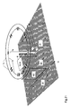
- FIG. 26 instead of the ring line radiator 7c in FIG. 22 a circle group radiator 7f from the in FIG. 25 described type shown.
- This consists of several in a parallel to the conductive base 6 and at a distance to this arranged plane and around the center Z azimuth rotationally symmetrical on a circle K. arranged horizontally polarized radiator elements 59. Via leads 18 with phase shifter network a common circular array radiator junction 60 is provided.
- each radiating element 59 is energized with a current of equal amplitude but phase-wise such that the magnitude of the current phase equals the azimuth angle ⁇ originating from an azimuthal reference line the azimuthal position of the radiator element 59 is selected so that the current phase increases or decreases with increasing azimuth angle ⁇ .
- the horizontally polarized radiator elements 59 are arranged at the vertices of a square with center Z and oriented in each case perpendicular to the connecting lines between the relevant vertex and the center Z.
- the horizontally polarized radiator elements 59 are each connected via an equally long lead 18 to the terminals of a power divider and phase shifter network.
- the latter is made of chain-connected formed on the conductive base 6 ⁇ / 4-long microstrip conductors 30 with the sections 15a, 15b, 15c, whose characteristic impedance - starting from a low characteristic impedance at the circular array radiator junction 60 - to which one of the leads 18 is directly connected - are staggered in such a way that the signals fed at the corners in the radiating elements 59 have the same powers and each lag 90 ° in the phase continuously lag.
Landscapes
- Variable-Direction Aerials And Aerial Arrays (AREA)
Applications Claiming Priority (1)
| Application Number | Priority Date | Filing Date | Title |
|---|---|---|---|
| DE102009011542A DE102009011542A1 (de) | 2009-03-03 | 2009-03-03 | Antenne für den Empfang zirkular in einer Drehrichtung der Polarisation ausgestrahlter Satellitenfunksignale |
Publications (3)
| Publication Number | Publication Date |
|---|---|
| EP2226895A2 true EP2226895A2 (fr) | 2010-09-08 |
| EP2226895A3 EP2226895A3 (fr) | 2010-12-15 |
| EP2226895B1 EP2226895B1 (fr) | 2013-04-10 |
Family
ID=42245979
Family Applications (1)
| Application Number | Title | Priority Date | Filing Date |
|---|---|---|---|
| EP10001881.1A Active EP2226895B1 (fr) | 2009-03-03 | 2010-02-24 | Antenne pour la réception circulaire dans un sens de rotation de la polarisation de signaux radio par satellite rayonnés |
Country Status (3)
| Country | Link |
|---|---|
| US (1) | US8537063B2 (fr) |
| EP (1) | EP2226895B1 (fr) |
| DE (1) | DE102009011542A1 (fr) |
Cited By (11)
| Publication number | Priority date | Publication date | Assignee | Title |
|---|---|---|---|---|
| EP2296227A3 (fr) * | 2009-09-10 | 2011-06-29 | Delphi Delco Electronics Europe GmbH | Antenne pour la réception de signaux satellite circulaires polarisés |
| WO2012123125A1 (fr) * | 2011-03-15 | 2012-09-20 | Delphi Deutschland Gmbh | Antenne de réception multibande pour la réception combinée de signaux satellites et de signaux radiophoniques à émission terrestre |
| WO2013119410A1 (fr) * | 2012-02-02 | 2013-08-15 | Harris Corporation | Dispositif de communication sans fil doté d'une antenne cadre pourvue de quatre points de couplage distants et d'un réflecteur et procédés associés |
| WO2014031303A1 (fr) * | 2012-08-22 | 2014-02-27 | Symbol Technologies, Inc. | Agencement d'antenne co-localisé |
| EP2858175A1 (fr) * | 2013-10-01 | 2015-04-08 | Seiko Epson Corporation | Antenne et appareil électronique |
| CN110212304A (zh) * | 2018-02-28 | 2019-09-06 | 丰田自动车株式会社 | 阵列天线 |
| CN114122684A (zh) * | 2020-08-30 | 2022-03-01 | 华为技术有限公司 | 天线装置和无线设备 |
| US11262431B2 (en) * | 2014-09-22 | 2022-03-01 | Symbol Technologies, Llc | Co-located locationing technologies |
| CN115966894A (zh) * | 2023-03-17 | 2023-04-14 | 广东工业大学 | 一种超宽带双圆极化天线 |
| WO2023139122A1 (fr) * | 2022-01-19 | 2023-07-27 | Fuba Automotive Electronics Gmbh | Module d'antenne pour un récepteur destiné à assurer la réception mobile de signaux de satellites de localisation |
| CN119362024A (zh) * | 2024-12-30 | 2025-01-24 | 南湖实验室 | 一种小型水平极化全向天线 |
Families Citing this family (41)
| Publication number | Priority date | Publication date | Assignee | Title |
|---|---|---|---|---|
| SG192021A1 (en) * | 2011-01-27 | 2013-08-30 | Galtronics Corp Ltd | Broadband dual-polarized antenna |
| US20130201065A1 (en) * | 2012-02-02 | 2013-08-08 | Harris Corporation | Wireless communications device having loop antenna with four spaced apart coupling points and associated methods |
| US20130201070A1 (en) * | 2012-02-02 | 2013-08-08 | Harris Corporation | Wireless communications device having loop waveguide transducer with spaced apart coupling points and associated methods |
| RU2515551C2 (ru) * | 2012-05-10 | 2014-05-10 | Олег Кириллович Апухтин | Способ поворота плоскости поляризации радиоволны |
| CN102882004B (zh) * | 2012-06-29 | 2016-08-03 | 华为技术有限公司 | 一种电磁耦极子天线 |
| RU2012154791A (ru) * | 2012-08-09 | 2014-10-27 | Дмитрий Витальевич Татарников | Антенная система (варианты) |
| WO2014034490A1 (fr) * | 2012-08-27 | 2014-03-06 | 日本電業工作株式会社 | Antenne |
| WO2014110508A1 (fr) * | 2013-01-11 | 2014-07-17 | Chi-Chih Chen | Antennes à ultralarge bande et à entrée multiple sortie multiple |
| US8923452B2 (en) * | 2013-03-18 | 2014-12-30 | Lockheed Martin Corporation | Noise-based gain adjustment and amplitude estimation system |
| GB2512111B (en) * | 2013-03-20 | 2017-02-15 | British Broadcasting Corp | Antenna arrangement for transmitting two or more polarisations of radio signal |
| US20140312834A1 (en) * | 2013-04-20 | 2014-10-23 | Yuji Tanabe | Wearable impact measurement device with wireless power and data communication |
| US10158178B2 (en) * | 2013-11-06 | 2018-12-18 | Symbol Technologies, Llc | Low profile, antenna array for an RFID reader and method of making same |
| US9847571B2 (en) * | 2013-11-06 | 2017-12-19 | Symbol Technologies, Llc | Compact, multi-port, MIMO antenna with high port isolation and low pattern correlation and method of making same |
| US9847576B2 (en) * | 2013-11-11 | 2017-12-19 | Nxp B.V. | UHF-RFID antenna for point of sales application |
| US9735822B1 (en) * | 2014-09-16 | 2017-08-15 | Amazon Technologies, Inc. | Low specific absorption rate dual-band antenna structure |
| JP6077036B2 (ja) * | 2015-03-18 | 2017-02-08 | 日本電信電話株式会社 | ループアンテナ |
| EP3091610B1 (fr) * | 2015-05-08 | 2021-06-23 | TE Connectivity Germany GmbH | Système d'antenne et module d'antenne à réduction d'interférences entre des motifs rayonnants |
| US9912050B2 (en) * | 2015-08-14 | 2018-03-06 | The Boeing Company | Ring antenna array element with mode suppression structure |
| CN105514613B (zh) * | 2015-08-20 | 2019-06-18 | 广东通宇通讯股份有限公司 | 一种超宽频双极化天线振子 |
| CN107968264B (zh) * | 2016-10-20 | 2020-07-31 | 上海诺基亚贝尔股份有限公司 | 多边形环路天线以及通信设备和天线制造方法 |
| DE102018201580B4 (de) | 2018-02-01 | 2019-11-07 | Fraunhofer-Gesellschaft zur Förderung der angewandten Forschung e.V. | Schaltungsanordnung |
| DE102018211931B4 (de) * | 2018-07-18 | 2025-12-31 | Fraunhofer-Gesellschaft zur Förderung der angewandten Forschung e.V. | Vorrichtung zur Modenverwirbelung |
| US20210135694A1 (en) * | 2018-08-31 | 2021-05-06 | Hach Lange Gmbh | Antenna network matching |
| US11056800B2 (en) * | 2018-10-16 | 2021-07-06 | Google Llc | Antenna arrays integrated into an electromagnetic transparent metallic surface |
| DE102019201262A1 (de) * | 2019-01-31 | 2020-08-06 | Fraunhofer-Gesellschaft zur Förderung der angewandten Forschung e.V. | Teilnehmer eines Kommunikationssystems mit einer magnetischen Antenne |
| KR102236706B1 (ko) * | 2020-01-10 | 2021-04-05 | 경상국립대학교산학협력단 | 근거리 루프 안테나 |
| US11165167B2 (en) * | 2020-02-07 | 2021-11-02 | Deere & Company | Antenna system for circularly polarized signals |
| CN111816992B (zh) * | 2020-06-03 | 2022-12-06 | 昆山睿翔讯通通信技术有限公司 | 一种基于特征模式极化可重构天线实现方法 |
| US11808910B2 (en) * | 2020-07-28 | 2023-11-07 | Saudi Arabian Oil Company | Method and apparatus for looking ahead of the drill bit |
| KR20220034547A (ko) * | 2020-09-11 | 2022-03-18 | 삼성전기주식회사 | 안테나 장치 및 이를 포함하는 전자 장치 |
| FI130161B (en) * | 2020-12-04 | 2023-03-22 | Corehw Semiconductor Oy | CIRCULAR POLARIZED ANTENNAS |
| US11764487B2 (en) * | 2021-03-30 | 2023-09-19 | Rf Venue, Inc. | Diversity antenna with a uniform omnidirectional radiation pattern |
| CN113097700B (zh) * | 2021-04-06 | 2025-07-01 | 北京理工大学 | 一种上半球面全覆盖的全极化天线 |
| US20220345190A1 (en) * | 2021-04-22 | 2022-10-27 | Honeywell International Inc. | Vehicle communication system with dual transmit antennas |
| CN115693112B (zh) * | 2021-07-27 | 2025-07-04 | 华为技术有限公司 | 天线及电子设备 |
| CN115708258B (zh) * | 2021-08-20 | 2026-01-09 | 荣耀终端股份有限公司 | 一种耦合馈电的终端缝隙天线 |
| CN113964504B (zh) * | 2021-09-09 | 2023-01-13 | 华南理工大学 | 一种多边环形双极化高增益宽带基站天线及通信设备 |
| CN114256622B (zh) * | 2021-12-31 | 2025-08-12 | 惠州市德赛西威智能交通技术研究院有限公司 | 一种毫米波阵列平面耦合环状解耦结构及天线阵列 |
| CN114883777B (zh) * | 2022-04-24 | 2024-03-26 | 西安矩阵无线科技有限公司 | 一种高收纳比圆极化天线 |
| CN117080741A (zh) * | 2022-05-09 | 2023-11-17 | 华为技术有限公司 | 一种天线组件及电子设备 |
| US12500333B2 (en) | 2022-11-30 | 2025-12-16 | Deere & Company | Antenna for a satellite receiver |
Citations (2)
| Publication number | Priority date | Publication date | Assignee | Title |
|---|---|---|---|---|
| DE4008505A1 (de) | 1990-03-16 | 1991-09-19 | Lindenmeier Heinz | Antenne fuer die mobile satellitenkommunikation |
| DE10163793A1 (de) | 2001-02-23 | 2002-09-05 | Heinz Lindenmeier | Flachantenne für die mobile Satellitenkommunikation |
Family Cites Families (81)
| Publication number | Priority date | Publication date | Assignee | Title |
|---|---|---|---|---|
| US2217911A (en) * | 1938-08-12 | 1940-10-15 | Rca Corp | Radio communication |
| US2460260A (en) * | 1945-10-03 | 1949-01-25 | Farnsworth Res Corp | Antenna for radiating circularly polarized waves |
| NL71398C (fr) * | 1947-09-01 | |||
| US3623110A (en) * | 1968-09-10 | 1971-11-23 | Sony Corp | Loop antenna with spaced impedance elements |
| US3942119A (en) | 1973-03-02 | 1976-03-02 | Hans Kolbe & Co. | Multiple-transmission-channel active antenna arrangement |
| DE2552049C3 (de) | 1975-11-20 | 1979-01-04 | Hans Heinrich Prof. Dr. 8035 Gauting Meinke | Funkentstörte Empfangsantenne in der Nähe der Heizleiter auf der Fensterscheibe eines Kraftfahrzeuges |
| DE2552002C3 (de) | 1975-11-20 | 1979-07-19 | Gerhard Prof. Dr.-Ing. 8012 Ottobrunn Flachenecker | Funkentstörte Empfangsantenne in der Nähe der Heizleiter auf der Fensterscheibe eines Kraftfahrzeuges |
| US4083051A (en) * | 1976-07-02 | 1978-04-04 | Rca Corporation | Circularly-polarized antenna system using tilted dipoles |
| DE2907369C2 (de) * | 1979-02-24 | 1984-10-18 | Dornier System Gmbh, 7990 Friedrichshafen | Antennenanordnung für Schleppflugkörper |
| JPS5763941A (en) * | 1980-10-06 | 1982-04-17 | Nippon Telegr & Teleph Corp <Ntt> | Radio transmitter and receiver |
| DE3315458A1 (de) | 1983-04-28 | 1984-11-08 | Gerhard Prof. Dr.-Ing. 8012 Ottobrunn Flachenecker | Aktive windschutzscheibenantenne fuer alle polarisationsarten |
| DE3410415A1 (de) | 1984-03-21 | 1985-09-26 | Gerhard Prof. Dr.-Ing. 8012 Ottobrunn Flachenecker | Aktive antenne in der heckscheibe eines kraftfahrzeugs |
| DE3517247A1 (de) | 1985-05-13 | 1986-11-13 | Gerhard Prof. Dr.-Ing. 8012 Ottobrunn Flachenecker | Antennendiversity-empfangsanlage zur elimination von empfangsstoerungen |
| DE3618452C2 (de) | 1986-06-02 | 1997-04-10 | Lindenmeier Heinz | Diversity-Antennenanordnung für den Empfang frequenzmodulierter Signale in der Heckscheibe eines Kraftfahrzeugs mit einem darin befindlichen Heizfeld |
| DE3820229C1 (fr) | 1988-06-14 | 1989-11-30 | Heinz Prof. Dr.-Ing. 8033 Planegg De Lindenmeier | |
| DE3907493A1 (de) | 1989-03-08 | 1990-09-20 | Lindenmeier Heinz | Scheibenantenne mit antennenverstaerker |
| DE3911178A1 (de) | 1989-04-06 | 1990-10-11 | Lindenmeier Heinz | Scheibenantennensystem mit antennenverstaerker |
| US5801663A (en) | 1989-05-01 | 1998-09-01 | Fuba Automotive Gmbh | Pane antenna having at least one wire-like antenna conductor combined with a set of heating wires |
| US5266960A (en) | 1989-05-01 | 1993-11-30 | Fuba Hans Kolbe Co. | Pane antenna having at least one wire-like antenna conductor combined with a set of heating wires |
| DE3914424A1 (de) | 1989-05-01 | 1990-12-13 | Lindenmeier Heinz | Antenne mit vertikaler struktur zur ausbildung einer ausgedehnten flaechenhaften kapazitaet |
| DE4101629C3 (de) | 1991-01-21 | 2003-06-26 | Fuba Automotive Gmbh | Antennendiversity-Anlage mit mindestens zwei Antennen für den mobilen Empfang von Meter- und Dezimeterwellen |
| DE4216377A1 (de) | 1992-05-18 | 1993-11-25 | Lindenmeier Heinz | Funkantennenanordnung in der Nähe von Fahrzeugfensterscheiben |
| DE4318869C2 (de) | 1993-06-07 | 1997-01-16 | Lindenmeier Heinz | Funkantennen-Anordnung auf der Fensterscheibe eines Kraftfahrzeugs und Verfahren zur Ermittlung ihrer Beschaltung |
| DE4441761A1 (de) | 1994-11-23 | 1996-05-30 | Lindenmeier Heinz | Mehrantennen-Scanning-Diversitysystem für Fahrzeuge |
| DE19510236A1 (de) | 1995-03-21 | 1996-09-26 | Lindenmeier Heinz | Flächige Antenne mit niedriger Bauhöhe |
| EP0776530A4 (fr) * | 1995-06-21 | 1998-06-10 | Motorola Inc | Procede et antenne produisant un diagramme de rayonnement omnidirectionnel |
| DE19607045A1 (de) | 1996-02-24 | 1997-08-28 | Lindenmeier Heinz | Empfangsantennen-Scanningdiversitysystem für den Meterwellenbereich für Fahrzeuge |
| DE19612958A1 (de) | 1996-04-01 | 1997-10-02 | Fuba Automotive Gmbh | Antennenverstärker auf einer Fensterscheibe |
| DE19614068A1 (de) | 1996-04-09 | 1997-10-16 | Fuba Automotive Gmbh | Flachantenne |
| DE19618333A1 (de) | 1996-05-07 | 1997-11-13 | Lindenmeier Heinz | Schaltungsanordnung zur Funktionsprüfung mobiler Rundfunkempfangsanlagen |
| US5926141A (en) | 1996-08-16 | 1999-07-20 | Fuba Automotive Gmbh | Windowpane antenna with transparent conductive layer |
| DE19636125B4 (de) | 1996-09-06 | 2007-12-06 | Fuba Automotive Gmbh & Co. Kg | Raumdiversity-Verfahren und -Schaltungsanordnung |
| DE19637327B4 (de) | 1996-09-13 | 2009-04-09 | Delphi Delco Electronics Europe Gmbh | Frequenzdiversity-Anordnung |
| DE19740254A1 (de) | 1996-10-16 | 1998-04-23 | Lindenmeier Heinz | Funkantennen-Anordnung und Patchantenne auf der Fensterscheibe eines Kraftfahrzeuges |
| DE19646100A1 (de) | 1996-11-08 | 1998-05-14 | Fuba Automotive Gmbh | Flachantenne |
| DE59712744D1 (de) | 1996-12-13 | 2006-11-23 | Fuba Automotive Gmbh | Leitungs-Steckverbindung |
| DE19806834A1 (de) | 1997-03-22 | 1998-09-24 | Lindenmeier Heinz | Antennenanlage für den Hör- und Fernsehrundfunkempfang in Kraftfahrzeugen |
| US6130645A (en) | 1998-01-14 | 2000-10-10 | Fuba Automotive Gmbh & Co. Kg | Combination wide band antenna and heating element on a window of a vehicle |
| DE19817573A1 (de) | 1998-04-20 | 1999-10-21 | Heinz Lindenmeier | Antenne für mehrere Funkdienste |
| DE19834577B4 (de) | 1998-07-31 | 2011-12-29 | Delphi Technologies, Inc. | Antennensystem |
| JP2000077934A (ja) * | 1998-08-27 | 2000-03-14 | Yasushi Koshiro | 偏波切替えループアンテナ |
| DE19847653A1 (de) | 1998-10-15 | 2000-04-20 | Heinz Lindenmeier | Einrichtung zur Unterdrückung des Empfangs von fahrzeugemittierter Störstrahlung |
| DE19847887A1 (de) | 1998-10-18 | 2000-04-20 | Heinz Lindenmeier | Scanning-Antennen-Diversity-System für Fahrzeuge |
| DE19854169A1 (de) | 1998-11-24 | 2000-05-25 | Heinz Lindenmeier | Fensterscheibenantenne mit hochfrequent hochohmig angeschlossenem Heizfeld |
| DE19858465A1 (de) | 1998-12-17 | 2000-06-21 | Heinz Lindenmeier | Scanning-Diversity-Antennensystem für Fahrzeuge |
| DE19916855A1 (de) | 1999-04-14 | 2000-10-26 | Heinz Lindenmeier | Funktelefonanlage mit Gruppenantenne für Fahrzeuge |
| DE19930571B4 (de) | 1999-07-02 | 2010-04-29 | Delphi Delco Electronics Europe Gmbh | Diagnosevorrichtung für eine Mehrantennenanordnung |
| DE10033336A1 (de) | 1999-08-11 | 2001-04-12 | Heinz Lindenmeier | Diversityantenne für eine Diversityantennenanlage in einem Fahrzeug |
| DE10010226A1 (de) | 1999-08-31 | 2001-03-01 | Lindenmeier Heinz | Antenne auf dem Fenster eines Kraftfahrzeugs |
| TW432746B (en) * | 1999-11-08 | 2001-05-01 | Acer Neweb Corp | Circular polarization antenna for wireless data communication |
| US6960984B1 (en) * | 1999-12-08 | 2005-11-01 | University Of North Carolina | Methods and systems for reactively compensating magnetic current loops |
| DE10102616A1 (de) | 2000-02-17 | 2001-08-23 | Heinz Lindenmeier | Antennendiversityanlage mit phasengeregelter Summation von Antennensignalen |
| US6262690B1 (en) * | 2000-10-13 | 2001-07-17 | Motorola, Inc. | Method for efficiently generating selectable antenna polarization |
| DE10100812B4 (de) | 2001-01-10 | 2011-09-29 | Heinz Lindenmeier | Diversityantenne auf einer dielektrischen Fläche in einer Fahrzeugkarosserie |
| US6618016B1 (en) * | 2001-02-21 | 2003-09-09 | Bae Systems Aerospace Inc. | Eight-element anti-jam aircraft GPS antennas |
| US6768457B2 (en) | 2001-03-02 | 2004-07-27 | Fuba Automotive Gmbh & Co. Kg | Diversity systems for receiving digital terrestrial and/or satellite radio signals for motor vehicles |
| EP1239608B1 (fr) | 2001-03-02 | 2006-04-19 | FUBA Automotive GmbH & Co. KG | Système en diversité de reception des signaux numeriques terrestre et/ou satellite pour voitures |
| DE10114769B4 (de) | 2001-03-26 | 2015-07-09 | Heinz Lindenmeier | Aktive Breitbandempfangsantenne |
| EP1476764A1 (fr) | 2002-02-22 | 2004-11-17 | DaimlerChrysler AG | Procede et dispositif pour controler au moins une antenne |
| DE10209060B4 (de) | 2002-03-01 | 2012-08-16 | Heinz Lindenmeier | Empfangsantennenanordnung für Satelliten- und/oder terrestrische Funksignale auf Fahrzeugen |
| US6812902B2 (en) * | 2002-05-13 | 2004-11-02 | Centurion Wireless Technologies, Inc. | Low profile two-antenna assembly having a ring antenna and a concentrically-located monopole antenna |
| DE10245813A1 (de) | 2002-10-01 | 2004-04-15 | Lindenmeier, Heinz, Prof. Dr.-Ing. | Aktive Breitbandempfangsantenne mit Empfangspegelregelung |
| DE10258367A1 (de) | 2002-12-12 | 2004-07-08 | Daimlerchrysler Ag | Mehrzielfähiges Verfahren und mehrzielfähige Sensorvorrichtung für die Abstands- und Winkelortung von Zielobjekten im Nahbereich |
| DE10304431A1 (de) | 2003-02-04 | 2004-08-05 | Lindenmeier, Heinz, Prof. Dr.-Ing. | Scanning-Antennen-Diversitysystem für den FM-Hörrundfunk für Fahrzeuge |
| DE10304909B4 (de) | 2003-02-06 | 2014-10-09 | Heinz Lindenmeier | Antenne mit Monopolcharakter für mehrere Funkdienste |
| DE10304911B4 (de) * | 2003-02-06 | 2014-10-09 | Heinz Lindenmeier | Kombinationsantennenanordnung für mehrere Funkdienste für Fahrzeuge |
| US6927735B2 (en) | 2003-02-25 | 2005-08-09 | Fuba Automotive Gmbh & Co. Kg | Antenna arrangement in the aperture of an electrically conductive vehicle chassis |
| JP4297840B2 (ja) * | 2004-06-24 | 2009-07-15 | 古野電気株式会社 | 円偏波ループアンテナ |
| DE102006006266A1 (de) | 2005-02-13 | 2006-08-24 | Lindenmeier, Heinz, Prof. Dr. Ing. | Anlage zum Empfang von digital modulierten Funksignalen zu einem Fahrzeug unter Verwendung von Antennendiversity |
| DE202005008338U1 (de) | 2005-05-24 | 2005-12-22 | Fuba Automotive Gmbh & Co. Kg | Antennenkonfiguration für den Rundfunkempfang in Kfz |
| WO2007011191A1 (fr) * | 2005-07-22 | 2007-01-25 | Electronics And Telecommunications Research Institute | Petite antenne monopôle dotée d’une alimentation de boucle |
| DE102006039357B4 (de) | 2005-09-12 | 2018-06-28 | Heinz Lindenmeier | Antennendiversityanlage zum Funkempfang für Fahrzeuge |
| DE102006057520A1 (de) | 2005-12-15 | 2007-06-21 | Lindenmeier, Heinz, Prof. Dr. Ing. | Empfangsanlage mit Gleichphasung von Antennensignalen |
| DE102007011636A1 (de) | 2007-03-09 | 2008-09-11 | Lindenmeier, Heinz, Prof. Dr. Ing. | Antenne für den Rundfunk-Empfang mit Diversity-Funktion in einem Fahrzeug |
| EP1978647A3 (fr) | 2007-04-05 | 2013-10-09 | Delphi Delco Electronics Europe GmbH | Système de réception à large bande |
| DE102007017478A1 (de) | 2007-04-13 | 2008-10-16 | Lindenmeier, Heinz, Prof. Dr. Ing. | Empfangsanlage mit einer Schaltungsanordnung zur Unterdrückung von Umschaltstörungen bei Antennendiversity |
| DE102008031068A1 (de) | 2007-07-10 | 2009-01-15 | Lindenmeier, Heinz, Prof. Dr. Ing. | Antennendiversityanlage für den relativ breitbandigen Funkempfang in Fahrzeugen |
| DE102007039914A1 (de) | 2007-08-01 | 2009-02-05 | Lindenmeier, Heinz, Prof. Dr. Ing. | Antennendiversityanlage mit zwei Antennen für den Funkempfang in Fahrzeugen |
| DE102008003532A1 (de) | 2007-09-06 | 2009-03-12 | Lindenmeier, Heinz, Prof. Dr. Ing. | Antenne für den Satellitenempfang |
| EP2034557B1 (fr) * | 2007-09-06 | 2012-02-01 | Delphi Delco Electronics Europe GmbH | Antenne pour la réception de satellites |
| DE102008047937A1 (de) | 2008-09-18 | 2010-03-25 | Delphi Delco Electronics Europe Gmbh | Rundfunk-Empfangssystem |
-
2009
- 2009-03-03 DE DE102009011542A patent/DE102009011542A1/de not_active Withdrawn
-
2010
- 2010-02-24 EP EP10001881.1A patent/EP2226895B1/fr active Active
- 2010-03-03 US US12/716,318 patent/US8537063B2/en active Active
Patent Citations (3)
| Publication number | Priority date | Publication date | Assignee | Title |
|---|---|---|---|---|
| DE4008505A1 (de) | 1990-03-16 | 1991-09-19 | Lindenmeier Heinz | Antenne fuer die mobile satellitenkommunikation |
| DE10163793A1 (de) | 2001-02-23 | 2002-09-05 | Heinz Lindenmeier | Flachantenne für die mobile Satellitenkommunikation |
| EP1239543B1 (fr) | 2001-02-23 | 2006-08-09 | FUBA Automotive GmbH & Co. KG | Antenne plate pour communication mobile via satellites |
Cited By (19)
| Publication number | Priority date | Publication date | Assignee | Title |
|---|---|---|---|---|
| US9287623B2 (en) | 2009-09-10 | 2016-03-15 | Delphi Deutschland Gmbh | Antenna for reception of circularly polarized satellite radio signals |
| US8599083B2 (en) | 2009-09-10 | 2013-12-03 | Delphi Delco Electronics Europe Gmbh | Antenna for reception of circularly polarized satellite radio signals |
| EP2296227A3 (fr) * | 2009-09-10 | 2011-06-29 | Delphi Delco Electronics Europe GmbH | Antenne pour la réception de signaux satellite circulaires polarisés |
| US9300047B2 (en) | 2009-09-10 | 2016-03-29 | Delphi Deutschland Gmbh | Antenna for reception of circularly polarized satellite radio signals |
| WO2012123125A1 (fr) * | 2011-03-15 | 2012-09-20 | Delphi Deutschland Gmbh | Antenne de réception multibande pour la réception combinée de signaux satellites et de signaux radiophoniques à émission terrestre |
| US9553365B2 (en) | 2011-03-15 | 2017-01-24 | Delphi Deutschland Gmbh | Multiband reception antenna for the combined reception of satellite signals and terrestrially emitted radio signals |
| WO2013119410A1 (fr) * | 2012-02-02 | 2013-08-15 | Harris Corporation | Dispositif de communication sans fil doté d'une antenne cadre pourvue de quatre points de couplage distants et d'un réflecteur et procédés associés |
| WO2014031303A1 (fr) * | 2012-08-22 | 2014-02-27 | Symbol Technologies, Inc. | Agencement d'antenne co-localisé |
| US8870069B2 (en) | 2012-08-22 | 2014-10-28 | Symbol Technologies, Inc. | Co-located antenna arrangement |
| CN104518277A (zh) * | 2013-10-01 | 2015-04-15 | 精工爱普生株式会社 | 天线以及电子装置 |
| EP2858175A1 (fr) * | 2013-10-01 | 2015-04-08 | Seiko Epson Corporation | Antenne et appareil électronique |
| US10153552B2 (en) | 2013-10-01 | 2018-12-11 | Seiko Epson Corporation | Antenna and electronic apparatus |
| US11262431B2 (en) * | 2014-09-22 | 2022-03-01 | Symbol Technologies, Llc | Co-located locationing technologies |
| CN110212304A (zh) * | 2018-02-28 | 2019-09-06 | 丰田自动车株式会社 | 阵列天线 |
| CN114122684A (zh) * | 2020-08-30 | 2022-03-01 | 华为技术有限公司 | 天线装置和无线设备 |
| WO2023139122A1 (fr) * | 2022-01-19 | 2023-07-27 | Fuba Automotive Electronics Gmbh | Module d'antenne pour un récepteur destiné à assurer la réception mobile de signaux de satellites de localisation |
| CN115966894A (zh) * | 2023-03-17 | 2023-04-14 | 广东工业大学 | 一种超宽带双圆极化天线 |
| CN115966894B (zh) * | 2023-03-17 | 2023-05-12 | 广东工业大学 | 一种超宽带双圆极化天线 |
| CN119362024A (zh) * | 2024-12-30 | 2025-01-24 | 南湖实验室 | 一种小型水平极化全向天线 |
Also Published As
| Publication number | Publication date |
|---|---|
| US20100253587A1 (en) | 2010-10-07 |
| EP2226895B1 (fr) | 2013-04-10 |
| EP2226895A3 (fr) | 2010-12-15 |
| US8537063B2 (en) | 2013-09-17 |
| DE102009011542A1 (de) | 2010-09-09 |
Similar Documents
| Publication | Publication Date | Title |
|---|---|---|
| EP2226895B1 (fr) | Antenne pour la réception circulaire dans un sens de rotation de la polarisation de signaux radio par satellite rayonnés | |
| EP2458680B1 (fr) | Antenne pour la réception de signaux satellite circulaires polarisés | |
| EP2592691B1 (fr) | Antenne de réception pour signaux radio par satellite polarisés circulaires | |
| DE102008003532A1 (de) | Antenne für den Satellitenempfang | |
| EP2256864B1 (fr) | Antenne destinée à la polarisation circulaire et dotée d'une surface de base conductrice | |
| EP1277252B1 (fr) | Antenne dipole a double polarisation | |
| EP2664025B1 (fr) | Antenne de réception multibande pour la réception combinée de signaux satellites et de signaux radiophoniques à émission terrestre | |
| EP1239543B1 (fr) | Antenne plate pour communication mobile via satellites | |
| EP1327287B1 (fr) | Reseau d'antennes a double polarisation | |
| DE69107491T2 (de) | Streifenleitungsantenne mit gesicherter Gleichmässigkeit der Polarisation. | |
| DE69707662T2 (de) | Zusammengesetzte antenne | |
| DE69531655T2 (de) | Breitbandige Monopolantenne in uniplanarer gedruckter Schaltungstechnik und Sende- und/oder Empfangsgerät mit einer derartiger Antenne | |
| DE69608132T2 (de) | Schlitzspiralantenne mit integrierter symmetriereinrichtung und integrierter zuleitung | |
| DE69832696T2 (de) | Phasenverzögerungsleitung für kollineare Gruppenantenne | |
| DE10304911B4 (de) | Kombinationsantennenanordnung für mehrere Funkdienste für Fahrzeuge | |
| WO2019115363A1 (fr) | Antenne à fentes | |
| DE69203288T2 (de) | Zirkularpolarisierte Antenne. | |
| EP2034557B1 (fr) | Antenne pour la réception de satellites | |
| DE69008170T2 (de) | Zirkular polarisierte Rundum-Antenne mit grösstem Gewinn in horizontaler Richtung. | |
| DE69224033T2 (de) | Antennensystem für Satelliten-Kommunikation | |
| EP1969674B1 (fr) | Ensemble antenne et son utilisation | |
| EP0885472A1 (fr) | Procede et dispositif pour emettre des ondes electromagnetiques en selectionnant leur orientation | |
| EP2546925B1 (fr) | Module d'antenne | |
| DE2521978C3 (de) | Kurzwellen-Steilstrahlantenne |
Legal Events
| Date | Code | Title | Description |
|---|---|---|---|
| PUAI | Public reference made under article 153(3) epc to a published international application that has entered the european phase |
Free format text: ORIGINAL CODE: 0009012 |
|
| AK | Designated contracting states |
Kind code of ref document: A2 Designated state(s): AT BE BG CH CY CZ DE DK EE ES FI FR GB GR HR HU IE IS IT LI LT LU LV MC MK MT NL NO PL PT RO SE SI SK SM TR |
|
| AX | Request for extension of the european patent |
Extension state: AL BA RS |
|
| PUAL | Search report despatched |
Free format text: ORIGINAL CODE: 0009013 |
|
| AK | Designated contracting states |
Kind code of ref document: A3 Designated state(s): AT BE BG CH CY CZ DE DK EE ES FI FR GB GR HR HU IE IS IT LI LT LU LV MC MK MT NL NO PL PT RO SE SI SK SM TR |
|
| AX | Request for extension of the european patent |
Extension state: AL BA RS |
|
| 17P | Request for examination filed |
Effective date: 20110517 |
|
| 17Q | First examination report despatched |
Effective date: 20120405 |
|
| GRAP | Despatch of communication of intention to grant a patent |
Free format text: ORIGINAL CODE: EPIDOSNIGR1 |
|
| GRAS | Grant fee paid |
Free format text: ORIGINAL CODE: EPIDOSNIGR3 |
|
| GRAA | (expected) grant |
Free format text: ORIGINAL CODE: 0009210 |
|
| AK | Designated contracting states |
Kind code of ref document: B1 Designated state(s): AT BE BG CH CY CZ DE DK EE ES FI FR GB GR HR HU IE IS IT LI LT LU LV MC MK MT NL NO PL PT RO SE SI SK SM TR |
|
| REG | Reference to a national code |
Ref country code: GB Ref legal event code: FG4D Free format text: NOT ENGLISH |
|
| REG | Reference to a national code |
Ref country code: CH Ref legal event code: EP Ref country code: AT Ref legal event code: REF Ref document number: 606445 Country of ref document: AT Kind code of ref document: T Effective date: 20130415 |
|
| REG | Reference to a national code |
Ref country code: IE Ref legal event code: FG4D Free format text: LANGUAGE OF EP DOCUMENT: GERMAN |
|
| REG | Reference to a national code |
Ref country code: DE Ref legal event code: R096 Ref document number: 502010002887 Country of ref document: DE Effective date: 20130606 |
|
| PG25 | Lapsed in a contracting state [announced via postgrant information from national office to epo] |
Ref country code: SI Free format text: LAPSE BECAUSE OF FAILURE TO SUBMIT A TRANSLATION OF THE DESCRIPTION OR TO PAY THE FEE WITHIN THE PRESCRIBED TIME-LIMIT Effective date: 20130410 |
|
| REG | Reference to a national code |
Ref country code: LT Ref legal event code: MG4D Ref country code: NL Ref legal event code: VDEP Effective date: 20130410 |
|
| PG25 | Lapsed in a contracting state [announced via postgrant information from national office to epo] |
Ref country code: IS Free format text: LAPSE BECAUSE OF FAILURE TO SUBMIT A TRANSLATION OF THE DESCRIPTION OR TO PAY THE FEE WITHIN THE PRESCRIBED TIME-LIMIT Effective date: 20130810 Ref country code: LT Free format text: LAPSE BECAUSE OF FAILURE TO SUBMIT A TRANSLATION OF THE DESCRIPTION OR TO PAY THE FEE WITHIN THE PRESCRIBED TIME-LIMIT Effective date: 20130410 Ref country code: NO Free format text: LAPSE BECAUSE OF FAILURE TO SUBMIT A TRANSLATION OF THE DESCRIPTION OR TO PAY THE FEE WITHIN THE PRESCRIBED TIME-LIMIT Effective date: 20130710 Ref country code: NL Free format text: LAPSE BECAUSE OF FAILURE TO SUBMIT A TRANSLATION OF THE DESCRIPTION OR TO PAY THE FEE WITHIN THE PRESCRIBED TIME-LIMIT Effective date: 20130410 Ref country code: ES Free format text: LAPSE BECAUSE OF FAILURE TO SUBMIT A TRANSLATION OF THE DESCRIPTION OR TO PAY THE FEE WITHIN THE PRESCRIBED TIME-LIMIT Effective date: 20130721 Ref country code: SE Free format text: LAPSE BECAUSE OF FAILURE TO SUBMIT A TRANSLATION OF THE DESCRIPTION OR TO PAY THE FEE WITHIN THE PRESCRIBED TIME-LIMIT Effective date: 20130410 Ref country code: PT Free format text: LAPSE BECAUSE OF FAILURE TO SUBMIT A TRANSLATION OF THE DESCRIPTION OR TO PAY THE FEE WITHIN THE PRESCRIBED TIME-LIMIT Effective date: 20130812 Ref country code: GR Free format text: LAPSE BECAUSE OF FAILURE TO SUBMIT A TRANSLATION OF THE DESCRIPTION OR TO PAY THE FEE WITHIN THE PRESCRIBED TIME-LIMIT Effective date: 20130711 Ref country code: FI Free format text: LAPSE BECAUSE OF FAILURE TO SUBMIT A TRANSLATION OF THE DESCRIPTION OR TO PAY THE FEE WITHIN THE PRESCRIBED TIME-LIMIT Effective date: 20130410 |
|
| PG25 | Lapsed in a contracting state [announced via postgrant information from national office to epo] |
Ref country code: PL Free format text: LAPSE BECAUSE OF FAILURE TO SUBMIT A TRANSLATION OF THE DESCRIPTION OR TO PAY THE FEE WITHIN THE PRESCRIBED TIME-LIMIT Effective date: 20130410 Ref country code: BG Free format text: LAPSE BECAUSE OF FAILURE TO SUBMIT A TRANSLATION OF THE DESCRIPTION OR TO PAY THE FEE WITHIN THE PRESCRIBED TIME-LIMIT Effective date: 20130710 Ref country code: LV Free format text: LAPSE BECAUSE OF FAILURE TO SUBMIT A TRANSLATION OF THE DESCRIPTION OR TO PAY THE FEE WITHIN THE PRESCRIBED TIME-LIMIT Effective date: 20130410 Ref country code: CY Free format text: LAPSE BECAUSE OF FAILURE TO SUBMIT A TRANSLATION OF THE DESCRIPTION OR TO PAY THE FEE WITHIN THE PRESCRIBED TIME-LIMIT Effective date: 20130410 Ref country code: HR Free format text: LAPSE BECAUSE OF FAILURE TO SUBMIT A TRANSLATION OF THE DESCRIPTION OR TO PAY THE FEE WITHIN THE PRESCRIBED TIME-LIMIT Effective date: 20130410 |
|
| PG25 | Lapsed in a contracting state [announced via postgrant information from national office to epo] |
Ref country code: EE Free format text: LAPSE BECAUSE OF FAILURE TO SUBMIT A TRANSLATION OF THE DESCRIPTION OR TO PAY THE FEE WITHIN THE PRESCRIBED TIME-LIMIT Effective date: 20130410 Ref country code: SK Free format text: LAPSE BECAUSE OF FAILURE TO SUBMIT A TRANSLATION OF THE DESCRIPTION OR TO PAY THE FEE WITHIN THE PRESCRIBED TIME-LIMIT Effective date: 20130410 Ref country code: CZ Free format text: LAPSE BECAUSE OF FAILURE TO SUBMIT A TRANSLATION OF THE DESCRIPTION OR TO PAY THE FEE WITHIN THE PRESCRIBED TIME-LIMIT Effective date: 20130410 Ref country code: DK Free format text: LAPSE BECAUSE OF FAILURE TO SUBMIT A TRANSLATION OF THE DESCRIPTION OR TO PAY THE FEE WITHIN THE PRESCRIBED TIME-LIMIT Effective date: 20130410 |
|
| PLBE | No opposition filed within time limit |
Free format text: ORIGINAL CODE: 0009261 |
|
| STAA | Information on the status of an ep patent application or granted ep patent |
Free format text: STATUS: NO OPPOSITION FILED WITHIN TIME LIMIT |
|
| PG25 | Lapsed in a contracting state [announced via postgrant information from national office to epo] |
Ref country code: RO Free format text: LAPSE BECAUSE OF FAILURE TO SUBMIT A TRANSLATION OF THE DESCRIPTION OR TO PAY THE FEE WITHIN THE PRESCRIBED TIME-LIMIT Effective date: 20130410 |
|
| 26N | No opposition filed |
Effective date: 20140113 |
|
| REG | Reference to a national code |
Ref country code: DE Ref legal event code: R097 Ref document number: 502010002887 Country of ref document: DE Effective date: 20140113 |
|
| BERE | Be: lapsed |
Owner name: DELPHI DELCO ELECTRONICS EUROPE G.M.B.H. Effective date: 20140228 |
|
| PG25 | Lapsed in a contracting state [announced via postgrant information from national office to epo] |
Ref country code: LU Free format text: LAPSE BECAUSE OF FAILURE TO SUBMIT A TRANSLATION OF THE DESCRIPTION OR TO PAY THE FEE WITHIN THE PRESCRIBED TIME-LIMIT Effective date: 20140224 Ref country code: MC Free format text: LAPSE BECAUSE OF FAILURE TO SUBMIT A TRANSLATION OF THE DESCRIPTION OR TO PAY THE FEE WITHIN THE PRESCRIBED TIME-LIMIT Effective date: 20130410 |
|
| REG | Reference to a national code |
Ref country code: CH Ref legal event code: PL |
|
| GBPC | Gb: european patent ceased through non-payment of renewal fee |
Effective date: 20140224 |
|
| PG25 | Lapsed in a contracting state [announced via postgrant information from national office to epo] |
Ref country code: LI Free format text: LAPSE BECAUSE OF NON-PAYMENT OF DUE FEES Effective date: 20140228 Ref country code: CH Free format text: LAPSE BECAUSE OF NON-PAYMENT OF DUE FEES Effective date: 20140228 |
|
| REG | Reference to a national code |
Ref country code: IE Ref legal event code: MM4A |
|
| PG25 | Lapsed in a contracting state [announced via postgrant information from national office to epo] |
Ref country code: GB Free format text: LAPSE BECAUSE OF NON-PAYMENT OF DUE FEES Effective date: 20140224 Ref country code: BE Free format text: LAPSE BECAUSE OF NON-PAYMENT OF DUE FEES Effective date: 20140228 Ref country code: IE Free format text: LAPSE BECAUSE OF NON-PAYMENT OF DUE FEES Effective date: 20140224 |
|
| REG | Reference to a national code |
Ref country code: FR Ref legal event code: PLFP Year of fee payment: 7 |
|
| PG25 | Lapsed in a contracting state [announced via postgrant information from national office to epo] |
Ref country code: MT Free format text: LAPSE BECAUSE OF FAILURE TO SUBMIT A TRANSLATION OF THE DESCRIPTION OR TO PAY THE FEE WITHIN THE PRESCRIBED TIME-LIMIT Effective date: 20130410 |
|
| REG | Reference to a national code |
Ref country code: AT Ref legal event code: MM01 Ref document number: 606445 Country of ref document: AT Kind code of ref document: T Effective date: 20150224 |
|
| PG25 | Lapsed in a contracting state [announced via postgrant information from national office to epo] |
Ref country code: SM Free format text: LAPSE BECAUSE OF FAILURE TO SUBMIT A TRANSLATION OF THE DESCRIPTION OR TO PAY THE FEE WITHIN THE PRESCRIBED TIME-LIMIT Effective date: 20130410 |
|
| PG25 | Lapsed in a contracting state [announced via postgrant information from national office to epo] |
Ref country code: AT Free format text: LAPSE BECAUSE OF NON-PAYMENT OF DUE FEES Effective date: 20150224 |
|
| PG25 | Lapsed in a contracting state [announced via postgrant information from national office to epo] |
Ref country code: TR Free format text: LAPSE BECAUSE OF FAILURE TO SUBMIT A TRANSLATION OF THE DESCRIPTION OR TO PAY THE FEE WITHIN THE PRESCRIBED TIME-LIMIT Effective date: 20130410 Ref country code: HU Free format text: LAPSE BECAUSE OF FAILURE TO SUBMIT A TRANSLATION OF THE DESCRIPTION OR TO PAY THE FEE WITHIN THE PRESCRIBED TIME-LIMIT; INVALID AB INITIO Effective date: 20100224 |
|
| REG | Reference to a national code |
Ref country code: FR Ref legal event code: PLFP Year of fee payment: 8 |
|
| REG | Reference to a national code |
Ref country code: FR Ref legal event code: PLFP Year of fee payment: 9 |
|
| PG25 | Lapsed in a contracting state [announced via postgrant information from national office to epo] |
Ref country code: MK Free format text: LAPSE BECAUSE OF FAILURE TO SUBMIT A TRANSLATION OF THE DESCRIPTION OR TO PAY THE FEE WITHIN THE PRESCRIBED TIME-LIMIT Effective date: 20130410 |
|
| PGFP | Annual fee paid to national office [announced via postgrant information from national office to epo] |
Ref country code: FR Payment date: 20230220 Year of fee payment: 14 |
|
| PGFP | Annual fee paid to national office [announced via postgrant information from national office to epo] |
Ref country code: IT Payment date: 20230223 Year of fee payment: 14 |
|
| PG25 | Lapsed in a contracting state [announced via postgrant information from national office to epo] |
Ref country code: FR Free format text: LAPSE BECAUSE OF NON-PAYMENT OF DUE FEES Effective date: 20240229 |
|
| PG25 | Lapsed in a contracting state [announced via postgrant information from national office to epo] |
Ref country code: FR Free format text: LAPSE BECAUSE OF NON-PAYMENT OF DUE FEES Effective date: 20240229 |
|
| PG25 | Lapsed in a contracting state [announced via postgrant information from national office to epo] |
Ref country code: IT Free format text: LAPSE BECAUSE OF NON-PAYMENT OF DUE FEES Effective date: 20240224 |
|
| PGFP | Annual fee paid to national office [announced via postgrant information from national office to epo] |
Ref country code: DE Payment date: 20260428 Year of fee payment: 17 |