EP2226920A2 - Système de cogénération avec un moteur à combustion à piston et une machine électrique - Google Patents
Système de cogénération avec un moteur à combustion à piston et une machine électrique Download PDFInfo
- Publication number
- EP2226920A2 EP2226920A2 EP10002346A EP10002346A EP2226920A2 EP 2226920 A2 EP2226920 A2 EP 2226920A2 EP 10002346 A EP10002346 A EP 10002346A EP 10002346 A EP10002346 A EP 10002346A EP 2226920 A2 EP2226920 A2 EP 2226920A2
- Authority
- EP
- European Patent Office
- Prior art keywords
- rotor
- stator
- generator
- piston engine
- use according
- Prior art date
- Legal status (The legal status is an assumption and is not a legal conclusion. Google has not performed a legal analysis and makes no representation as to the accuracy of the status listed.)
- Granted
Links
Images



Classifications
-
- H—ELECTRICITY
- H02—GENERATION; CONVERSION OR DISTRIBUTION OF ELECTRIC POWER
- H02K—DYNAMO-ELECTRIC MACHINES
- H02K7/00—Arrangements for handling mechanical energy structurally associated with dynamo-electric machines, e.g. structural association with mechanical driving motors or auxiliary dynamo-electric machines
- H02K7/18—Structural association of electric generators with mechanical driving motors, e.g. with turbines
- H02K7/1807—Rotary generators
- H02K7/1815—Rotary generators structurally associated with reciprocating piston engines
-
- F—MECHANICAL ENGINEERING; LIGHTING; HEATING; WEAPONS; BLASTING
- F02—COMBUSTION ENGINES; HOT-GAS OR COMBUSTION-PRODUCT ENGINE PLANTS
- F02B—INTERNAL-COMBUSTION PISTON ENGINES; COMBUSTION ENGINES IN GENERAL
- F02B63/00—Adaptations of engines for driving pumps, hand-held tools or electric generators; Portable combinations of engines with engine-driven devices
- F02B63/04—Adaptations of engines for driving pumps, hand-held tools or electric generators; Portable combinations of engines with engine-driven devices for electric generators
-
- F—MECHANICAL ENGINEERING; LIGHTING; HEATING; WEAPONS; BLASTING
- F24—HEATING; RANGES; VENTILATING
- F24D—DOMESTIC- OR SPACE-HEATING SYSTEMS, e.g. CENTRAL HEATING SYSTEMS; DOMESTIC HOT-WATER SUPPLY SYSTEMS; ELEMENTS OR COMPONENTS THEREFOR
- F24D18/00—Small-scale combined heat and power [CHP] generation systems specially adapted for domestic heating, space heating or domestic hot-water supply
-
- H—ELECTRICITY
- H02—GENERATION; CONVERSION OR DISTRIBUTION OF ELECTRIC POWER
- H02K—DYNAMO-ELECTRIC MACHINES
- H02K5/00—Casings; Enclosures; Supports
- H02K5/04—Casings or enclosures characterised by the shape, form or construction thereof
- H02K5/20—Casings or enclosures characterised by the shape, form or construction thereof with channels or ducts for flow of cooling medium
-
- F—MECHANICAL ENGINEERING; LIGHTING; HEATING; WEAPONS; BLASTING
- F02—COMBUSTION ENGINES; HOT-GAS OR COMBUSTION-PRODUCT ENGINE PLANTS
- F02B—INTERNAL-COMBUSTION PISTON ENGINES; COMBUSTION ENGINES IN GENERAL
- F02B63/00—Adaptations of engines for driving pumps, hand-held tools or electric generators; Portable combinations of engines with engine-driven devices
- F02B63/04—Adaptations of engines for driving pumps, hand-held tools or electric generators; Portable combinations of engines with engine-driven devices for electric generators
- F02B63/041—Linear electric generators
-
- F—MECHANICAL ENGINEERING; LIGHTING; HEATING; WEAPONS; BLASTING
- F24—HEATING; RANGES; VENTILATING
- F24D—DOMESTIC- OR SPACE-HEATING SYSTEMS, e.g. CENTRAL HEATING SYSTEMS; DOMESTIC HOT-WATER SUPPLY SYSTEMS; ELEMENTS OR COMPONENTS THEREFOR
- F24D2101/00—Electric generators of small-scale CHP systems
- F24D2101/70—Electric generators driven by internal combustion engines [ICE]
-
- H—ELECTRICITY
- H02—GENERATION; CONVERSION OR DISTRIBUTION OF ELECTRIC POWER
- H02K—DYNAMO-ELECTRIC MACHINES
- H02K1/00—Details of the magnetic circuit
- H02K1/06—Details of the magnetic circuit characterised by the shape, form or construction
- H02K1/12—Stationary parts of the magnetic circuit
- H02K1/18—Means for mounting or fastening magnetic stationary parts on to, or to, the stator structures
- H02K1/185—Means for mounting or fastening magnetic stationary parts on to, or to, the stator structures to outer stators
-
- H—ELECTRICITY
- H02—GENERATION; CONVERSION OR DISTRIBUTION OF ELECTRIC POWER
- H02K—DYNAMO-ELECTRIC MACHINES
- H02K5/00—Casings; Enclosures; Supports
- H02K5/04—Casings or enclosures characterised by the shape, form or construction thereof
- H02K5/16—Means for supporting bearings, e.g. insulating supports or means for fitting bearings in the bearing-shields
- H02K5/163—Means for supporting bearings, e.g. insulating supports or means for fitting bearings in the bearing-shields radially supporting the rotary shaft at only one end of the rotor
-
- Y—GENERAL TAGGING OF NEW TECHNOLOGICAL DEVELOPMENTS; GENERAL TAGGING OF CROSS-SECTIONAL TECHNOLOGIES SPANNING OVER SEVERAL SECTIONS OF THE IPC; TECHNICAL SUBJECTS COVERED BY FORMER USPC CROSS-REFERENCE ART COLLECTIONS [XRACs] AND DIGESTS
- Y02—TECHNOLOGIES OR APPLICATIONS FOR MITIGATION OR ADAPTATION AGAINST CLIMATE CHANGE
- Y02E—REDUCTION OF GREENHOUSE GAS [GHG] EMISSIONS, RELATED TO ENERGY GENERATION, TRANSMISSION OR DISTRIBUTION
- Y02E20/00—Combustion technologies with mitigation potential
- Y02E20/14—Combined heat and power generation [CHP]
Definitions
- the invention relates to the use of a combustion piston engine and an electric machine, preferably an electric generator, which are coupled together by means of a power transmitting shaft, the generator comprising a stator and a rotor, and a cogeneration unit with such a motor and such a machine ,
- the invention is therefore an object of the invention to provide a combined heat and power unit with the features described above, the spatial dimensions are as small or compact as possible and has the least possible weight.
- an inventive combined heat and power unit with an internal combustion engine and an electric generator, which are coupled to each other by means of a power wave, the generator having a stator and a rotor, achieved in that the rotor is cantilevered and a Verbumblekolbenmotorgephaseuse also the stator housing and / or the stator forms or the stator housing and / or the stator is flanged to the internal combustion piston engine housing or in that such a motor and generator is used as a cogeneration unit.
- a combined heat and power plant unit is to be understood as an aggregate for a combined heat and power plant.
- Such an aggregate can have all the necessary components that are necessary to operate the unit also independent of an electrical power supply network (electrical power grid).
- the components include a combustion piston engine.
- a combustion piston engine may be, for example, a gasoline engine, diesel engine, Stirling engine, or other internal combustion engine engine that is configured to combust a fuel air mixture in a combustion chamber and drive a piston.
- the cogeneration unit according to the invention comprises an electric generator with a stator and a rotor.
- a generator of this kind can be for example an electrical asynchronous or synchronous generator.
- the stator and / or the rotor of the generator to coils which are arranged in particular in such a way to each other that arise at the outputs of the stator offset in time AC voltages.
- these can be three alternating voltages which are each shifted by 120 degrees in their phase angle.
- the electric generator may be configured in such a way that the
- Generator for example, more than the three AC voltages, in particular a multiple of the three AC voltages, so for example, 6, 9 or 12 AC voltages, at the outputs of the generator.
- the output voltages of the generator can preferably be converted by a conversion device into three alternating voltages respectively offset by 120 ° or into a voltage with a substantially constant potential, in particular direct voltage.
- the internal combustion piston engine and the electric generator are coupled together by means of a power transmitted shaft.
- a coupling can be effected by a coupling.
- Such a coupling can be, for example, a disc clutch or another coupling provided with damping elements and / or with elements for compensating misalignment.
- the coupling can in particular also be effected by a transmission.
- the power transmitted wave forms both the crankshaft of the internal combustion piston engine and the shaft of the generator and / or the rotor. It is therefore preferred that the shaft is not interrupted by separating elements.
- crankshaft may consist of individual elements connected by means of interference fits.
- the crankshaft of the internal combustion engine with the shaft of the generator and / or the rotor firmly connected, in particular pressed together be.
- the crankshaft of the internal combustion piston engine may be connected to the shaft of the generator and / or the rotor by a fit, in particular a press fit.
- the runner is cantilevered.
- a flying storage is characterized by the fact that it is formed only on one side of the object to be stored. It is therefore preferred that the rotor is mounted only on its side facing the engine. In other words, the runner is preferably mounted only on one side.
- the rotor is mounted on one side and / or on the fly by a bearing of the crankshaft of the internal combustion engine, wherein the bearing can have a plurality of bearings.
- the crankshaft can be stored for this purpose on the engine housing, wherein the plurality of storage locations can be partially formed in particular by the housing or the storage locations can be firmly connected to the housing.
- the bearing of the crankshaft can have several bearings.
- bearings are preferably radial or plain bearings.
- individual or all bearings of the bearing in addition to the degree of freedom about the axis of rotation of the crankshaft, may also have a particularly limited degree of freedom in the axial direction of the crankshaft, so that the shaft is preferably not statically overdetermined.
- the bearing which is positioned closest to the rotor is a radial bearing, so that it can absorb not only radial but also axial forces.
- the bearing of the crankshaft which preferably has a plurality of bearing points, is also the only bearing of the rotor.
- the rotor preferably has no bearing on the side facing away from the internal combustion engine. On this side facing away from the stator and / or the generator may be substantially completed by an end wall or be completed except for a breakthrough for the rotor shaft, the shaft is preferably completed by the end wall by a sealing ring in particular air and / or dirt.
- a named for this embodiment variant sealing ring takes substantially no forces and / or moments.
- the rotor is fastened in a rotationally fixed manner, in particular, to a first, outwardly projecting end of a rotary piston end of a combustion engine piston housing.
- front sides of an internal combustion engine housing are those outer sides of the internal combustion engine meant, at which a power transmitted shaft, in particular crankshaft emerges.
- a combustion piston engine usually has a crankshaft exiting on two opposite sides of the combustion piston engine housing, namely at first and second end faces. If the crankshaft exits only on one side of a combustion piston engine, this internal combustion engine also has only one (first) end face.
- a flying shaft end projecting outward from the first end face is connected to the shaft of the rotor or to the rotor.
- the rotor is connected directly and preferably without translation and without coupling with the crankshaft or is secured against rotation therewith.
- the rotor is arranged coaxially with the first flying shaft end or with the axis of rotation of the shaft.
- a combustion piston engine housing also forms a housing of the stator (stator housing), or according to an alternative (II), it is according to the invention that the stator housing is flanged to the engine housing.
- stator housing is flanged to the engine housing.
- a stator housing which is formed by the engine housing is preferred.
- the internal combustion engine housing and the stator housing may be an element. she may be in a particularly advantageous embodiment, a single cast element. It is also possible that the combustion piston engine housing and the stator housing are connected to each other by a material connection, in particular by a welded connection.
- stator is flanged to the engine housing.
- stator and / or the stator housing may be fixed by a non-positive and / or positive connection to the engine housing.
- a positioning of stator and / or stator housing to the internal combustion engine housing is then preferably by means of dowel pins.
- flange elements of the stator or of the stator housing are oriented radially outward, in order to be able to flange the stator housing advantageously onto the combustion piston engine housing.
- the outwardly oriented flange elements can be configured in such a way that they essentially only connect outwardly to the rest of the stator and do not enlarge it in its axial length.
- the flange elements thus do not change the axial length of the generator, but possibly only its maximum outer diameter in the region of the flange elements.
- the flange elements of the stator are formed coaxially to the axis of rotation of the rotor, so that the flange in particular forms a circumferential, sealing surface between the stator or stator housing and the engine housing.
- the flange elements of the stator on a radial and axial orientation to the outside, so that the flange elements from the outside take over the Verbumblekolbenmotorgereheatuse and are preferably flanged to the side wall.
- the wall of a first end face of the internal combustion engine housing also forms an end wall of the stator.
- end faces of the stator are meant those outsides of the stator where a power transmitted wave exits.
- the power transmitted wave may be the rotor's shaft (rotor shaft).
- Combustion piston engine housing and the stator housing is formed by the wall of an end face of the internal combustion engine housing and in particular forms an internal combustion engine oriented frontal wall of the stator due to a lack of own frontal wall of the stator.
- An advantage of this embodiment variant is that the stator, although mentally has an outside, namely that which is oriented to the engine, but the frontal wall of the generator is not formed on this outside by the stator, but by the front side of the internal combustion piston engine.
- the outside of the stator oriented away from the combustion piston engine may be closed by an end wall or may also have an opening for the rotor shaft.
- the stator housing has a fuselage structure which is designed in such a manner that further stator components can be fastened to it.
- the stator housing carrier for the electromagnetically acting elements of the stator may be a stator ring.
- the stator ring comprises the common, preferably ferromagnetic, core, in particular iron core, of the coils of the stator.
- the stator ring is a substantially cylindrical element with regularly distributed over the circumference, inwardly projecting teeth. If the electric machine has an external rotor, the teeth can alternatively also project outwards.
- the teeth of the stator ring are usually designed in such a way that can lead around these coil windings.
- the stator ring is furthermore preferably a laminated core composed of many metal sheets or a sheet metal package wound up in particular from a metal sheet. Furthermore, the connection between the stator ring and the stator housing can be designed in such a way that it forms a press fit, so that a very low manufacturing tolerance occurs.
- Block heat and power plants are characterized in particular by the fact that electrical and thermal power is transmitted to consumers.
- the coupling of a combustion piston engine with an electric generator allows the transformation of mechanical power to electrical power.
- this transmission is always lossy.
- These losses are mainly due to the waste heat of the generator.
- an advantageous embodiment of the combined heat and power unit is characterized in that a cooling circuit for cooling is in particular simultaneously the internal combustion engine and the stator cool, wherein the cooling circuit is preferably flowed through by a fluid or in particular by water, oil or air.
- the cooling may further include a heat pump, so that the thermal energy of the internal combustion piston engine and / or the stator or the generator is transferable to an external consumer.
- the efficiency of the cogeneration unit can be increased by not only the thermal power or energy of the internal combustion piston engine is used, but also the thermal power or energy of the electric generator.
- a particular embodiment variant of the unit is characterized in that at least one cooling line of the cooling is arranged on the radially outer circumference of the stator.
- This arrangement is also advantageous in consideration of thermodynamic aspects. Because a thermodynamic system boundary between cooling and the rest of the stator pulled, so much of the thermal power or energy of the generator can be transferred to the cooling. At most, the transition from the generator to the internal combustion engine engine is a subsystem limit at which thermal power or energy could not be transferred directly to the cooling. Already the area ratio, however, this sub-limit to the remaining limit is much smaller, so that during operation of the unit, a large part of the thermal power or energy of the generator can be transferred to the cooling. The thermal power transmitted at the subsystem boundary can also be at least partially transmitted to the cooling of the internal combustion piston engine, which further increases the efficiency of the unit.
- the unit is as low maintenance.
- a particularly advantageous variant of the unit is therefore characterized in particular by the fact that the electric machine is air-cooled. Unlike, for example, a water cooling, the electric machine is not provided with the coolant. Rather, the ambient air or, if the cooling is a closed system, the air present in the system can be used for cooling.
- the stator and / or the rotor may have cooling ribs. An air flowing past the ribs can absorb the heat energy of the ribs or of the stator and / or of the rotor and thus enable cooling of the electrical machine.
- the arrangement of the cooling fins can be configured differently.
- the cooling fins of the stator can protrude radially outward.
- the cooling fins extend over the longitudinal axis of the stator.
- the cooling fins can also as webs, in particular as radially configured webs; be configured between two preferably cylindrical lateral surfaces.
- the lateral surfaces are arranged coaxially with the axis of rotation of the rotor.
- the footbridges and the Furthermore, lateral surfaces can form channels, in particular channels closed except for inputs and outputs.
- the electric machine may have a fan wheel, which is preferably coupled to the power transmitting shaft and / or rotationally fixed to the shaft.
- the stator may have at least one, in particular passing, channel.
- a channel can be a bore configured coaxially with the axis of rotation of the rotor. From the lateral surface of this channel advantageous cooling ribs can protrude radially inwardly. Furthermore, a wave can lead through the channel. If this is the case, in particular the cooling ribs spring out only so far that they do not touch the shaft.
- the radial distance between the outermost circumference of the shaft and the most projecting end of a rib may in particular be 0.1 mm to 5 mm, preferably 1 mm.
- the generator is also compact.
- the unit of the rotor of the generator is short.
- the runner has a maximum length of 15, 12.5, 10, 7.5, 5, 4 or 3 cm.
- an advantageous compact form of the generator can be achieved.
- An alternative or further measure of compactness is power density. It can calculate, for example, by the deliverable power to the occupied space of the aggregate.
- a further advantageous embodiment of the unit is characterized in that the rotor is spaced by a narrow gap, in particular air gap, in particular of at most 2 cm, preferably of at most 5 mm, from the first end side of the internal combustion engine housing. This advantage is preferably enhanced when the combustion piston engine housing also forms the separating wall to the stator housing. Because then the stator in the broader sense has no own end wall, but shares this with the internal combustion piston engine.
- the power density increases because a small air gap does not contribute to increasing the deliverable power, but reduces the claimed volume of the unit, so that the power density increases and the unit is compact or compact.
- a possible dense arrangement of the rotor on the aforementioned end wall thus increases the power density of the unit.
- Another advantage of this small spacing is a lesser moment, in particular bending or tilting moment, which acts on the bearing, in particular engine mounting, by the rotor.
- the storage can thus also be designed for lower loads, which in addition can reduce the weight of the unit and possibly also the volume and / or the extent, so that the power density can increase additionally.
- the generator can also be operated as a motor.
- the generator can therefore also be an electrical machine.
- the generator is used in engine operation for starting the internal combustion piston engine.
- Combustion piston engines usually have a starter, which starts the combustion piston engine via a decoupled drive from standstill, the crankshaft so set in rotation. As soon as the starting power that the starter supplies to the internal combustion engine is sufficient, it will continue to run by itself. The starter is then mechanically decoupled from the internal combustion piston engine. But this also means that the starter is not used during regular operation of the internal combustion piston engine. Regardless of the operating state of the starter, however, this takes up a (partial) space of the unit. Due to the preferred integration of the starter in the generator of the separate starter can be omitted, so that the compactness of the unit can increase.
- Common industrial engines generally have a flywheel element connected to the crankshaft. Also in terms of increasing the compactness of the unit, it is preferable that the internal combustion engine and / or the generator does not have a separate flywheel element, in particular no flywheel. At best, it may be preferred that the rotor is a flywheel element of the internal combustion piston engine. Even if the rotor is a flywheel element, it is furthermore particularly preferred that no separate flywheel element, in particular no flywheel, is fastened to the crankshaft in the generator-side region leading away from the internal combustion engine. Should it nevertheless be advantageous for the internal combustion piston engine to have a flywheel element, then in particular a separate flywheel element, preferably a flywheel, can be fastened to the crankshaft in the non-generator side region leading away from the combustion piston engine.
- thermodynamic system may be, for example, a consumer or a heat pump, which preferably transfers the thermal power to another power transmission system, in particular a heating circuit.
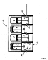
- FIG. 1 a known internal combustion engine 2 is shown.
- This internal combustion engine comprises a crankshaft 4, four pistons 6, four cylinders 8 and a combustion piston engine housing 10.
- the crankshaft 4 is supported at five bearings 12 .
- the crankshaft 4 exits at a first end face 14 and at a second end face 16 of the combustion piston engine housing 10 .
- crankshaft 4 in a rotational movement.
- the mechanical power of the internal combustion piston engine characterized in particular by a rotational speed and a torque of the crankshaft 4, can be transmitted by the crankshaft 4 to external systems.
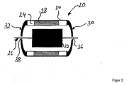
- FIG. 2 schematically a known electrical generator 20 is shown. It is known from the prior art that such a generator 20 can be coupled to the internal combustion piston engine 2 via a clutch and / or a transmission.
- the electric generator 20 has a rotor 22 and a stator 24 .
- the rotor 22 and the stator 24 are in electromagnetic interaction with each other. If the rotor is rotationally driven by the rotor shaft 26 from the outside, then the rotor 22 induces an electrical voltage in the stator coils 28.
- the stator has a stator housing 34 .
- the walls of the first end face 30 and the second end face 32 of the stator 24 are encompassed by the stator housing 30 and / or formed by the latter.
- the rotor 60 or the rotor shaft 26 is connected through the first bearing 36 to the first end face 36 of the stator housing 34 and to a first bearing 36 second bearing 38 mounted on the second end face 32 of the stator 34 .
- the combined heat and power plant 40 includes a combustion piston engine 42 and an electric generator 44 .
- the internal combustion piston engine 42 comprises a crankshaft 46, for example four pistons 48 and correspondingly four cylinders 50 .
- the internal combustion piston engine 42 further includes a combustion piston engine housing 52 and, in particular, five bearings 54 that support the crankshaft 56 on the combustion piston engine housing 52 .
- the bearings of storage are in particular characterized in that they transmit substantially no torques on the internal combustion piston engine housing 52 in the axial direction of the crankshaft 46 . The bearings therefore have at least one degree of freedom.
- the crankshaft emerges and / or projects with respect to the combustion piston engine housing.
- the crankshaft protrudes, in particular, so far that the rotor 60 and / or the rotor shaft of the electric generator 44 is secured against rotation on the crankshaft.
- the rotor 60 is therefore fastened in a rotationally fixed manner, in particular, to a first end of the shaft 52 projecting outwardly from the first end face 56 of the combustion piston engine housing 52 .
- the rotor 60 is cantilevered or cantilevered.
- the orientation of the rotor 60 is coaxial with the projecting shaft end of the crankshaft 46.
- the unit is as compact as possible, the rotor is spaced apart by a narrow gap 62, in particular the air gap, in particular of at most 2 cm, preferably of at most 5 mm, from the first end face 56 of the reciprocating internal combustion engine housing 52 60, so that preferably the smallest possible moment, in particular bending or tilting moment, acts by the rotor 60 on the bearings 54 .
- FIG. 3 illustrated that the internal combustion piston engine 42 and the electric generator 44 have a common shaft.
- the shaft forms both the crankshaft 54 of the internal combustion piston engine 42 and the rotor shaft 68 of the electric generator 44 and the rotor 60.
- the rotor shaft 68 and the crankshaft 46 are thus not separated by an additional component such as a clutch. And only in this way is it possible for the rotor 60 to be spaced apart from the first end wall 56 of the combustion piston engine housing 52 by the gap 62, which is preferably only 5 to 20 mm wide.
- This advantage is particularly enhanced by the fact that the stator housing 70 is flanged to the combustion piston engine housing 52 , wherein the stator housing 70 is in particular a partial element of the stator 72 .
- the positioning of the stator 72 to the combustion piston engine housing 52 by means of dowel pins and in particular by means of a frictional connection.
- connection elements of the generator 44 can not be cut by an axis which is axially spaced apart from each other formed on the outer periphery of the rotor points are formed, and the axis extends parallel to the axis of rotation of the rotor.
- the flange elements are preferably designed in such a way that a projection of the rotor cross-sectional area coaxial with the rotor axis on the end face of the combustion piston engine housing does not intersect the flange elements.
- the flange elements in particular do not point into the interior of the stator.
- the flange elements are designed with respect to the rest of the stator in such a way that they do not influence the axial length of the stator, or do not extend.
- FIG. 4 An alternative embodiment of the cogeneration unit is in FIG. 4 shown.
- the combustion piston engine housing 52 also forms the stator housing 70 .
- the stator housing 70 and the combustion piston engine housing 52 are thus connected to each other without interruption. They can be a common element, in particular cast element. Furthermore, it is also possible that they are welded together.
- the generator housing 70 and the combustion piston engine housing by a press fit or by a press fit non-positively and / or positively connected to each other.
- FIG. 4 a short runner and stator. Because for a compact unit, it is preferred that the rotor and / or the stator is short and in particular has a maximum axial length 66 of 15, 12.5, 10, 7.5, 5, 4 or 3 cm. It is further preferred that a ratio of a maximum radial diameter 64 to a maximum axial length 66 of the rotor or the stator is greater than 4, in particular from a range of 4 to 10, preferably from a range of 5 to 8.
- the wall of the first end face 56 of the combustion piston engine housing 52 also forms an end wall of the stator 72 .
- the unit is characterized in particular by the fact that the stator does not have its own frontal wall and that the stator housing 70 is either formed by the Verbumblekolbenmotorgephaseuse 52 or flanged to this. It therefore also eliminates the need for a separate and / or separate frontal wall for the stator 70.
- the frontal wall 56 of the internal combustion engine housing and the only partition are advantageous in FIG. 3 and in FIG. 4 illustrated that the wall of the first end face 56 of the combustion piston engine housing 52 also forms an end wall of the stator 72 .
- the rotor 60 is mounted on one side or on the fly, act by the rotor 60 and no bearing forces on the stator. Because the bearing of the rotor is also the bearing of the crankshaft 46 of the internal combustion piston engine 42, which has in particular a plurality of storage locations 54 .
- FIG. 3 and in FIG. 4 Furthermore, in particular a plurality of engine cooling lines 76 and generator cooling lines 78 are shown.
- the engine cooling conduits are preferably arranged in close proximity to the cylinders 50 .
- the generator cooling lines are arranged on the radially outer circumference of the stator. It applies to both cooling lines that they preferably form turns around a cylinder or in the radially outer area of the stator.
- the cooling lines can form a cooling circuit of cooling, which cools both the internal combustion piston engine 42 and the generator 44, or the stator 72 , wherein the cooling circuit is preferably flowed through by a fluid or in particular by water, oil or air.
- the generator is brushless and / or can also be operated as a motor. If the generator can also be operated as a motor, this can also be used in engine operation for starting the internal combustion piston engine.
- the cogeneration unit 40 has no separate flywheel element, in particular no separate flywheel. This is particularly advantageous because no space is claimed by a flywheel, so that the combined heat and power unit can be very compact.
- no separate flywheel element in particular no flywheel, is fastened to the shaft 46 or 68 in the generator-side region A leading away from the internal combustion engine 42 .
- the rotor 60 may be configured as a flywheel element of the internal combustion piston engine 42 . If the internal combustion piston engine 42 still need a separate flywheel element, as well as in the FIG. 4 shown, on the shaft 46 in the direction away from the internal combustion piston engine, non-generator side region B alternatively or additionally a, in particular separate, flywheel element, preferably a flywheel, be attached.
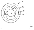
- FIG. 5 a highly simplified, schematic cross-section of the electric generator 44 is shown.
- the outer ring in FIG. 5 represents the stator housing 70 into which a stator ring 80 is inserted.
- the stator ring 80 and the stator housing 70 form a press fit, in particular a press fit.
- the inner diameter of the stator housing 70 is therefore slightly smaller than the outer diameter of the stator ring 80.
- an inner circumferential surface of the Stator housing 70 and correspondingly the outer surface of the stator ring 80 is cylindrical or conical, so that a contact surface 82 between the stator ring 80 and the stator housing 70 is substantially cylindrical or conical.
- stator ring 80 and the stator housing 70 may have guide elements to permit absolute positioning of the elements in the direction of rotation about a longitudinal axis of the stator, in particular also during insertion of the stator ring 80 .
- a feather key is suitable.
- stator teeth 84 of the stator ring 80 are shown, which are oriented inwardly, in particular in the direction of the generator shaft 68 .
- a different number of teeth 84 may be provided and / or the teeth 84 may have a different shape. It is known from the prior art that the windings of the stator coils lead around these teeth 84 .
- sixteen electromagnetic coils are arranged distributed uniformly over the circumference of the stator.
- FIG. 6 shows a section of a further preferred embodiment of the blooknningkraftwerks invention.
- a combustion piston engine 42 - here simplified and only partially reproduced - and an electric generator 44 .
- the combustion piston engine 42 includes a crankshaft 46, pistons 48, and cylinders 50.
- the combustion piston engine 42 further includes a combustion piston engine housing 52 and bearings 54 that support the crankshaft 46 on the combustion piston engine housing 52 .
- the crankshaft comes out and / or projects with respect to the combustion piston engine housing.
- the crankshaft protrudes in particular so far that a rotor carrier element 86 of the rotor 60 is non-rotatably attached to the crankshaft 46, or to its protruding shaft end 98 .
- the rotor support member 86 of the rotor 60 is rotatably coupled to the crankshaft 46 and / or connected.
- the rotor support member 86 is non-rotatably flanged to the crankshaft 46 .
- the rotor carrier element 86 and the crankshaft 46 can have fittingly configured flange elements 96 , which can be connected to one another, for example by means of screw connections and / or dowel pins, in a force and / or form-fitting manner.
- the rotor carrier element 86 is therefore at a first outwardly projecting from the first end face 56 of the combustion piston engine housing 52 flying shaft end in particular secured against rotation.
- the rotor support member 86 may also have spokes, wherein the spokes are configured in the manner of a propeller or fan blade.
- the rotor support member 86 may have radially outwardly extending webs, which preferably have the shape of a fan blade and are particularly preferably distributed over the circumference.
- the webs can fulfill two tasks. The webs can transmit force and / or moment transmitting.
- the webs can generate a flow of air during a rotational movement of the rotor support member 86 , in particular when the webs are in the form of fan blades and / or rotated about their longitudinal axis in such a way that they act as fan blades.
- the orientation of the rotor 60 is coaxial with the projecting shaft end 98 of the crankshaft 46. Further, the rotor 60 is configured as an external rotor. The rotor is thus arranged outside of the stator 72 . Opposite an inner rotor, like this in the Figures 3 and 4 is shown, a plurality of permanent magnets 90 may be preferably arranged at equal distances from each other over the circumference of the outer rotor 60 . An external rotor can therefore also have a higher magnetic flux density than an internal rotor. Since the power which can be output by a generator can be functionally traced back to a magnetic interaction with the permanent magnets of a rotor, an external rotor can consequently also have a higher nominal power. In other words, the external rotor generator can advantageously have a higher power density than an internal rotor generator.
- the rotor carrier element 86 has a coaxially, conically outwardly open region 100 and / or a region substantially perpendicular to the axis of rotation of the rotor 60 , so that the rotor 60 and the rotor carrier element 86 are preferably designed to engage around the stator 72 .
- the rotor 60 or the rotor carrier element 86 does not have its own shaft. The rotor 60 or the rotor carrier element 86 is thus shaftless and / or shaft-free.
- the rotor carrier element 86 is preferably fixed in a rotationally fixed manner to the crankshaft 46 , the rotor has no shaft outside the region of the attachment and / or the crankshaft 46 in the radial range of 0 to 5 mm about the axis of rotation of the rotor 60 .
- the rotor 60 permanent magnets 88 which are oriented inwardly.
- the permanent magnets 88 may be integrated into the rotor 60 so that the inner surface of the rotor 60 has a substantially cylindrical lateral surface is, and this particular sections of the permanent magnet 88 is formed.
- stator 72 and the stator housing 70 is fixedly connected to the motor housing 52 .
- stator 72 or the stator housing 70 may be fastened to the motor housing 52 in particular by means of dowel pins and / or screw connections.
- the stator 72 has a plurality of, in particular sixteen, stator coils 90 , which are oriented radially outward.
- the stator has cooling elements, preferably generator cooling lines 78 . These are arranged between the axis of rotation of the rotor 60 and the stator coils 90 . Further, the generator cooling ducts 78 are connected to the cooling, in particular to the cooling ducts 76, of the internal combustion piston engine 42 through a pipe connecting duct 92 .
- the voltage induced in the stator coils 90 during operation of the combined heat and power unit can be transmitted by means of electrical connection lines 94 to further electrical components.
- the combined heat and power plant may have a cover 102 .
- the cover 102 includes the electric generator 44 and terminates with the combustion piston engine housing 52 .
Landscapes
- Engineering & Computer Science (AREA)
- Chemical & Material Sciences (AREA)
- Combustion & Propulsion (AREA)
- Mechanical Engineering (AREA)
- General Engineering & Computer Science (AREA)
- Power Engineering (AREA)
- Physics & Mathematics (AREA)
- Thermal Sciences (AREA)
- Connection Of Motors, Electrical Generators, Mechanical Devices, And The Like (AREA)
Applications Claiming Priority (1)
| Application Number | Priority Date | Filing Date | Title |
|---|---|---|---|
| DE102009011477A DE102009011477A1 (de) | 2009-03-06 | 2009-03-06 | Blockheizkraftwerk-Aggregat mit einem Verbrennungskolbenmotor und einer elektrischen Maschine |
Publications (3)
| Publication Number | Publication Date |
|---|---|
| EP2226920A2 true EP2226920A2 (fr) | 2010-09-08 |
| EP2226920A3 EP2226920A3 (fr) | 2012-04-04 |
| EP2226920B1 EP2226920B1 (fr) | 2021-02-17 |
Family
ID=42045376
Family Applications (1)
| Application Number | Title | Priority Date | Filing Date |
|---|---|---|---|
| EP10002346.4A Active EP2226920B1 (fr) | 2009-03-06 | 2010-03-08 | Système de cogénération avec un moteur à combustion à piston et une machine électrique |
Country Status (4)
| Country | Link |
|---|---|
| US (1) | US20100244444A1 (fr) |
| EP (1) | EP2226920B1 (fr) |
| DE (1) | DE102009011477A1 (fr) |
| DK (1) | DK2226920T3 (fr) |
Cited By (1)
| Publication number | Priority date | Publication date | Assignee | Title |
|---|---|---|---|---|
| EP2649312A4 (fr) * | 2010-12-10 | 2014-12-10 | Viking Heat Engines As | Dispositif et procédé d'alimentation d'un système de station d'énergie thermique pour un bâtiment ou un bateau |
Families Citing this family (4)
| Publication number | Priority date | Publication date | Assignee | Title |
|---|---|---|---|---|
| FR3091338B1 (fr) * | 2018-12-28 | 2021-04-23 | Thales Sa | Dispositif de refroidissement à cycle Stirling inversé avec support monobloc |
| FR3091339B1 (fr) * | 2018-12-28 | 2021-01-01 | Thales Sa | Dispositif de refroidissement à cycle Stirling avec moteur à rotor externe |
| CN110513189A (zh) * | 2019-09-26 | 2019-11-29 | 山东理工大学 | 一种无飞轮直列四缸约束活塞发电机 |
| US20250239912A1 (en) * | 2024-01-19 | 2025-07-24 | Enginuity Power Systems, Inc. | Methods and devices for integrating generators in an engine |
Family Cites Families (16)
| Publication number | Priority date | Publication date | Assignee | Title |
|---|---|---|---|---|
| US1505702A (en) * | 1921-02-05 | 1924-08-19 | Alvin L Curtis | Portable lighting plant |
| GB191774A (en) * | 1921-08-19 | 1923-01-19 | Gen Electric Co Ltd | Improvements in internal combustion engines |
| DE1927993A1 (de) * | 1969-05-31 | 1970-12-03 | Licentia Gmbh | Motorgetriebene Lichtmaschine,insbesondere Drehstromlichtmaschine fuer Kraftfahrzeuge |
| DE3130640A1 (de) * | 1981-07-30 | 1983-02-17 | Siemens AG, 1000 Berlin und 8000 München | Elektrische maschine |
| DE8334714U1 (de) * | 1983-12-03 | 1984-05-03 | Wirges, Gerhard, 2000 Hamburg | Stromerzeuger |
| US4620521A (en) * | 1984-07-18 | 1986-11-04 | Colt Industries Operating Corp. | Modular, programmable high energy ignition system |
| AU7315394A (en) * | 1993-07-15 | 1995-02-13 | Onan Corporation | Auxiliary power system for hybrid electric vehicle |
| DE19655301B4 (de) * | 1996-05-10 | 2006-12-28 | Zf Sachs Ag | Antriebsanordnung für ein Kraftfahrzeug |
| WO1999062167A1 (fr) * | 1998-05-26 | 1999-12-02 | Yanmar Diesel Engine Co., Ltd. | Generateur de moteur |
| DE10010248A1 (de) * | 2000-03-02 | 2001-09-13 | Hatz Motoren | Stromerzeuger als Einheit aus Antriebsmotor und Generator |
| JP2002238214A (ja) * | 2001-02-13 | 2002-08-23 | Yanmar Diesel Engine Co Ltd | エンジン発電機 |
| WO2005036721A2 (fr) * | 2003-10-06 | 2005-04-21 | Edward Woods | Systemes et procedes de generation de puissance |
| DE102005047653B4 (de) * | 2005-10-05 | 2021-08-19 | Volkswagen Ag | Hybridantriebseinheit mit Niedertemperatur-Kreislauf |
| FR2898082B1 (fr) * | 2006-03-02 | 2009-12-11 | Peugeot Citroen Automobiles Sa | Agencement d'une machine electrique tournante dans un moteur a combustion interne et vehicule automobile comportant un tel agencement d'un moteur thermique et d'une machine electrique. |
| CN100452616C (zh) * | 2006-12-07 | 2009-01-14 | 无锡开普动力有限公司 | 一种多极内转子式永磁发电机的定子 |
| AT10549U1 (de) * | 2007-06-06 | 2009-05-15 | Steyr Motors Gmbh | Aus einer verbrennungskraftmaschine und einem generator bestehendes stromerzeugungsaggregat |
-
2009
- 2009-03-06 DE DE102009011477A patent/DE102009011477A1/de not_active Ceased
-
2010
- 2010-03-05 US US12/718,036 patent/US20100244444A1/en not_active Abandoned
- 2010-03-08 EP EP10002346.4A patent/EP2226920B1/fr active Active
- 2010-03-08 DK DK10002346.4T patent/DK2226920T3/da active
Non-Patent Citations (1)
| Title |
|---|
| None |
Cited By (1)
| Publication number | Priority date | Publication date | Assignee | Title |
|---|---|---|---|---|
| EP2649312A4 (fr) * | 2010-12-10 | 2014-12-10 | Viking Heat Engines As | Dispositif et procédé d'alimentation d'un système de station d'énergie thermique pour un bâtiment ou un bateau |
Also Published As
| Publication number | Publication date |
|---|---|
| EP2226920A3 (fr) | 2012-04-04 |
| DK2226920T3 (da) | 2021-04-19 |
| DE102009011477A1 (de) | 2010-09-09 |
| US20100244444A1 (en) | 2010-09-30 |
| EP2226920B1 (fr) | 2021-02-17 |
Similar Documents
| Publication | Publication Date | Title |
|---|---|---|
| DE102005060180A1 (de) | Elektrische Maschinen und Anordnungen mit einem jochlosen Stator mit modularen Blechstapeln | |
| DE19636591A1 (de) | Generator für getriebelose Windenergiekonverter | |
| WO2013045199A2 (fr) | Système d'entraînement pour éolienne | |
| EP2413483A1 (fr) | Moteur électrique pour aéronef | |
| DE112008002978T5 (de) | Elektromotor und Antriebsvorrichtung | |
| DE102014224476A1 (de) | Elektrische Antriebseinheit, Hybridantriebseinrichtung und Fahrzeug | |
| EP2933902A1 (fr) | Dissipation de la chaleur d'une machine électrique | |
| EP2379879B1 (fr) | Ensemble génératrice pour éolienne | |
| EP2226920B1 (fr) | Système de cogénération avec un moteur à combustion à piston et une machine électrique | |
| EP3326272B1 (fr) | Machine électrique | |
| EP1977499A1 (fr) | Moteur à réaction avec support magnétique actif | |
| DE102021101408A1 (de) | Elektrische maschine, antriebssystem und dessen verwendung | |
| WO2018059929A1 (fr) | Système de refroidissement | |
| DE102015215897A1 (de) | Kupplungseinrichtung für Hybridantrieb | |
| DE112006003223T5 (de) | Elektrische Maschine mit flüssigkeitsgekühltem Rotor | |
| EP3308449B1 (fr) | Anneau de stator pour générateur électrique et générateur et éolienne équipé de celui-ci | |
| EP4256199B1 (fr) | Agencement d'engrenage et de générateur comprenant un frein pour éolienne | |
| EP3107192B1 (fr) | Pompe à vide | |
| DE102011118815A1 (de) | Stromerzeugungsaggregat | |
| EP2273651A1 (fr) | Machine électrique | |
| WO2020094515A1 (fr) | Machine électrique munie d'un dispositif de refroidissement par fluide | |
| DE19923315A1 (de) | Antriebssystem für ein Kraftfahrzeug | |
| DE10110903A1 (de) | Elektrische Maschine | |
| EP0548733B1 (fr) | Moteur électrique propre à être utilisé en immersion | |
| DE102009018194A1 (de) | Windenergieanlagenantriebsstrang, Windenergieanlagenmaschinenhaus, Windenergieanlage und Windenergieanlagenpark sowie Standardcontainer |
Legal Events
| Date | Code | Title | Description |
|---|---|---|---|
| PUAI | Public reference made under article 153(3) epc to a published international application that has entered the european phase |
Free format text: ORIGINAL CODE: 0009012 |
|
| AK | Designated contracting states |
Kind code of ref document: A2 Designated state(s): AT BE BG CH CY CZ DE DK EE ES FI FR GB GR HR HU IE IS IT LI LT LU LV MC MK MT NL NO PL PT RO SE SI SK SM TR |
|
| AX | Request for extension of the european patent |
Extension state: AL BA ME RS |
|
| PUAL | Search report despatched |
Free format text: ORIGINAL CODE: 0009013 |
|
| AK | Designated contracting states |
Kind code of ref document: A3 Designated state(s): AT BE BG CH CY CZ DE DK EE ES FI FR GB GR HR HU IE IS IT LI LT LU LV MC MK MT NL NO PL PT RO SE SI SK SM TR |
|
| AX | Request for extension of the european patent |
Extension state: AL BA ME RS |
|
| RIC1 | Information provided on ipc code assigned before grant |
Ipc: F02B 63/04 20060101ALI20120227BHEP Ipc: H02K 7/18 20060101AFI20120227BHEP |
|
| 17P | Request for examination filed |
Effective date: 20120926 |
|
| 17Q | First examination report despatched |
Effective date: 20130409 |
|
| STAA | Information on the status of an ep patent application or granted ep patent |
Free format text: STATUS: EXAMINATION IS IN PROGRESS |
|
| RIC1 | Information provided on ipc code assigned before grant |
Ipc: H02K 5/16 20060101ALN20190620BHEP Ipc: H02K 9/19 20060101ALN20190620BHEP Ipc: H02K 7/18 20060101AFI20190620BHEP Ipc: H02K 1/18 20060101ALN20190620BHEP Ipc: F02B 63/04 20060101ALI20190620BHEP |
|
| GRAP | Despatch of communication of intention to grant a patent |
Free format text: ORIGINAL CODE: EPIDOSNIGR1 |
|
| STAA | Information on the status of an ep patent application or granted ep patent |
Free format text: STATUS: GRANT OF PATENT IS INTENDED |
|
| RIC1 | Information provided on ipc code assigned before grant |
Ipc: H02K 9/19 20060101ALN20200731BHEP Ipc: F02B 63/04 20060101ALI20200731BHEP Ipc: H02K 7/18 20060101AFI20200731BHEP Ipc: H02K 5/16 20060101ALN20200731BHEP Ipc: H02K 1/18 20060101ALN20200731BHEP |
|
| RIC1 | Information provided on ipc code assigned before grant |
Ipc: H02K 9/19 20060101ALN20200811BHEP Ipc: F02B 63/04 20060101ALI20200811BHEP Ipc: H02K 7/18 20060101AFI20200811BHEP Ipc: H02K 1/18 20060101ALN20200811BHEP Ipc: H02K 5/16 20060101ALN20200811BHEP |
|
| INTG | Intention to grant announced |
Effective date: 20200901 |
|
| GRAS | Grant fee paid |
Free format text: ORIGINAL CODE: EPIDOSNIGR3 |
|
| GRAA | (expected) grant |
Free format text: ORIGINAL CODE: 0009210 |
|
| STAA | Information on the status of an ep patent application or granted ep patent |
Free format text: STATUS: THE PATENT HAS BEEN GRANTED |
|
| AK | Designated contracting states |
Kind code of ref document: B1 Designated state(s): AT BE BG CH CY CZ DE DK EE ES FI FR GB GR HR HU IE IS IT LI LT LU LV MC MK MT NL NO PL PT RO SE SI SK SM TR |
|
| REG | Reference to a national code |
Ref country code: GB Ref legal event code: FG4D Free format text: NOT ENGLISH |
|
| REG | Reference to a national code |
Ref country code: CH Ref legal event code: EP |
|
| REG | Reference to a national code |
Ref country code: DE Ref legal event code: R096 Ref document number: 502010016850 Country of ref document: DE |
|
| REG | Reference to a national code |
Ref country code: AT Ref legal event code: REF Ref document number: 1362787 Country of ref document: AT Kind code of ref document: T Effective date: 20210315 Ref country code: CH Ref legal event code: NV Representative=s name: E. BLUM AND CO. AG PATENT- UND MARKENANWAELTE V, CH |
|
| REG | Reference to a national code |
Ref country code: IE Ref legal event code: FG4D Free format text: LANGUAGE OF EP DOCUMENT: GERMAN |
|
| REG | Reference to a national code |
Ref country code: FI Ref legal event code: FGE |
|
| REG | Reference to a national code |
Ref country code: DK Ref legal event code: T3 Effective date: 20210414 |
|
| REG | Reference to a national code |
Ref country code: SE Ref legal event code: TRGR |
|
| REG | Reference to a national code |
Ref country code: NO Ref legal event code: T2 Effective date: 20210217 |
|
| REG | Reference to a national code |
Ref country code: LT Ref legal event code: MG9D |
|
| REG | Reference to a national code |
Ref country code: NL Ref legal event code: MP Effective date: 20210217 |
|
| PG25 | Lapsed in a contracting state [announced via postgrant information from national office to epo] |
Ref country code: HR Free format text: LAPSE BECAUSE OF FAILURE TO SUBMIT A TRANSLATION OF THE DESCRIPTION OR TO PAY THE FEE WITHIN THE PRESCRIBED TIME-LIMIT Effective date: 20210217 Ref country code: GR Free format text: LAPSE BECAUSE OF FAILURE TO SUBMIT A TRANSLATION OF THE DESCRIPTION OR TO PAY THE FEE WITHIN THE PRESCRIBED TIME-LIMIT Effective date: 20210518 Ref country code: LT Free format text: LAPSE BECAUSE OF FAILURE TO SUBMIT A TRANSLATION OF THE DESCRIPTION OR TO PAY THE FEE WITHIN THE PRESCRIBED TIME-LIMIT Effective date: 20210217 Ref country code: BG Free format text: LAPSE BECAUSE OF FAILURE TO SUBMIT A TRANSLATION OF THE DESCRIPTION OR TO PAY THE FEE WITHIN THE PRESCRIBED TIME-LIMIT Effective date: 20210517 Ref country code: PT Free format text: LAPSE BECAUSE OF FAILURE TO SUBMIT A TRANSLATION OF THE DESCRIPTION OR TO PAY THE FEE WITHIN THE PRESCRIBED TIME-LIMIT Effective date: 20210617 |
|
| PG25 | Lapsed in a contracting state [announced via postgrant information from national office to epo] |
Ref country code: PL Free format text: LAPSE BECAUSE OF FAILURE TO SUBMIT A TRANSLATION OF THE DESCRIPTION OR TO PAY THE FEE WITHIN THE PRESCRIBED TIME-LIMIT Effective date: 20210217 Ref country code: LV Free format text: LAPSE BECAUSE OF FAILURE TO SUBMIT A TRANSLATION OF THE DESCRIPTION OR TO PAY THE FEE WITHIN THE PRESCRIBED TIME-LIMIT Effective date: 20210217 Ref country code: NL Free format text: LAPSE BECAUSE OF FAILURE TO SUBMIT A TRANSLATION OF THE DESCRIPTION OR TO PAY THE FEE WITHIN THE PRESCRIBED TIME-LIMIT Effective date: 20210217 |
|
| PG25 | Lapsed in a contracting state [announced via postgrant information from national office to epo] |
Ref country code: IS Free format text: LAPSE BECAUSE OF FAILURE TO SUBMIT A TRANSLATION OF THE DESCRIPTION OR TO PAY THE FEE WITHIN THE PRESCRIBED TIME-LIMIT Effective date: 20210617 |
|
| PG25 | Lapsed in a contracting state [announced via postgrant information from national office to epo] |
Ref country code: SM Free format text: LAPSE BECAUSE OF FAILURE TO SUBMIT A TRANSLATION OF THE DESCRIPTION OR TO PAY THE FEE WITHIN THE PRESCRIBED TIME-LIMIT Effective date: 20210217 Ref country code: EE Free format text: LAPSE BECAUSE OF FAILURE TO SUBMIT A TRANSLATION OF THE DESCRIPTION OR TO PAY THE FEE WITHIN THE PRESCRIBED TIME-LIMIT Effective date: 20210217 Ref country code: CZ Free format text: LAPSE BECAUSE OF FAILURE TO SUBMIT A TRANSLATION OF THE DESCRIPTION OR TO PAY THE FEE WITHIN THE PRESCRIBED TIME-LIMIT Effective date: 20210217 |
|
| REG | Reference to a national code |
Ref country code: DE Ref legal event code: R097 Ref document number: 502010016850 Country of ref document: DE |
|
| PG25 | Lapsed in a contracting state [announced via postgrant information from national office to epo] |
Ref country code: RO Free format text: LAPSE BECAUSE OF FAILURE TO SUBMIT A TRANSLATION OF THE DESCRIPTION OR TO PAY THE FEE WITHIN THE PRESCRIBED TIME-LIMIT Effective date: 20210217 Ref country code: ES Free format text: LAPSE BECAUSE OF FAILURE TO SUBMIT A TRANSLATION OF THE DESCRIPTION OR TO PAY THE FEE WITHIN THE PRESCRIBED TIME-LIMIT Effective date: 20210217 Ref country code: SK Free format text: LAPSE BECAUSE OF FAILURE TO SUBMIT A TRANSLATION OF THE DESCRIPTION OR TO PAY THE FEE WITHIN THE PRESCRIBED TIME-LIMIT Effective date: 20210217 Ref country code: MC Free format text: LAPSE BECAUSE OF FAILURE TO SUBMIT A TRANSLATION OF THE DESCRIPTION OR TO PAY THE FEE WITHIN THE PRESCRIBED TIME-LIMIT Effective date: 20210217 |
|
| REG | Reference to a national code |
Ref country code: BE Ref legal event code: MM Effective date: 20210331 |
|
| RAP2 | Party data changed (patent owner data changed or rights of a patent transferred) |
Owner name: LICHTBLICK SE |
|
| PLBE | No opposition filed within time limit |
Free format text: ORIGINAL CODE: 0009261 |
|
| STAA | Information on the status of an ep patent application or granted ep patent |
Free format text: STATUS: NO OPPOSITION FILED WITHIN TIME LIMIT |
|
| REG | Reference to a national code |
Ref country code: DE Ref legal event code: R081 Ref document number: 502010016850 Country of ref document: DE Owner name: LICHTBLICK SE, DE Free format text: FORMER OWNER: LICHTBLICK ZUHAUSEKRAFTWERK GMBH, 20359 HAMBURG, DE |
|
| 26N | No opposition filed |
Effective date: 20211118 |
|
| GBPC | Gb: european patent ceased through non-payment of renewal fee |
Effective date: 20210517 |
|
| PG25 | Lapsed in a contracting state [announced via postgrant information from national office to epo] |
Ref country code: IE Free format text: LAPSE BECAUSE OF NON-PAYMENT OF DUE FEES Effective date: 20210308 Ref country code: FR Free format text: LAPSE BECAUSE OF NON-PAYMENT OF DUE FEES Effective date: 20210417 Ref country code: LU Free format text: LAPSE BECAUSE OF NON-PAYMENT OF DUE FEES Effective date: 20210308 |
|
| PG25 | Lapsed in a contracting state [announced via postgrant information from national office to epo] |
Ref country code: SI Free format text: LAPSE BECAUSE OF FAILURE TO SUBMIT A TRANSLATION OF THE DESCRIPTION OR TO PAY THE FEE WITHIN THE PRESCRIBED TIME-LIMIT Effective date: 20210217 |
|
| REG | Reference to a national code |
Ref country code: AT Ref legal event code: PC Ref document number: 1362787 Country of ref document: AT Kind code of ref document: T Owner name: LICHTBLICK SE, DE Effective date: 20220127 |
|
| PG25 | Lapsed in a contracting state [announced via postgrant information from national office to epo] |
Ref country code: IT Free format text: LAPSE BECAUSE OF FAILURE TO SUBMIT A TRANSLATION OF THE DESCRIPTION OR TO PAY THE FEE WITHIN THE PRESCRIBED TIME-LIMIT Effective date: 20210217 Ref country code: GB Free format text: LAPSE BECAUSE OF NON-PAYMENT OF DUE FEES Effective date: 20210517 |
|
| PG25 | Lapsed in a contracting state [announced via postgrant information from national office to epo] |
Ref country code: IS Free format text: LAPSE BECAUSE OF FAILURE TO SUBMIT A TRANSLATION OF THE DESCRIPTION OR TO PAY THE FEE WITHIN THE PRESCRIBED TIME-LIMIT Effective date: 20210617 |
|
| PG25 | Lapsed in a contracting state [announced via postgrant information from national office to epo] |
Ref country code: BE Free format text: LAPSE BECAUSE OF NON-PAYMENT OF DUE FEES Effective date: 20210331 |
|
| REG | Reference to a national code |
Ref country code: NO Ref legal event code: CREP Representative=s name: ZACCO NORWAY AS, POSTBOKS 488, 0213 OSLO, NORGE Ref country code: NO Ref legal event code: CHAD Owner name: LICHTBLICK SE, DE |
|
| PG25 | Lapsed in a contracting state [announced via postgrant information from national office to epo] |
Ref country code: HU Free format text: LAPSE BECAUSE OF FAILURE TO SUBMIT A TRANSLATION OF THE DESCRIPTION OR TO PAY THE FEE WITHIN THE PRESCRIBED TIME-LIMIT; INVALID AB INITIO Effective date: 20100308 Ref country code: CY Free format text: LAPSE BECAUSE OF FAILURE TO SUBMIT A TRANSLATION OF THE DESCRIPTION OR TO PAY THE FEE WITHIN THE PRESCRIBED TIME-LIMIT Effective date: 20210217 |
|
| PG25 | Lapsed in a contracting state [announced via postgrant information from national office to epo] |
Ref country code: MK Free format text: LAPSE BECAUSE OF FAILURE TO SUBMIT A TRANSLATION OF THE DESCRIPTION OR TO PAY THE FEE WITHIN THE PRESCRIBED TIME-LIMIT Effective date: 20210217 |
|
| PG25 | Lapsed in a contracting state [announced via postgrant information from national office to epo] |
Ref country code: TR Free format text: LAPSE BECAUSE OF FAILURE TO SUBMIT A TRANSLATION OF THE DESCRIPTION OR TO PAY THE FEE WITHIN THE PRESCRIBED TIME-LIMIT Effective date: 20210217 |
|
| PG25 | Lapsed in a contracting state [announced via postgrant information from national office to epo] |
Ref country code: MT Free format text: LAPSE BECAUSE OF FAILURE TO SUBMIT A TRANSLATION OF THE DESCRIPTION OR TO PAY THE FEE WITHIN THE PRESCRIBED TIME-LIMIT Effective date: 20210217 |
|
| PGFP | Annual fee paid to national office [announced via postgrant information from national office to epo] |
Ref country code: SE Payment date: 20250306 Year of fee payment: 16 |
|
| PGFP | Annual fee paid to national office [announced via postgrant information from national office to epo] |
Ref country code: DK Payment date: 20250321 Year of fee payment: 16 Ref country code: FI Payment date: 20250320 Year of fee payment: 16 |
|
| PGFP | Annual fee paid to national office [announced via postgrant information from national office to epo] |
Ref country code: NO Payment date: 20250320 Year of fee payment: 16 |
|
| PGFP | Annual fee paid to national office [announced via postgrant information from national office to epo] |
Ref country code: AT Payment date: 20250319 Year of fee payment: 16 |
|
| PGFP | Annual fee paid to national office [announced via postgrant information from national office to epo] |
Ref country code: DE Payment date: 20250409 Year of fee payment: 16 |
|
| PGFP | Annual fee paid to national office [announced via postgrant information from national office to epo] |
Ref country code: CH Payment date: 20250401 Year of fee payment: 16 |