EP2226953B1 - Optisches relaissystem und verfahren - Google Patents
Optisches relaissystem und verfahren Download PDFInfo
- Publication number
- EP2226953B1 EP2226953B1 EP08862116.4A EP08862116A EP2226953B1 EP 2226953 B1 EP2226953 B1 EP 2226953B1 EP 08862116 A EP08862116 A EP 08862116A EP 2226953 B1 EP2226953 B1 EP 2226953B1
- Authority
- EP
- European Patent Office
- Prior art keywords
- signal
- amplitude
- branch
- phase
- output
- Prior art date
- Legal status (The legal status is an assumption and is not a legal conclusion. Google has not performed a legal analysis and makes no representation as to the accuracy of the status listed.)
- Not-in-force
Links
- 230000003287 optical effect Effects 0.000 title claims description 182
- 238000000034 method Methods 0.000 title claims description 20
- 238000011069 regeneration method Methods 0.000 claims description 117
- 230000008929 regeneration Effects 0.000 claims description 114
- 238000001514 detection method Methods 0.000 claims description 94
- 239000000284 extract Substances 0.000 claims description 22
- 230000008878 coupling Effects 0.000 claims description 16
- 238000010168 coupling process Methods 0.000 claims description 16
- 238000005859 coupling reaction Methods 0.000 claims description 16
- 230000003321 amplification Effects 0.000 claims description 5
- 238000003199 nucleic acid amplification method Methods 0.000 claims description 5
- 230000001960 triggered effect Effects 0.000 claims description 4
- 230000001360 synchronised effect Effects 0.000 claims description 3
- 238000001914 filtration Methods 0.000 claims 1
- 230000005540 biological transmission Effects 0.000 description 19
- 108010076504 Protein Sorting Signals Proteins 0.000 description 16
- 230000003595 spectral effect Effects 0.000 description 8
- 230000006978 adaptation Effects 0.000 description 5
- 238000005516 engineering process Methods 0.000 description 5
- 238000010586 diagram Methods 0.000 description 4
- 230000010363 phase shift Effects 0.000 description 4
- 238000006243 chemical reaction Methods 0.000 description 2
- 238000012545 processing Methods 0.000 description 2
- 238000001228 spectrum Methods 0.000 description 2
- 102100026758 Serine/threonine-protein kinase 16 Human genes 0.000 description 1
- 101710184778 Serine/threonine-protein kinase 16 Proteins 0.000 description 1
- 230000002238 attenuated effect Effects 0.000 description 1
- 230000006399 behavior Effects 0.000 description 1
- 230000006735 deficit Effects 0.000 description 1
- 230000009977 dual effect Effects 0.000 description 1
- 230000000694 effects Effects 0.000 description 1
- 230000006872 improvement Effects 0.000 description 1
- 230000004048 modification Effects 0.000 description 1
- 238000012986 modification Methods 0.000 description 1
- 230000010355 oscillation Effects 0.000 description 1
- 230000000452 restraining effect Effects 0.000 description 1
Images







Classifications
-
- H—ELECTRICITY
- H04—ELECTRIC COMMUNICATION TECHNIQUE
- H04B—TRANSMISSION
- H04B10/00—Transmission systems employing electromagnetic waves other than radio-waves, e.g. infrared, visible or ultraviolet light, or employing corpuscular radiation, e.g. quantum communication
- H04B10/29—Repeaters
- H04B10/291—Repeaters in which processing or amplification is carried out without conversion of the main signal from optical form
- H04B10/299—Signal waveform processing, e.g. reshaping or retiming
Definitions
- the present invention relates to the field of optical communications, and more particularly to an optical relay system and an optical relay method.
- a phase modulated optical signal As compared with a pure intensity modulated signal, a phase modulated optical signal has a higher spectral efficiency and a stronger anti-channel impairment capability.
- an optical relay technology is applied for the intensity modulated signal, and if the existing optical relay technology is applied to the amplitude modulated signal, phase information of the signal will be lost, which limits the performance of the optical signal from being improved.
- an optical relay technology that is, an optical regeneration method
- the optical signal is converted to an electrical signal on a receiving end, and then the electrical signal is processed.
- the optical regeneration method is briefly described as follows.
- phase noise that is, the phase information of the phase modulated signal is converted to intensity information through differential interference and balancing receiving.
- the optical-to-electrical conversion is performed on the information borne on the former signal, the phase information is recovered to the intensity information, and then a phase modulator re-loads the phase on the optical carrier phase by using the intensity information, so as to regenerate the phase.
- the inventors find that the optical regeneration method in the prior art at least has the following problems.
- the method relates to a plurality of spectrum estimation methods, so that the implementation is complicated.
- an electrical processing speed is slow, which is not suitable for the processing of high-speed signals.
- US 6795653 B1 discloses that an apparatus for reshaping optical pulses divides an incoming optical signal into a first and a second branch.
- the signal in the second branch is converted into an electrical signal which provides information concerning the pulse power of individual pulses.
- An optical modulator is provided in the first, purely optical branch for modifying the optical signal so as to attenuate the pulses by an amount which depends on the power of the pulses, higher power pulses being attenuated more than lower power pulses. This helps maintain a constant signal to noise ratio within the system and can extend the number of optical spans of an optical signal before it requires full electrical regeneration.
- EP 1544669 A1 discloses that a device has a differential phase shift keying demodulator (14) for converting a signal carrying phase modulated information into two secondary signals carrying amplitude modulated information.
- An amplitude regeneration module (16) regenerates the secondary signals.
- a differential phase shift keying demodulator (18) converts the regenerated signals into a signal carrying the same phase modulated information.
- the present invention is directed to an optical relay system and an optical relay method, which are capable of effectively restraining a phase noise generated by an optical signal during a transmission process.
- the technical solutions are described in the following.
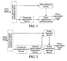
- the present invention provides an optical relay system, which includes a first optical signal distribution device, a phase detection device, an amplitude regeneration device, and a phase regeneration and load device.
- the first optical signal distribution device is adapted to receive an input signal, divide the input signal into a first branch of the input signal and a second branch of the input signal, and separately output the first branch of the input signal and the second branch of the input signal.
- the phase detection device is adapted to receive the first branch of the input signal output by the first optical signal distribution device, extract phase information of the first branch of the input signal, convert the phase information to an amplitude modulated signal, and output the amplitude modulated signal, wherein output of the amplitude regeneration device is free of phase information;.
- the amplitude regeneration device is adapted to receive the second branch of the input signal output by the first optical signal distribution device, shape the second branch of the input signal to obtain an amplitude regenerated signal, and output the amplitude regenerated signal.
- the phase regeneration and load device is adapted to receive the amplitude modulated signal output by the phase detection device and the amplitude regenerated signal output by the amplitude regeneration device, and load a phase on the amplitude regenerated signal by using the amplitude modulated signal to generate a phase regenerated signal.
- the present invention further provides an optical relay method, which includes the following steps.
- a received input signal is divided into two branchs.
- Phase information of one branch of the input signal is extracted, and the phase information is converted to an amplitude modulated signal.
- An amplitude of the other branch of the input signal is restored, so as to generate an amplitude regenerated signal, wherein the output of the amplitude regeneration device is free of phase information;
- a phase is loaded on the amplitude regenerated signal by using the amplitude modulated signal, so as to generate a phase regenerated signal.
- the amplitude modulated signal is generated according to the extracted phase information, the phase information is loaded on the phase base by using the amplitude modulated signal, so as to generate the phase regenerated signal, thus eliminating the phase noise of the signal in the transmission process, improving a transmission performance of the signal, and realizing a simple implementation method.
- phase information of an input signal is extracted, the phase information is converted to an amplitude modulated signal, and the phase information is loaded on a phase base by a phase regeneration and load device by using the amplitude modulated signal, so as to generate the phase regenerated signal is generated, thus eliminating the phase noise of the signal in a transmission process.
- an optical relay system which includes a first optical signal distribution device, a phase detection device, an amplitude regeneration device, and a phase regeneration and load device.
- the first optical signal distribution device is adapted to receive an input signal, divide the input signal into a first branch of the input signal and a second branch of the input signal, and separately output the first branch of the input signal and the second branch of the input signal.
- the phase detection device is adapted to receive the first branch of the input signal output by the first optical signal distribution device, extract phase information of the first branch of the input signal, convert the phase information to an amplitude modulated signal, and output the amplitude modulated signal.
- the amplitude modulated signal is the phase information borne on an intensity signal, and is a high-low-level signal adapted to modulate a phase of the signal.
- the amplitude regeneration device is adapted to receive the second branch of the input signal output by the first optical signal distribution device, shape the input signal to obtain an amplitude regenerated signal, and output the amplitude regenerated signal.
- the amplitude regenerated signal is a new phase base, and a phase may be loaded on the base again.
- the phase regeneration and load device is adapted to receive the amplitude modulated signal output by the phase detection device and the amplitude regenerated signal output by the amplitude regeneration device, and modulate the amplitude regenerated signal by using the amplitude modulated signal to generate a phase regenerated signal.
- the phase detection device may extract the phase information of the signal under the assistance of the signal output by the amplitude regeneration device.
- a second optical signal distribution device is placed between the amplitude regeneration device and the phase regeneration and load device, and the second optical signal distribution device is adapted to divide the amplitude regenerated signal output by the amplitude regeneration device into two branchs, output a first branch of the amplitude regenerated signal to the phase detection device, and output a second branch of the amplitude regenerated signal to the phase regeneration and load device.
- the phase detection device is further adapted to receive the first branch of the amplitude regenerated signal output by the second optical signal distribution device, and extract the phase information of the first branch of the input signal according to the first branch of the amplitude regenerated signal.
- each phase detection module is adapted to extract preset phase information of the received first branch of the input signal, convert the extracted phase information to the corresponding amplitude modulated signal, and output the corresponding amplitude modulated signal to the phase regeneration and load device.
- the phase extracted by the phase detection module 1 from the first branch of the input signal is ⁇
- the phase extracted by the phase detection module 2 from the first branch of the input signal is ⁇ /2.
- the phase detection device outputs N branchs of the amplitude modulated signals to the phase regeneration and load device.
- the optical relay system may be flexibly placed according to demands, in which the amplitude modulated signal is generated through the phase information extracted by the phase detection device, the phase information is loaded on the new phase base by the phase regeneration and load device by using the amplitude modulated signal, so as to generate the phase regenerated signal, thus eliminating the phase noise of the signal in the transmission process, improving a transmission performance of the signal, and realizing a simple implementation method.
- an optical relay system is provided in this embodiment. Being similar to Embodiment 1, the optical relay system provided in this embodiment also includes a first optical signal distribution device, a phase detection device, an amplitude regeneration device, a second optical signal distribution device (optional), and a phase regeneration and load device. Functions of the devices are the same as those of Embodiment 1, so they are not repeated here.
- the relay system is adapted for an all-optical relay of an Optical Dual Binary (ODB) signal.
- ODB Optical Dual Binary
- the phase detection device in this embodiment includes a phase detection module and a filter module.
- the phase detection module is adapted to receive a first branch of an input signal output by the first optical signal distribution device, extract phase information of the first branch of the input signal, and convert the phase information to an amplitude modulated signal, in which the amplitude modulated signal is the phase information borne on an intensity signal, and is a high-low-level signal adapted to modulate a phase of the signal.
- the filter module is adapted to receive the amplitude modulated signal output by the phase detection module, filter out a clutter signal in the amplitude modulated signal, and output the amplitude modulated signal without the clutter signal to the phase regeneration and load device.
- the second optical signal distribution device is placed between the amplitude regeneration device and the phase regeneration and load device, in which the amplitude modulated signal output by the phase detection device includes a spectral component generated by the amplitude regeneration device and a spectral component of the first branch of the input signal, and the filter module is adapted to filter the spectral component of the first branch of the input signal.
- a signal sequence of the input signal input to the first optical signal distribution device is A
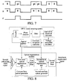
- signal sequences of the amplitude regenerated signal B output by the amplitude regeneration device and the amplitude modulated signal C output by the filter module in FIG. 5 or FIG 6 are as shown in FIG 7 , in which the signal sequence of the amplitude regenerated signal B is a recurrence of amplitude information of the input signal, a phase of the signal sequence is a non-modulated continuous phase, and the signal sequence of the amplitude modulated signal C is a recurrence of the phase information of the input signal.
- the phase detection device is adapted to convert the phase information of the signal to intensity information.
- the amplitude regeneration device needs to output the amplitude regenerated signal to perform some adaptations on the first branch of the input signal.
- the adaptation includes three aspects, namely, amplitude adaptation, frequency adaptation, and phase adaptation.
- the corresponding phase detection module particularly includes a calibration unit and a coupling unit.
- the calibration unit is adapted to receive the first branch of the input signal output by the first optical signal distribution device and one branch of the amplitude regenerated signal output by the second optical signal distribution device, calibrate an amplitude, a wavelength, and a phase of the first branch of the input signal according to the branch of the amplitude regenerated signal to generate a calibration signal having an amplitude, a frequency, and a phase that are the same as the branch of the amplitude regenerated signal, and output the calibration signal and the branch of the amplitude regenerated signal.
- the coupling unit is adapted to receive the calibration signal and the branch of the amplitude regenerated signal output by the calibration unit, interfere with the calibration signal and the branch of the amplitude regenerated signal to generate the amplitude modulated signal, and output the amplitude modulated signal.
- the filter module is adapted to receive the amplitude modulated signal output by the coupling unit, filter out the clutter signal (the spectral component of the first branch of the input signal) in the amplitude modulated signal, and output the filtered amplitude modulated signal.
- the regenerated signals After the first branch of the input signal A and the amplitude regenerated signal B input to the phase detection device pass the amplitude calibration, the wavelength calibration, and the phase calibration, the regenerated signals have the same amplitude, the same frequency, and the same phase.
- the amplitude calibration enables the two branchs signals of the first branch of the input signal A and the amplitude regenerated signal B to have the same amplitude, and the function may be implemented by a combination of an optical amplifier and an optical attenuator.
- the wavelength calibration and the phase calibration enable the two branchs signals have the same frequency by adjusting a local optical source of the amplitude regenerated signal B, and enable the phase of the amplitude regenerated signal B to be synchronous with the carrier phase of the first branch of the input signal A.
- the interference addition of the two branchs signals having the same amplitude, the same frequency, and the same phase in the coupling unit is particularly implemented in the following.
- An output sequence is the signal sequence of the amplitude modulated signal C in FIG 7 .
- the amplitude regeneration device includes a clock restoring module and an optical regeneration module.
- the clock restoring module is adapted to receive the second branch of the input signal output by the first optical signal distribution device, extract a clock signal of the second branch of the input signal, and output the clock signal.
- the optical regeneration module is adapted to receive the second branch of the input signal output by the first optical signal distribution device and the clock signal output by the clock restoring module, shape the second branch of the input signal after being triggered by the clock signal to obtain the amplitude regenerated signal, and output the amplitude regenerated signal.
- the optical regeneration module and the clock restoring module are combined, so as to form an amplitude regeneration device having an added re-timing function, so as to periodically amplify and shape the input signal.
- the clock restoring module in this embodiment adopts an optical phase lock-loop (OPLL) clock restoring system in the prior art, which particularly includes a coupler, a phase detector, a filter, an optical-to-electrical converter, a voltage controlled oscillator, an electrical-to-optical converter, and an optical splitter.
- OPLL optical phase lock-loop
- the coupler is adapted to receive the amplified second branch of the input signal and a clock control signal generated by the OPLL clock restoring system, and couple the amplified second branch of the input signal with the clock control signal.
- the phase detector is adapted to extract a clock signal in the signal coupled by the coupler.
- the filter is adapted to filter the clock signal extracted by the phase detector filter, so as to filter out the clutter signal.
- the optical-to-electrical converter is adapted to convert the filtered clock signal to an electrical signal.
- the voltage controlled oscillator is adapted to output the clock signal, in which a phase of the clock signal is controlled by a voltage in the electrical signal output by the optical-to-electrical converter.
- the electrical-to-optical converter is adapted to convert the electrical signal after an oscillation is eliminated by the voltage controlled oscillator, and serve the optical signal as the clock control signal.
- the optical splitter is adapted to divide the clock control signal converted by the electrical-to-optical converter to three branchs (with a wavelength of ⁇ c ), output a first branch of the clock control signal to the coupler, and output a second branch of the clock control signal and a third branch of the clock control signal to two level optical regeneration units of the optical regeneration module.
- the optical regeneration module particularly includes an amplifier, a first auxiliary optical generator, a first level optical regeneration unit, a first level filter, a second auxiliary optical generator, a second level optical regeneration unit, and a second level filter.
- the amplifier is adapted to receive the second branch of the input signal (with a wavelength of ⁇ s ) output by the first optical signal distribution device, amplify the second branch of the input signal, divide the second branch of the input signal into two branchs, output one branch to the coupler of the OPLL clock restoring system, and output the other branch to the first level optical regeneration unit.
- the first auxiliary optical generator is adapted to generate a first auxiliary optical signal (with a wavelength of ⁇ p 1 ).
- the first level optical regeneration unit is adapted to receive the amplified second branch of the input signal output by the amplifier, the first auxiliary optical signal, and the second branch of the clock control signal output by the optical splitter, shape the second branch of the input signal by using the first auxiliary optical signal after being triggered by the second branch of the clock control signal, obtain a first level amplitude regenerated signal (with a wavelength of ⁇ p 1 ), that is, regenerate the amplitude of the second branch of the input signal at a new wavelength position, so as to obtain the first level amplitude regenerated signal.
- the first level filter is adapted to filter out a clutter signal in the first level amplitude regenerated signal obtained by the first level optical regeneration unit, and output the filtered first level amplitude regenerated signal (with a wavelength of ⁇ s ).
- the second level optical regeneration unit is adapted to receive the first level amplitude regenerated signal filtered by the first level filter, the second auxiliary optical signal, and the third branch of the clock control signal output by the optical splitter, shape the first level amplitude regenerated signal by using the second auxiliary optical signal after being triggered by the third branch of the clock control signal, and obtain a second level amplitude regenerated signal (with a wavelength of ⁇ s ).
- the second level filter is adapted to filter out a clutter signal in the second level amplitude regenerated signal obtained by the second level optical regeneration unit, and output the amplitude regenerated signal (with a wavelength of ⁇ s ).
- the phase regeneration and load device particularly includes an amplification module, a coupling module, a phase modulation module, and a filter module.
- the amplification module is adapted to receive the amplitude modulated signal output by the phase detection device, amplify the amplitude modulated signal, and output the amplified amplitude modulated signal.
- the coupling module is adapted to receive the amplitude modulated signal output by the amplification module and the amplitude regenerated signal output by the amplitude regeneration device, couple the amplified amplitude modulated signal with the amplitude regenerated signal, and output a coupled signal.
- the phase modulation module is adapted to receive the coupled signal output by the coupling module, load the phase information on the coupled signal to generate the phase regenerated signal, and output the phase regenerated signal.
- the filter module is adapted to receive the phase regenerated signal output by the phase modulation module, filter out a clutter signal in the phase regenerated signal, and obtain the phase regenerated signal without the clutter signal.
- the phase modulation module utilizes a cross-phase modulate (that is, XPM) effect to modulate the phase on the amplitude regenerated signal by using the amplitude modulated signal, so as to re-load the complete phase information on the amplitude regenerated signal.
- a cross-phase modulate that is, XPM
- the amplitude modulated signal is generated through the phase information extracted by the phase detection device, the phase information is loaded on the new phase base by the phase regeneration and load device by using the amplitude modulated signal, so as to generate the phase regenerated signal, thus eliminating the phase noise of the signal in the transmission process, improving a transmission performance of the signal, and realizing a simple implementation method.
- an optical relay system is provided in this embodiment. Being similar to Embodiment 1, the optical relay system provided in this embodiment also includes a first optical signal distribution device, a phase detection device, an amplitude regeneration device, a second optical signal distribution device (optional), and a phase regeneration and load device. Functions of the devices are the same as that of Embodiment 1, so they are not described here.
- the relay system is adapted for an all-optical relay of a differential phase shift keying (DPSK) signal.
- DPSK differential phase shift keying
- the amplitude regeneration device of the optical relay system provided in this embodiment includes a continuous light emitting module and a phase calibration module.
- the continuous light emitting module is adapted to provide a continuous light.
- the phase calibration module is adapted to receive a second branch of an input signal output by the first optical signal distribution device and the continuous light provided by the continuous light emitting module, calibrate a phase of the continuous light according to the second branch of the input signal to obtain an amplitude regenerated signal, and output the amplitude regenerated signal.
- the continuous light emitting module is a simplified amplitude regeneration device when the signal is in the DPSK format.
- a phase of the amplitude regenerated signal is the same as a carrier of the second branch of the input signal.
- the phase detection device in this embodiment particularly includes a phase detection module and a filter module, which are not described in detail here.
- the second optical signal distribution device is placed between the amplitude regeneration device and the phase regeneration and load device, in which an amplitude modulated signal output by the phase detection device includes a spectral component generated by the amplitude regeneration device and a spectral component of the first branch of the input signal, and the filter module is adapted to filter the spectral component of the first branch of the input signal.
- Embodiment 2 This embodiment is different from Embodiment 2 that as compared with the ODB signal, the DPSK signal is borne on the phase instead of the amplitude, such that here the amplitude regeneration device only needs to perform a phase calibration on the continuous light output by the continuous light emitting module.
- the phase detection device needs a reference signal, and the reference signal may be obtained from the amplitude regenerated signal, as shown in FIG 10 , alternatively, the reference signal does not include data information, so the reference signal may also be generated in the phase detection device, as shown in FIG. 11 .
- a signal sequence of the input signal input to the first optical signal distribution device is A
- signal sequences of the amplitude regenerated signal B output by the amplitude regeneration device and the amplitude modulated signal C output by the filter module in FIG. 10 or 11 are as shown in FIG 12 , in which the signal sequence of the amplitude regenerated signal B is a recurrence of amplitude information of the input signal, a phase of the signal sequence is a non-modulated continuous phase, and the signal sequence of the amplitude modulated signal C is a recurrence of the phase information of the input signal.
- the amplitude modulated signal is generated through the phase information extracted by the phase detection device, the phase information is loaded on the new phase base by the phase regeneration and load device by using the amplitude modulated signal, so as to generate the phase regenerated signal, thus eliminating the phase noise of the signal in the transmission process, improving a transmission performance of the signal, and realizing a simple implementation method.
- an optical relay system is provided in this embodiment. Being similar to Embodiment 1, the optical relay system provided in this embodiment also includes a first optical signal distribution device, a phase detection device, an amplitude regeneration device, a second optical signal distribution device (optional), and a phase regeneration and load device. Functions of the devices are the same as those of Embodiment 1, so they are not repeated here.
- the optical relay system is adapted for an all-optical relay of a differential quadrature phase shift keying (DQPSK) signal.
- DQPSK differential quadrature phase shift keying
- the system provided in this embodiment is designed in a serial mode, that is, the phase regeneration and load device implements the loading of the phase through three phase modulators.
- the DQPSK signal has four phases, such that the phase detection device needs to provide three amplitude modulated signal, for modulating three phases.
- the phase detection device particularly includes a first power dividing module, a first phase detection module, a second power dividing module, a first determination module, an inversion module, a second determination module, a second phase detection module, and a third determination module.
- the first power dividing module is adapted to receive a first branch of an input signal output by the first optical signal distribution device, divide the first branch of the input signal into two branchs, and output the two branchs.
- the first phase detection module is adapted to receive one branch of signal of the first branch of the input signal output by the first power dividing module, extract phase information of the branch of the signal, convert the phase information to a first amplitude modulated signal, and output the first amplitude modulated signal.
- the second power dividing module is adapted to receive the first amplitude modulated signal output by the first phase detection module, divide the first amplitude modulated signal into two branchs, and output the two branchs.
- the first determination module is adapted to receive one branch of the first amplitude modulated signal output by the second power dividing module, determine whether an amplitude of the branch of the first amplitude modulated signal is a first preset amplitude, and if an amplitude of the branch of the first amplitude modulated signal is a first preset amplitude, output the branch of the first amplitude modulated signal.
- the inversion module is adapted to invert the amplitude of the branch of the first amplitude modulated signal output by the first determination module, and output the inverted first amplitude modulated signal to the phase regeneration and load device.
- the second determination module is adapted to receive the other branch of the first amplitude modulated signal output by the second power dividing module, determine whether an amplitude of the other branch of the first amplitude modulated signal is a second preset amplitude, and if an amplitude of the other branch of the first amplitude modulated signal is a second preset amplitude, output the other branch of the first amplitude modulated signal to the phase regeneration and load device.
- the second phase detection module is adapted to receive the other branch of signal of the first branch of the input signal output by the power dividing module, extract phase information of the other branch of the signal, convert the phase information to a second amplitude modulated signal, and output the second amplitude modulated signal.
- the third determination module is adapted to receive the second amplitude modulated signal output by the second phase detection module, determine whether an amplitude of the second amplitude modulated signal is a third preset amplitude, and if an amplitude of the second amplitude modulated signal is a third preset amplitude, output the second amplitude modulated signal to the phase regeneration and load device.
- the phase regeneration and load device is adapted to receive the inverted first amplitude modulated signal, the other branch of the first amplitude modulated signal, and the second amplitude modulated signal output by the phase detection device, and the amplitude regenerated signal output by the amplitude regeneration device, load the phase on the amplitude regenerated signal by using the inverted first amplitude modulated signal, the other branch of the amplitude modulated signal, and the second amplitude modulated signal, so as to generate the phase regenerated signal.
- phase regeneration and load device includes a first phase modulation module, a second phase modulation module, and a third phase modulation module.
- the first phase modulation module is adapted to receive the second amplitude modulated signal output by the third determination module and the amplitude regenerated signal output by the amplitude regeneration device, load the phase on the amplitude regenerated signal by using the second amplitude modulated signal to obtain a first phase regenerated signal, and output the first phase regenerated signal.
- the second phase modulation module is adapted to receive the first phase regenerated signal output by the first phase modulation module and the other branch of the first amplitude modulated signal output by the second determination module, load a phase on the first phase regenerated signal by using the other branch of the first amplitude modulated signal to obtain a second phase regenerated signal, and output the second phase regenerated signal.
- the third phase modulation module is adapted to receive the second phase regenerated signal output by the second phase modulation module and the inverted first amplitude modulated signal output by the inversion module, and load a phase on the second phase regenerated signal by using the inverted first amplitude modulated signal, so as to generate the phase regenerated signal.
- the amplitude regeneration device in this embodiment particularly includes a continuous light emitting module and a phase calibration module, having functions that are the same as those in Embodiment 3, such that they are not described in detail here.
- the second optical signal distribution device is placed between the amplitude regeneration device and the phase regeneration and load device, and the second optical signal distribution device is adapted to provide auxiliary signals for the first phase detection module and the second phase detection module, so as to extract the phase.
- Functions of the second optical signal distribution device are the same as those in Embodiment 1, and are not described in detail here.
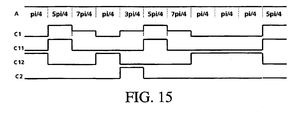
- the DQPSK signal includes 4 phases, the amplitude signal output by the first phase detection module includes 3 levels, which are a high level, a low level, and an intermediate level.
- the high or low level are respectively corresponding to one phase
- the intermediate level are corresponding to two phases.
- the first phase detection module and the second phase detection module each detect two of the four phases, and amplitudes of the signals output by the first determination module, the second determination module, and the third determination module are different.
- the amplitude of the signal output by the first determination module needs to be inverted, the amplitude 0 is inverted to 1, the amplitude 1 is inverted to 0, and in this embodiment, the phase of the signal is modulated at a position of ⁇ /4.
- the three phase modulation modules may also be combined into a phase modulator.
- the input amplitude modulated signals C1, C11, and C12 need to be adjusted, such that each branch of signal may be modulated into the corresponding optical phase.
- the optical relay system is different from an existing DQPSK modulator that an input of the existing DQPSK modulator is two-dimensional information (2-bit data information), and an output is one-dimensional information (phase information), but the optical relay system of this embodiment directly obtains the phase information of the signal, and regenerates the phase information.
- the amplitude modulated signal is generated through the phase information extracted by the phase detection device, the phase information is loaded on the new phase base by the phase regeneration and load device by using the amplitude modulated signal, so as to generate the phase regenerated signal, thus eliminating the phase noise of the signal in the transmission process, improving a transmission performance of the signal, and realizing a simple implementation method.
- an optical relay system is provided in this embodiment. Being similar to Embodiment 1, the optical relay system provided in this embodiment also includes a first optical signal distribution device, a phase detection device, an amplitude regeneration device, a second optical signal distribution device (optional), and a phase regeneration and load device. Functions of the devices are the same as those of Embodiment 1, so they are not repeated here.
- the optical relay system is adapted for an all-optical relay of a DQPSK signal.
- the system designs the phase detection device in a parallel mode, the phase detection device outputs two branchs of an amplitude modulated signal, and the phase regeneration and load device modulates an amplitude regenerated signal by using the two branchs of the amplitude modulated signal at the same time, such that the relay system is substantially a parallel system.
- the phase detection device extracts the phase information of the signal from the first branch of the input signal, and converts the phase information to the amplitude signal, and the phase is loaded on the new phase base by using the amplitude signal.
- the phase detection device extracts the phase information of the signal from a first branch of an input signal, and restores the phase information to an original two-bit data signal, and the phase information is loaded on a phase base by using the two-bit data signal.
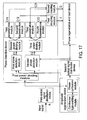
- the phase detection device of the optical relay system particularly includes a first power dividing module, a first phase detection module, a second power dividing module, a first determination module, a second determination module, a second phase detection module, a third power dividing module, a third determination module, a fourth determination module, a first coupling module, and a second coupling module.
- the first power dividing module is adapted to receive the first branch of the input signal output by the first optical signal distribution device, divide the first branch of the input signal into two branchs, and output the two branchs.
- the first phase detection module is adapted to receive one branch of signal of the first branch of the input signal output by the first power dividing module, extract phase information of the branch of the signal, convert the phase information to a first amplitude modulated signal, and output the first amplitude modulated signal, in which the first amplitude modulated signal is a data signal.
- the second power dividing module is adapted to receive the first amplitude modulated signal output by the first phase detection module, divide the first amplitude modulated signal into two branchs, and output the two branchs.
- the first determination module is adapted to receive one branch of the first amplitude modulated signal output by the second power dividing module, determine whether an amplitude of the branch of the first amplitude modulated signal is a first preset amplitude, and if an amplitude of the branch of the first amplitude modulated signal is a first preset amplitude, output the branch of the first amplitude modulated signal.
- the second determination module is adapted to receive the other branch of the first amplitude modulated signal output by the second power dividing module, determine whether an amplitude of the other branch of the first amplitude modulated signal is a second preset amplitude, and if an amplitude of the other branch of the first amplitude modulated signal is a second preset amplitude, output the other branch of the first amplitude modulated signal.
- the second phase detection module is adapted to receive the other branch of signal of the first branch of the input signal output by the power dividing module, extract phase information of the other branch of the signal, convert the phase information to a second amplitude modulated signal, and output the second amplitude modulated signal, in which the first amplitude modulated signal is also a data signal.
- the third power dividing module is adapted to receive the second amplitude modulated signal output by the second phase detection module, divide the second amplitude modulated signal into two branchs, and output the two branchs.
- the third determination module is adapted to receive one branch of the second amplitude modulated signal output by the third power dividing module, determine whether an amplitude of the branch of the second amplitude modulated signal is a third preset amplitude, and if an amplitude of the branch of the second amplitude modulated signal is a third preset amplitude, output the branch of the second amplitude modulated signal.
- the fourth determination module is adapted to receive the other branch of the second amplitude modulated signal output by the third power dividing module, determine whether an amplitude of the other branch of the second amplitude modulated signal is a fourth preset amplitude, and if an amplitude of the other branch of the second amplitude modulated signal is a fourth preset amplitude, output the other branch of the second amplitude modulated signal.
- the first coupling module is adapted to receive the other branch of the first amplitude modulated signal output by the second determination module and the other branch of the second amplitude modulated signal output by the fourth determination module, couple the other branch of the first amplitude modulated signal with the other branch of the second amplitude modulated signal to obtain a first coupled amplitude modulated signal, and output the first coupled amplitude modulated signal to the phase regeneration and load device.
- the second coupling module is adapted to receive the branch of the first amplitude modulated signal output by the first determination module and the branch of the second amplitude modulated signal output by the third determination module, couple the branch of the first amplitude modulated signal with the branch of the second amplitude modulated signal to obtain a second coupled amplitude modulated signal, and output the second coupled amplitude modulated signal to the phase regeneration and load device.
- the phase regeneration and load device is adapted to receive the first coupled amplitude modulated signal and the second coupled amplitude modulated signal output by the phase detection device, and the amplitude regenerated signal output by the amplitude regeneration device, and load the phase on the amplitude regenerated signal by using the first coupled amplitude modulated signal and the second coupled amplitude modulated signal, so as to generate the phase regenerated signal.
- a second optical signal distribution device may also be placed in the optical relay system, and other devices are the same as those in FIG 16 , and are not described in detail here.
- the amplitude modulated signal (being the two-bit data signal) is generated through the phase information extracted by the phase detection device, the phase information is loaded on the new phase base by the phase regeneration and load device by using the amplitude modulated signal, so as to generate the phase regenerated signal, thus eliminating the phase noise of the signal in the transmission process, improving a transmission performance of the signal, and realizing a simple implementation method.
- An optical relay system is provided in this embodiment.
- the optical relay system is applicable to a return to zero-DPSK signal and an RZ-DQPSK signal.
- the optical relay system provided in this embodiment may be several combinations of the system provided in the embodiments, as shown in FIGs. 19 , 20 , and 21 , the optical relay system provided in this embodiment is similar to that in Embodiment 3, Embodiment 4, and Embodiment 5, and a difference is that the amplitude regeneration device includes a clock restoring module and a phase calibration module.
- the clock restoring module is adapted to receive a second branch of an input signal output by a first optical signal distribution device, restore a clock signal of the second branch of the input signal, and output the restored clock signal.
- the phase calibration module is adapted to receive the second branch of the input signal output by the first optical signal distribution device and the clock signal output by the clock restoring module, calibrate a phase of the clock signal according to the second branch of the input signal to obtain the amplitude regenerated signal having a carrier synchronous with the second branch of the input signal, and output the amplitude regenerated signal.
- clock restoring module are the same as the clock restoring module in Embodiment 2
- phase calibration module are the same as the phase calibration module in Embodiment 3 3, so they are not described in detail.
- Particular implementation functions of other modules or devices are the same as that of the embodiments, so they are not described in detail.
- the optical relay system may complete the relay of the ODB, the DPSK, the DQPSK, and other phase modulated signals, and may also be applicable to he RZ-ODB, the RZ-DPSK, the RZ-DQPSK, and other RZ type signals.
- the amplitude of the input signal needs to be regenerated, the regenerated signal instead of the continuous light serves as the phase base of the phase modulated signal, the phase information is loaded, and phase interferences during a transmission process are eliminated.
- an optical relay method is provided in this embodiment, which includes the following steps.
- step 101 divide a received input signal into two branchs.
- step 102 extract phase information of one branch of the input signal, and convert the phase information to an amplitude modulated signal.
- the amplitude modulated signal may be implemented through the two particular modes in the following.
- the amplitude modulated signal may be filtered, so as to filter out a clutter signal in the amplitude modulated signal, in which the clutter signal may be an interference signal generated in a transmission process.
- step 103 restore amplitude of the other branch of the input signal, so as to generate an amplitude regenerated signal.
- the amplitude of the other branch of the input signal may be restored in different modes according to different types of input signals, for example, for an ODB signal, the amplitude may be regenerated on a new wavelength position of the input signal, and then the amplitude is regenerated on the former wavelength position, that is, a waveform of the ODB signal is shaped; for a DPSK signal, a phase calibration is performed on a continuous light according to a carrier of the input signal, such that the phase of the continuous light is the same as the phase of the input signal; and for an RZ-DPSK signal and an RZ-DQPSK signal, the clock of the input signal may be directly restored.
- step 104 load a phase on the amplitude regenerated signal by using the amplitude modulated signal, so as to generate a phase regenerated signal.
- a sequence of step 102 and step 103 may be exchanged without any strict limit.
- the phase information of the input signal is extracted, the phase information is converted to the amplitude modulated signal, and the phase is loaded on the phase base by using the amplitude modulated signal, so the phase noise of the signal in the transmission process is eliminated, and a transmission performance is improved.
- All or part of the content according to the embodiments of the present invention may be implemented by software programming, and the software program may be stored in a readable storage medium, for example, a hard disk, an optical disk, or a floppy disk in a computer.
Landscapes
- Physics & Mathematics (AREA)
- Electromagnetism (AREA)
- Engineering & Computer Science (AREA)
- Computer Networks & Wireless Communication (AREA)
- Signal Processing (AREA)
- Optical Communication System (AREA)
Claims (17)
- Optisches Übertragungssystem, das Folgendes umfasst:eine erste Verteilungsvorrichtung für optische Signale, die ausgelegt ist, ein Eingangssignal zu empfangen, das Eingangssignal in einen ersten Zweig des Eingangssignals und einen zweiten Zweig des Eingangssignals aufzuteilen und den ersten Zweig des Eingangssignals und den zweiten Zweig des Eingangssignals getrennt auszugeben;und das ferner Folgendes umfasst:eine Phasendetektionsvorrichtung, die ausgelegt ist, den ersten Zweig des Eingangssignals, der von der ersten Verteilungsvorrichtung für optische Signale ausgegeben wird, zu empfangen, Phaseninformationen des ersten Zweigs des Eingangssignals zu extrahieren, die Phaseninformationen in ein amplitudenmoduliertes Signal umzusetzen und das amplitudenmodulierte Signal auszugeben;eine Amplitudenregenerierungsvorrichtung, die ausgelegt ist, den zweiten Zweig des Eingangssignals, der von der ersten Verteilungsvorrichtung für optische Signale ausgegeben wird, zu empfangen, den zweiten Zweig des Eingangssignals zu formen, um ein amplitudenregeneriertes Signal zu erhalten, und das amplitudenregenerierte Signal auszugeben, wobei die Ausgabe der Amplitudenregenerierungsvorrichtung frei von Phaseninformationen ist; undeine Phasenregenerierungs- und -ladevorrichtung, die ausgelegt ist, das amplitudenmodulierte Signal, das von der Phasendetektionsvorrichtung ausgegeben wird, und das amplitudenregenerierte Signal, das von der Amplitudenregenerierungsvorrichtung ausgegeben wird, zu empfangen und unter Verwendung des amplitudenmodulierten Signals eine Phase auf das amplitudenregenerierte Signal zu laden, um ein phasenregeneriertes Signal zu erzeugen.
- Optisches Übertragungssystem nach Anspruch 1, wobei eine zweite Verteilungsvorrichtung für optische Signale zwischen der Amplitudenregenerierungsvorrichtung und der Phasenregenerierungs- und -ladevorrichtung angeordnet ist, wobei die zweite Verteilungsvorrichtung für optische Signale ausgelegt ist, das amplitudenregenerierte Signal, das von der Amplitudenregenerierungsvorrichtung ausgegeben wird, in zwei Zweige aufzuteilen, einen ersten Zweig des amplitudenregenerierten Signals zu der Phasendetektionsvorrichtung auszugeben und einen zweiten Zweig des amplitudenregenerierten Signals zu der Phasenregenerierungs- und -ladevorrichtung auszugeben;
wobei dementsprechend die Phasendetektionsvorrichtung ferner ausgelegt ist, einen ersten Zweig des amplitudenregenerierten Signals, der von der Amplitudenregenerierungsvorrichtung ausgegeben wird, zu empfangen und die Phaseninformationen des ersten Zweigs des Eingangssignals in Übereinstimmung mit dem ersten Zweig des amplitudenregenerierten Signals zu extrahieren. - Optisches Übertragungssystem nach Anspruch 1 oder 2, wobei die Phasendetektionsvorrichtung mehrere Phasendetektionsmodule umfasst, wobei jedes Phasendetektionsmodul ausgelegt ist, voreingestellte Phaseninformationen des empfangenen ersten Zweigs des Eingangssignals zu extrahieren, die extrahierten Phaseninformationen getrennt in ein entsprechendes amplitudenmoduliertes Signal umzusetzen und das entsprechende amplitudenmodulierte Signal zu der Phasenregenerierungs- und -ladevorrichtung auszugeben.
- Optisches Übertragungssystem nach Anspruch 1, wobei die Phasendetektionsvorrichtung Folgendes umfasst:ein Phasendetektionsmodul, das ausgelegt ist, den ersten Zweig des Eingangssignals, der von der ersten Verteilungsvorrichtung für optische Signale ausgegeben wird, zu empfangen, die Phaseninformationen des ersten Zweigs des Eingangssignals zu extrahieren, die Phaseninformationen in ein amplitudenmoduliertes Signal umzusetzen und das amplitudenmodulierte Signal auszugeben; undein Filtermodul, das ausgelegt ist, das amplitudenmodulierte Signal, das von dem Phasendetektionsmodul ausgegeben wird, zu empfangen, ein Störsignal in dem amplitudenmodulierten Signal auszufiltern und das amplitudenmodulierte Signal ohne das Störsignal zu der Phasenregenerierungs- und -ladevorrichtung auszugeben.
- Optisches Übertragungssystem nach Anspruch 2, wobei die Phasendetektionsvorrichtung Folgendes umfasst:ein Phasendetektionsmodul, das ausgelegt ist, den ersten Zweig des Eingangssignals, der von der ersten Verteilungsvorrichtung für optische Signale ausgegeben wird, und den ersten Zweig des amplitudenregenerierten Signals, der von der zweiten Verteilungsvorrichtung für optische Signale ausgegeben wird, zu empfangen, die Phaseninformationen des ersten Zweigs des Eingangssignals in Übereinstimmung mit dem ersten Zweig des amplitudenregenerierten Signals zu extrahieren, die Phaseninformationen in das amplitudenmodulierte Signal umzusetzen und das amplitudenmodulierte Signal auszugeben; undein Filtermodul, das ausgelegt ist, das amplitudenmodulierte Signal, das von dem Phasendetektionsmodul ausgegeben wird, zu empfangen, ein Störsignal in dem amplitudenmodulierten Signal auszufiltern und das amplitudenmodulierte Signal ohne das Störsignal zu der Phasenregenerierungs- und -ladevorrichtung auszugeben.
- Optisches Übertragungssystem nach Anspruch 5, wobei das Phasendetektionsmodul Folgendes umfasst:eine Kalibrierungseinheit, die ausgelegt ist, den ersten Zweig des Eingangssignals, der von der ersten Verteilungsvorrichtung für optische Signale ausgegeben wird, und den ersten Zweig des amplitudenregenerierten Signals, der von der zweiten Verteilungsvorrichtung für optische Signale ausgegeben wird, zu empfangen, eine Amplitude, eine Wellenlänge und eine Phase des ersten Zweigs des Eingangssignals in Übereinstimmung mit dem ersten Zweig des amplitudenregenerierten Signals zu kalibrieren, um ein Kalibrierungssignal zu erzeugen, das eine Amplitude, eine Frequenz und eine Phase aufweist, die gleich dem ersten Zweig des amplitudenregenerierten Signals sind, und das Kalibrierungssignal und den ersten Zweig des amplitudenregenerierten Signals auszugeben; undeine Kopplungseinheit, die ausgelegt ist, das Kalibrierungssignal und den ersten Zweig des amplitudenregenerierten Signals, die von der Kalibrierungseinheit ausgegeben werden, zu empfangen, das Kalibrierungssignal und den ersten Zweig des amplitudenregenerierten Signals zu überlagern, um das amplitudenmodulierte Signal zu erzeugen, und das amplitudenmodulierte Signal auszugeben.
- Optisches Übertragungssystem nach Anspruch 1 oder 2, wobei die Amplitudenregenerierungsvorrichtung Folgendes umfasst:ein Taktwiederherstellungsmodul, das ausgelegt ist, den zweiten Zweig des Eingangssignals, der von der ersten Verteilungsvorrichtung für optische Signale ausgegeben wird, zu empfangen, ein Taktsignal des zweiten Zweigs des Eingangssignals zu extrahieren und das Taktsignal auszugeben; undein optisches Regenerierungsmodul, das ausgelegt ist, den zweiten Zweig des Eingangssignals, der von der ersten Verteilungsvorrichtung für optische Signale ausgegeben wird, und das Taktsignal, das von dem Taktwiederherstellungsmodul ausgegeben wird, zu empfangen, den zweiten Zweig des Eingangssignals zu formen, nachdem es von dem Taktsignal getriggert wurde, um das amplitudenregenerierte Signal zu erhalten, und das amplitudenregenerierte Signal auszugeben.
- Optisches Übertragungssystem nach Anspruch 1 oder 2, wobei die Phasenregenerierungs- und -ladevorrichtung Folgendes umfasst:ein Verstärkungsmodul, das ausgelegt ist, das amplitudenmodulierte Signal, das von der Phasendetektionsvorrichtung ausgegeben wird, zu empfangen, das amplitudenmodulierte Signal zu verstärken und das verstärkte amplitudenmodulierte Signal auszugeben;ein Kopplungsmodul, das ausgelegt ist, das amplitudenmodulierte Signal, das von dem Verstärkungsmodul ausgegeben wird, und das amplitudenregenerierte Signal, das von der Amplitudenregenerierungsvorrichtung ausgegeben wird, zu empfangen, das verstärkte amplitudenmodulierte Signal mit dem amplitudenregenerierten Signal zu koppeln und das gekoppelte Signal auszugeben;ein Phasenmodulationsmodul, das ausgelegt ist, das gekoppelte Signal, das von dem Kopplungsmodul ausgegeben wird, zu empfangen, die Phaseninformationen auf das gekoppelte Signal zu laden, um das phasenregenerierte Signal zu erzeugen, und das phasenregenerierte Signal auszugeben; undein Filtermodul, das ausgelegt ist, das phasenregenerierte Signal, das von dem Phasenmodulationsmodul ausgegeben wird, zu empfangen und ein Störsignal in dem phasenregenerierten Signal auszufiltern, um das phasenregenerierte Signal ohne das Störsignal zu erhalten.
- Optisches Übertragungssystem nach Anspruch 1 oder 2, wobei die Amplitudenregenerierungsvorrichtung Folgendes umfasst:ein Emissionsmodul für Dauerlicht, das ausgelegt ist, Dauerlicht bereitzustellen; undein Phasenkalibrierungsmodul, das ausgelegt ist, den zweiten Zweig des Eingangssignals, der von der ersten Verteilungsvorrichtung für optische Signale ausgegeben wird, und das Dauerlicht, das von dem Emissionsmodul für Dauerlicht bereitgestellt ist, zu empfangen, eine Phase des Dauerlichts in Übereinstimmung mit dem zweiten Zweig des Eingangssignals zu kalibrieren, um das amplitudenregenerierte Signal zu erhalten, und das amplitudenregenerierte Signal auszugeben.
- Optisches Übertragungssystem nach Anspruch 1 oder 2, wobei die Phasendetektionsvorrichtung Folgendes umfasst:ein erstes Leistungsteilungsmodul, das ausgelegt ist, den ersten Zweig des Eingangssignals, der von der ersten Verteilungsvorrichtung für optische Signale ausgegeben wird, zu empfangen, den ersten Zweig des Eingangssignals in zwei Zweige aufzuteilen und die zwei Zweige auszugeben;ein erstes Phasendetektionsmodul, das ausgelegt ist, einen Zweig des ersten Zweigs des Eingangssignals, der von dem ersten Leistungsteilungsmodul ausgegeben wird, zu empfangen, Phaseninformationen des Zweigs des Signals zu extrahieren, die Phaseninformationen in ein erstes amplitudenmoduliertes Signal umzusetzen und das erste amplitudenmodulierte Signal auszugeben;ein zweites Leistungsteilungsmodul, das ausgelegt ist, das erste amplitudenmodulierte Signal, das von dem ersten Phasendetektionsmodul ausgegeben wird, zu empfangen, das erste amplitudenmodulierte Signal in zwei Zweige aufzuteilen und die zwei Zweige auszugeben;ein erstes Bestimmungsmodul, das ausgelegt ist, einen Zweig des ersten amplitudenmodulierten Signals, der von dem zweiten Leistungsteilungsmodul ausgegeben wird, zu empfangen, zu bestimmen, ob eine Amplitude des Zweigs des ersten amplitudenmodulierten Signals eine erste voreingestellte Amplitude ist, und dann, wenn eine Amplitude des Zweigs des ersten amplitudenmodulierten Signals eine erste voreingestellte Amplitude ist, den Zweig des ersten amplitudenmodulierten Signals auszugeben;ein Inversionsmodul, das ausgelegt ist, die Amplitude des Zweigs des ersten amplitudenmodulierten Signals, der von dem ersten Bestimmungsmodul ausgegeben wird, zu invertieren und das invertierte erste amplitudenmodulierte Signal zu der Phasenregenerierungs- und -ladevorrichtung auszugeben;ein zweites Bestimmungsmodul, das ausgelegt ist, den anderen Zweig des ersten amplitudenmodulierten Signals, der von dem zweiten Leistungsteilungsmodul ausgegeben wird, zu empfangen, zu bestimmen, ob eine Amplitude des anderen Zweigs des ersten amplitudenmodulierten Signals eine zweite voreingestellte Amplitude ist, und dann, wenn eine Amplitude des anderen Zweigs des ersten amplitudenmodulierten Signals eine zweite voreingestellte Amplitude ist, den anderen Zweig des ersten amplitudenmodulierten Signals zu der Phasenregenerierungs- und -ladevorrichtung auszugeben;ein zweites Phasendetektionsmodul, das ausgelegt ist, den anderen Zweig des ersten Zweigs des Eingangssignals, der von dem Leistungsteilungsmodul ausgegeben wird, zu empfangen, Phaseninformationen des anderen Zweigs des Signals zu extrahieren, die Phaseninformationen in ein zweites amplitudenmoduliertes Signal umzusetzen und das zweite amplitudenmodulierte Signal auszugeben; undein drittes Bestimmungsmodul, das ausgelegt ist, das zweite amplitudenmodulierte Signal, das von dem zweiten Phasendetektionsmodul ausgegeben wird, zu empfangen, zu bestimmen, ob eine Amplitude des zweiten amplitudenmodulierten Signals eine dritte voreingestellte Amplitude ist, und dann, wenn eine Amplitude des zweiten amplitudenmodulierten Signals eine dritte voreingestellte Amplitude ist, das zweite amplitudenmodulierte Signal zu der Phasenregenerierungs- und -ladevorrichtung auszugeben;wobei dementsprechend die Phasenregenerierungs- und -ladevorrichtung ausgelegt ist, das invertierte erste amplitudenmodulierte Signal, den anderen Zweig des ersten amplitudenmodulierten Signals und das zweite amplitudenmodulierte Signal, die von der Phasendetektionsvorrichtung ausgegeben werden, und das amplitudenregenerierte Signal, das von der Amplitudenregenerierungsvorrichtung ausgegeben wird, zu empfangen und die Phase auf das amplitudenregenerierte Signal unter Verwendung des invertierten ersten amplitudenmodulierten Signals, des anderen Zweigs des amplitudenmodulierten Signals und des zweiten amplitudenmodulierten Signals zu laden, um das phasenregenerierte Signal zu erzeugen.
- Optisches Übertragungssystem nach Anspruch 10, wobei die Phasenregenerierungs- und -ladevorrichtung Folgendes umfasst:ein erstes Phasenmodulationsmodul, das ausgelegt ist, das zweite amplitudenmodulierte Signal, das von dem dritten Bestimmungsmodul ausgegeben wird, und das amplitudenregenerierte Signal, das von der Amplitudenregenerierungsvorrichtung ausgegeben wird, zu empfangen, die Phase auf das amplitudenregenerierte Signal unter Verwendung des zweiten amplitudenmodulierten Signals zu laden, um ein erstes phasenregeneriertes Signal zu erhalten, und das erste phasenregenerierte Signal auszugeben;ein zweites Phasenmodulationsmodul, das ausgelegt ist, das erste phasenregenerierte Signal, das von dem ersten Phasenmodulationsmodul ausgegeben wird, und den anderen Zweig des ersten amplitudenmodulierten Signals, der von dem zweiten Bestimmungsmodul ausgegeben wird, zu empfangen, eine Phase auf das erste phasenregenerierte Signal unter Verwendung des anderen Zweigs des ersten amplitudenmodulierten Signals zu laden, um ein zweites phasenregeneriertes Signal zu erhalten, und das zweite phasenregenerierte Signal auszugeben; undein drittes Phasenmodulationsmodul, das ausgelegt ist, das zweite phasenregenerierte Signal, das von dem zweiten Phasenmodulationsmodul ausgegeben wird, und das invertierte erste amplitudenmodulierte Signal, das von dem Inversionsmodul ausgegeben wird, zu empfangen und eine Phase auf das zweite phasenregenerierte Signal unter Verwendung des invertierten ersten amplitudenmodulierten Signals zu laden, um das phasenregenerierte Signal zu erzeugen.
- Optisches Übertragungssystem nach Anspruch 1 oder 2, wobei die Phasendetektionsvorrichtung Folgendes umfasst:ein erstes Leistungsteilungsmodul, das ausgelegt ist, den ersten Zweig des Eingangssignals, der von der ersten Verteilungsvorrichtung für optische Signale ausgegeben wird, zu empfangen, den ersten Zweig des Eingangssignals in zwei Zweige aufzuteilen, und die zwei Zweige auszugeben;ein erstes Phasendetektionsmodul, das ausgelegt ist, einen Zweig des Signals des ersten Zweigs des Eingangssignals, der von dem ersten Leistungsteilungsmodul ausgegeben wird, zu empfangen, Phaseninformationen des Zweigs des Signals zu extrahieren, die Phaseninformationen in ein erstes amplitudenmoduliertes Signal umzusetzen und das erste amplitudenmodulierte Signal auszugeben;ein zweites Leistungsteilungsmodul, das ausgelegt ist, das erste amplitudenmodulierte Signal, das von dem ersten Phasendetektionsmodul ausgegeben wird, zu empfangen, das erste amplitudenmodulierte Signal in zwei Zweige aufzuteilen und die zwei Zweige auszugeben;ein erstes Bestimmungsmodul, das ausgelegt ist, einen Zweig des ersten amplitudenmodulierten Signals, der von dem zweiten Leistungsteilungsmodul ausgegeben wird, zu empfangen, zu bestimmen, ob eine Amplitude des Zweigs des ersten amplitudenmodulierten Signals eine erste voreingestellte Amplitude ist, unddann, wenn eine Amplitude des Zweigs des ersten amplitudenmodulierten Signals eine erste voreingestellte Amplitude ist, den Zweig des ersten amplitudenmodulierten Signals auszugeben;ein zweites Bestimmungsmodul, das ausgelegt ist, den anderen Zweig des ersten amplitudenmodulierten Signals, der von dem zweiten Leistungsteilungsmodul ausgegeben wird, zu empfangen, zu bestimmen, ob eine Amplitude des anderen Zweigs des ersten amplitudenmodulierten Signals eine zweite voreingestellte Amplitude ist, und dann, wenn eine Amplitude des anderen Zweigs des ersten amplitudenmodulierten Signals eine zweite voreingestellte Amplitude ist, den anderen Zweig des ersten amplitudenmodulierten Signals auszugeben;ein zweites Phasendetektionsmodul, das ausgelegt ist, den anderen Zweig des Signals des ersten Zweigs des Eingangssignals, der von dem Leistungsteilungsmodul ausgegeben wird, zu empfangen, Phaseninformationen des anderen Zweigs des Signals zu extrahieren, die Phaseninformationen in ein zweites amplitudenmoduliertes Signal umzusetzen und das zweite amplitudenmodulierte Signal auszugeben;ein drittes Leistungsteilungsmodul, das ausgelegt ist, das zweite amplitudenmodulierte Signal, das von dem zweiten Phasendetektionsmodul ausgegeben wird, zu empfangen, das zweite amplitudenmodulierte Signal in zwei Zweige aufzuteilen, und die zwei Zweige auszugeben;ein drittes Bestimmungsmodul, das ausgelegt ist, einen Zweig des zweiten amplitudenmodulierten Signals, der von dem dritten Leistungsteilungsmodul ausgegeben wird, zu empfangen, zu bestimmen, ob eine Amplitude des Zweigs des zweiten amplitudenmodulierten Signals eine dritte voreingestellte Amplitude ist, unddann, wenn eine Amplitude des Zweigs des zweiten amplitudenmodulierten Signals eine dritte voreingestellte Amplitude ist, den Zweig des zweiten amplitudenmodulierten Signals auszugeben;ein viertes Bestimmungsmodul, das ausgelegt ist, den anderen Zweig des zweiten amplitudenmodulierten Signals, der von dem dritten Leistungsteilungsmodul ausgegeben wird, zu empfangen, zu bestimmen, ob eine Amplitude des anderen Zweigs des zweiten amplitudenmodulierten Signals eine vierte voreingestellte Amplitude ist, und dann, wenn eine Amplitude des anderen Zweigs des zweiten amplitudenmodulierten Signals eine vierte voreingestellte Amplitude ist, den anderen Zweig des zweiten amplitudenmodulierten Signals auszugeben;ein erstes Kopplungsmodul, das ausgelegt ist, den anderen Zweig des ersten amplitudenmodulierten Signals, der von dem zweiten Bestimmungsmodul ausgegeben wird, und den anderen Zweig des zweiten amplitudenmodulierten Signals, der von dem vierten Bestimmungsmodul ausgegeben wird, zu empfangen,den anderen Zweig des ersten amplitudenmodulierten Signals mit dem anderen Zweig des zweiten amplitudenmodulierten Signals zu koppeln, um ein erstes gekoppeltes amplitudenmoduliertes Signal zu erhalten, und das erste gekoppelte amplitudenmodulierte Signal zu der Phasenregenerierungs- und -ladevorrichtung auszugeben; undein zweites Kopplungsmodul, das ausgelegt ist, den Zweig des ersten amplitudenmodulierten Signals, der von dem ersten Bestimmungsmodul ausgegeben wird, und den Zweig des zweiten amplitudenmodulierten Signals, der von dem dritten Bestimmungsmodul ausgegeben wird, zu empfangen, den Zweig des ersten amplitudenmodulierten Signals mit dem Zweig des zweiten amplitudenmodulierten Signals zu koppeln, um ein zweites gekoppeltes amplitudenmoduliertes Signal zu erhalten, und das zweite gekoppelte amplitudenmodulierte Signal zu der Phasenregenerierungs- und -ladevorrichtung auszugeben;wobei dementsprechend die Phasenregenerierungs- und -ladevorrichtung ausgelegt ist, das erste gekoppelte amplitudenmodulierte Signal und das zweite gekoppelte amplitudenmodulierte Signal, die von der Phasendetektionsvorrichtung ausgegeben werden, und das amplitudenregenerierte Signal, das von der Amplitudenregenerierungsvorrichtung ausgegeben wird, zu empfangen und die Phase auf das amplitudenregenerierte Signal unter Verwendung des ersten gekoppelten amplitudenmodulierten Signals und des zweiten gekoppelten amplitudenmodulierten Signals zu laden, um das phasenregenerierte Signal zu erzeugen.
- Optisches Übertragungssystem nach Anspruch 1 oder 2, wobei die Amplitudenregenerierungsvorrichtung Folgendes umfasst:ein Taktwiederherstellungsmodul, das ausgelegt ist, den zweiten Zweig des Eingangssignals, der von der ersten Verteilungsvorrichtung für optische Signale ausgegeben wird, zu empfangen, ein Taktsignal des zweiten Zweigs des Eingangssignals wiederherzustellen und das wiederhergestellte Taktsignal auszugeben; undein Phasenkalibrierungsmodul, das ausgelegt ist, den zweiten Zweig des Eingangssignals, der von der ersten Verteilungsvorrichtung für optische Signale ausgegeben wird, und das Taktsignal, das von dem Taktwiederherstellungsmodul ausgegeben wird, zu empfangen, eine Phase des Taktsignals in Übereinstimmung mit dem zweiten Zweig des Eingangssignals zu kalibrieren, um das amplitudenregenerierte Signal, das einen Träger aufweist, der mit dem zweiten Zweig des Eingangssignal synchron ist, zu erhalten und das amplitudenregenerierte Signal auszugeben.
- Optisches Übertragungsverfahren, das Folgendes umfasst:Aufteilen eines empfangenen Eingangssignals in zwei Zweige (101);und das ferner Folgendes umfasst:Extrahieren von Phaseninformationen eines Zweigs des Eingangssignals und Umsetzen der Phaseninformationen in ein amplitudenmoduliertes Signal (102);Wiederherstellen einer Amplitude des anderen Zweigs des Eingangssignals, um ein amplitudenregeneriertes Signal zu erzeugen (103), wobei die Ausgabe der Amplitudenregenerierungsvorrichtung frei von Phaseninformationen ist; undLaden einer Phase auf das amplitudenregenerierte Signal unter Verwendung des amplitudenmodulierten Signals, um ein phasenregeneriertes Signal zu erzeugen (104).
- Optisches Übertragungsverfahren nach Anspruch 14, wobei das Umsetzen der Phaseninformationen in das amplitudenmodulierte Signal Folgendes umfasst:Umsetzen der Phaseninformationen in Intensitätsinformationen und Verwenden der Intensitätsinformationen als das amplitudenmodulierte Signal.
- Optisches Übertragungsverfahren nach Anspruch 14, wobei das Umsetzen der Phaseninformationen in das amplitudenmodulierte Signal Folgendes umfasst:Wiederherstellen der Phaseninformationen in ein Zwei-Bit-Datensignal und Verwenden des Zwei-Bit-Datensignals als das amplitudenmodulierte Signal;wobei dementsprechend das Laden der Phase auf das amplitudenregenerierte Signal unter Verwendung des amplitudenmodulierten Signals Folgendes umfasst:Laden der Phase auf das amplitudenregenerierte Signal bei gleichzeitiger Verwendung des Zwei-Bit-Datensignals.
- Optisches Übertragungsverfahren nach Anspruch 14, wobei nach dem Umsetzen der Phaseninformationen in das amplitudenmodulierte Signal das Verfahren Folgendes umfasst:Ausfiltern eines Störsignals in dem amplitudenmodulierten Signal.
Applications Claiming Priority (2)
| Application Number | Priority Date | Filing Date | Title |
|---|---|---|---|
| CN2007101957458A CN101459471B (zh) | 2007-12-14 | 2007-12-14 | 一种光中继系统和方法 |
| PCT/CN2008/073229 WO2009076836A1 (zh) | 2007-12-14 | 2008-11-27 | 一种光中继系统和方法 |
Publications (3)
| Publication Number | Publication Date |
|---|---|
| EP2226953A1 EP2226953A1 (de) | 2010-09-08 |
| EP2226953A4 EP2226953A4 (de) | 2011-06-29 |
| EP2226953B1 true EP2226953B1 (de) | 2014-04-30 |
Family
ID=40770121
Family Applications (1)
| Application Number | Title | Priority Date | Filing Date |
|---|---|---|---|
| EP08862116.4A Not-in-force EP2226953B1 (de) | 2007-12-14 | 2008-11-27 | Optisches relaissystem und verfahren |
Country Status (4)
| Country | Link |
|---|---|
| US (1) | US8538274B2 (de) |
| EP (1) | EP2226953B1 (de) |
| CN (1) | CN101459471B (de) |
| WO (1) | WO2009076836A1 (de) |
Families Citing this family (6)
| Publication number | Priority date | Publication date | Assignee | Title |
|---|---|---|---|---|
| US8983287B2 (en) * | 2010-02-18 | 2015-03-17 | US Seismic Systems, Inc. | Fiber optic personnel safety systems and methods of using the same |
| US9158032B2 (en) * | 2010-02-18 | 2015-10-13 | US Seismic Systems, Inc. | Optical detection systems and methods of using the same |
| US10499190B1 (en) | 2018-11-08 | 2019-12-03 | Capital One Services, Llc | Systems and methods for facilitating dynamic remote assistance networks |
| TWI726791B (zh) * | 2019-08-14 | 2021-05-01 | 創未來科技股份有限公司 | 訊號除頻器、訊號分佈系統與其相關方法 |
| CN113783681B (zh) * | 2021-08-31 | 2024-12-03 | 海南宝通实业公司 | 一种新型的高精度系统同步方法 |
| CN115496110A (zh) * | 2022-10-11 | 2022-12-20 | 深圳筑港技术有限公司 | 一种混叠信号的调制识别方法 |
Family Cites Families (9)
| Publication number | Priority date | Publication date | Assignee | Title |
|---|---|---|---|---|
| FR2742887B1 (fr) | 1995-12-21 | 1998-01-16 | Alcatel Submarcom | Modulateur optique reglable d'amplitude et de phase, et regenerateur de solitons comprenant un tel modulateur |
| US6374000B1 (en) * | 1996-12-23 | 2002-04-16 | Dsc Communications A/S | Method and an apparatus for modulating light in a modulator circuit comprising Mach-Zehnder modulator |
| JP4028942B2 (ja) * | 1999-06-14 | 2008-01-09 | 松下電器産業株式会社 | 周波数多重信号の光伝送システム |
| US6795653B1 (en) * | 1999-12-13 | 2004-09-21 | Nortel Networks Limited | Apparatus for reshaping optical pulses |
| FR2806559B1 (fr) | 2000-03-20 | 2002-05-31 | Cit Alcatel | Regenerateur optique synchrone par modulation d'intensite et modulation de phase par effet kerr croise |
| FR2864261A1 (fr) | 2003-12-19 | 2005-06-24 | France Telecom | Dispositif de regeneration d'un signal optique, utilisation d'un tel dispositif et installation comportant un tel dispositif |
| US7590358B2 (en) | 2005-02-28 | 2009-09-15 | Vladimir Grigoryan | Optical regenerative amplifier for binary phase shift-keying signals |
| CN100424543C (zh) * | 2005-05-11 | 2008-10-08 | 南京邮电学院 | 晶体光纤孤子型全光再生器及其光信号再生方法 |
| DE102005037828B3 (de) | 2005-08-08 | 2007-02-15 | Technische Universität Berlin | Verfahren und Vorrichtung zur rein-optischen Regeneration phasenmodulierter optischer Signale in Bezug auf Pulsform, Pulshöhe, Takt und Phase |
-
2007
- 2007-12-14 CN CN2007101957458A patent/CN101459471B/zh not_active Expired - Fee Related
-
2008
- 2008-11-27 WO PCT/CN2008/073229 patent/WO2009076836A1/zh not_active Ceased
- 2008-11-27 EP EP08862116.4A patent/EP2226953B1/de not_active Not-in-force
-
2010
- 2010-06-14 US US12/815,137 patent/US8538274B2/en not_active Expired - Fee Related
Also Published As
| Publication number | Publication date |
|---|---|
| US8538274B2 (en) | 2013-09-17 |
| EP2226953A1 (de) | 2010-09-08 |
| EP2226953A4 (de) | 2011-06-29 |
| WO2009076836A1 (zh) | 2009-06-25 |
| US20100247111A1 (en) | 2010-09-30 |
| CN101459471A (zh) | 2009-06-17 |
| CN101459471B (zh) | 2013-06-05 |
Similar Documents
| Publication | Publication Date | Title |
|---|---|---|
| US6078416A (en) | Optical regenerative repeater | |
| EP2226953B1 (de) | Optisches relaissystem und verfahren | |
| US10895797B2 (en) | Line coding for optical transmission | |
| EP1571484A1 (de) | Verfahren und Vorrichtungen zur Vorspannungssteuerung eines Mach-Zehnder Modulators | |
| US9025967B2 (en) | All-optical phase-modulated data signal regeneration | |
| US7330667B2 (en) | Electrical compensation of optical impairments | |
| CN102160306B (zh) | 用于经由光学信道传送两个已调制信号的方法和装置 | |
| EP3497825B1 (de) | Codierung für optische übertragung | |
| EP0652652B1 (de) | Verfahren und einrichtung zum empfangen von überwachungssignalen | |
| US7853152B2 (en) | Signal regeneration device, optical receiver, and signal processing method | |
| EP1524783A2 (de) | RZ-AMI optisches Sendemodul | |
| JP3769623B2 (ja) | 光多値伝送システム及び方法、光送信装置並びに多値信号光生成方法 | |
| CN102118337B (zh) | 相位调制格式信号再生方法及装置 | |
| EP1633061B1 (de) | Vorrichtung und Verfahren zur Erhöhung der spektralen Effizienz von binärcodierten Digitalsignalen | |
| US7379671B2 (en) | Optical transmitter | |
| JPH0591059A (ja) | 光リンクにおける補助信号の伝送システム | |
| WO2012172309A1 (en) | Optical signal processing | |
| CN117318814A (zh) | 移动前传系统、方法及存储介质 | |
| CN109547159B (zh) | Amcc信号的加载方法及系统 | |
| JPH1013342A (ja) | 光波長分割多重伝送装置 | |
| JP3862212B2 (ja) | 光伝送システムおよび光受信装置 | |
| JP2000151518A (ja) | 光伝送方法及び光伝送システム | |
| JPS62247639A (ja) | 光信号伝送方式 | |
| JP2003501943A (ja) | 光学信号搬送波を再生する再生器 | |
| JPH09186657A (ja) | 光再生装置 |
Legal Events
| Date | Code | Title | Description |
|---|---|---|---|
| PUAI | Public reference made under article 153(3) epc to a published international application that has entered the european phase |
Free format text: ORIGINAL CODE: 0009012 |
|
| 17P | Request for examination filed |
Effective date: 20100611 |
|
| AK | Designated contracting states |
Kind code of ref document: A1 Designated state(s): AT BE BG CH CY CZ DE DK EE ES FI FR GB GR HR HU IE IS IT LI LT LU LV MC MT NL NO PL PT RO SE SI SK TR |
|
| AX | Request for extension of the european patent |
Extension state: AL BA MK RS |
|
| DAX | Request for extension of the european patent (deleted) | ||
| A4 | Supplementary search report drawn up and despatched |
Effective date: 20110527 |
|
| RIC1 | Information provided on ipc code assigned before grant |
Ipc: H04B 10/17 20060101AFI20120222BHEP |
|
| 17Q | First examination report despatched |
Effective date: 20120302 |
|
| REG | Reference to a national code |
Ref country code: DE Ref legal event code: R079 Ref document number: 602008031931 Country of ref document: DE Free format text: PREVIOUS MAIN CLASS: H04B0010180000 Ipc: H04B0010299000 |
|
| GRAP | Despatch of communication of intention to grant a patent |
Free format text: ORIGINAL CODE: EPIDOSNIGR1 |
|
| RIC1 | Information provided on ipc code assigned before grant |
Ipc: H04B 10/299 20130101AFI20131011BHEP |
|
| INTG | Intention to grant announced |
Effective date: 20131118 |
|
| GRAS | Grant fee paid |
Free format text: ORIGINAL CODE: EPIDOSNIGR3 |
|
| GRAA | (expected) grant |
Free format text: ORIGINAL CODE: 0009210 |
|
| AK | Designated contracting states |
Kind code of ref document: B1 Designated state(s): AT BE BG CH CY CZ DE DK EE ES FI FR GB GR HR HU IE IS IT LI LT LU LV MC MT NL NO PL PT RO SE SI SK TR |
|
| REG | Reference to a national code |
Ref country code: GB Ref legal event code: FG4D Ref country code: CH Ref legal event code: EP |
|
| REG | Reference to a national code |
Ref country code: AT Ref legal event code: REF Ref document number: 665714 Country of ref document: AT Kind code of ref document: T Effective date: 20140515 |
|
| REG | Reference to a national code |
Ref country code: IE Ref legal event code: FG4D |
|
| REG | Reference to a national code |
Ref country code: DE Ref legal event code: R096 Ref document number: 602008031931 Country of ref document: DE Effective date: 20140612 |
|
| REG | Reference to a national code |
Ref country code: AT Ref legal event code: MK05 Ref document number: 665714 Country of ref document: AT Kind code of ref document: T Effective date: 20140430 |
|
| REG | Reference to a national code |
Ref country code: LT Ref legal event code: MG4D |
|
| REG | Reference to a national code |
Ref country code: NL Ref legal event code: VDEP Effective date: 20140430 |
|
| PG25 | Lapsed in a contracting state [announced via postgrant information from national office to epo] |
Ref country code: CY Free format text: LAPSE BECAUSE OF FAILURE TO SUBMIT A TRANSLATION OF THE DESCRIPTION OR TO PAY THE FEE WITHIN THE PRESCRIBED TIME-LIMIT Effective date: 20140430 Ref country code: IS Free format text: LAPSE BECAUSE OF FAILURE TO SUBMIT A TRANSLATION OF THE DESCRIPTION OR TO PAY THE FEE WITHIN THE PRESCRIBED TIME-LIMIT Effective date: 20140830 Ref country code: LT Free format text: LAPSE BECAUSE OF FAILURE TO SUBMIT A TRANSLATION OF THE DESCRIPTION OR TO PAY THE FEE WITHIN THE PRESCRIBED TIME-LIMIT Effective date: 20140430 Ref country code: GR Free format text: LAPSE BECAUSE OF FAILURE TO SUBMIT A TRANSLATION OF THE DESCRIPTION OR TO PAY THE FEE WITHIN THE PRESCRIBED TIME-LIMIT Effective date: 20140731 Ref country code: NL Free format text: LAPSE BECAUSE OF FAILURE TO SUBMIT A TRANSLATION OF THE DESCRIPTION OR TO PAY THE FEE WITHIN THE PRESCRIBED TIME-LIMIT Effective date: 20140430 Ref country code: NO Free format text: LAPSE BECAUSE OF FAILURE TO SUBMIT A TRANSLATION OF THE DESCRIPTION OR TO PAY THE FEE WITHIN THE PRESCRIBED TIME-LIMIT Effective date: 20140730 Ref country code: BG Free format text: LAPSE BECAUSE OF FAILURE TO SUBMIT A TRANSLATION OF THE DESCRIPTION OR TO PAY THE FEE WITHIN THE PRESCRIBED TIME-LIMIT Effective date: 20140730 Ref country code: FI Free format text: LAPSE BECAUSE OF FAILURE TO SUBMIT A TRANSLATION OF THE DESCRIPTION OR TO PAY THE FEE WITHIN THE PRESCRIBED TIME-LIMIT Effective date: 20140430 |
|
| PG25 | Lapsed in a contracting state [announced via postgrant information from national office to epo] |
Ref country code: ES Free format text: LAPSE BECAUSE OF FAILURE TO SUBMIT A TRANSLATION OF THE DESCRIPTION OR TO PAY THE FEE WITHIN THE PRESCRIBED TIME-LIMIT Effective date: 20140430 Ref country code: SE Free format text: LAPSE BECAUSE OF FAILURE TO SUBMIT A TRANSLATION OF THE DESCRIPTION OR TO PAY THE FEE WITHIN THE PRESCRIBED TIME-LIMIT Effective date: 20140430 Ref country code: AT Free format text: LAPSE BECAUSE OF FAILURE TO SUBMIT A TRANSLATION OF THE DESCRIPTION OR TO PAY THE FEE WITHIN THE PRESCRIBED TIME-LIMIT Effective date: 20140430 Ref country code: LV Free format text: LAPSE BECAUSE OF FAILURE TO SUBMIT A TRANSLATION OF THE DESCRIPTION OR TO PAY THE FEE WITHIN THE PRESCRIBED TIME-LIMIT Effective date: 20140430 Ref country code: HR Free format text: LAPSE BECAUSE OF FAILURE TO SUBMIT A TRANSLATION OF THE DESCRIPTION OR TO PAY THE FEE WITHIN THE PRESCRIBED TIME-LIMIT Effective date: 20140430 Ref country code: PL Free format text: LAPSE BECAUSE OF FAILURE TO SUBMIT A TRANSLATION OF THE DESCRIPTION OR TO PAY THE FEE WITHIN THE PRESCRIBED TIME-LIMIT Effective date: 20140430 |
|
| PG25 | Lapsed in a contracting state [announced via postgrant information from national office to epo] |
Ref country code: PT Free format text: LAPSE BECAUSE OF FAILURE TO SUBMIT A TRANSLATION OF THE DESCRIPTION OR TO PAY THE FEE WITHIN THE PRESCRIBED TIME-LIMIT Effective date: 20140901 |
|
| PG25 | Lapsed in a contracting state [announced via postgrant information from national office to epo] |
Ref country code: BE Free format text: LAPSE BECAUSE OF FAILURE TO SUBMIT A TRANSLATION OF THE DESCRIPTION OR TO PAY THE FEE WITHIN THE PRESCRIBED TIME-LIMIT Effective date: 20140430 Ref country code: DK Free format text: LAPSE BECAUSE OF FAILURE TO SUBMIT A TRANSLATION OF THE DESCRIPTION OR TO PAY THE FEE WITHIN THE PRESCRIBED TIME-LIMIT Effective date: 20140430 Ref country code: CZ Free format text: LAPSE BECAUSE OF FAILURE TO SUBMIT A TRANSLATION OF THE DESCRIPTION OR TO PAY THE FEE WITHIN THE PRESCRIBED TIME-LIMIT Effective date: 20140430 Ref country code: SK Free format text: LAPSE BECAUSE OF FAILURE TO SUBMIT A TRANSLATION OF THE DESCRIPTION OR TO PAY THE FEE WITHIN THE PRESCRIBED TIME-LIMIT Effective date: 20140430 Ref country code: EE Free format text: LAPSE BECAUSE OF FAILURE TO SUBMIT A TRANSLATION OF THE DESCRIPTION OR TO PAY THE FEE WITHIN THE PRESCRIBED TIME-LIMIT Effective date: 20140430 Ref country code: RO Free format text: LAPSE BECAUSE OF FAILURE TO SUBMIT A TRANSLATION OF THE DESCRIPTION OR TO PAY THE FEE WITHIN THE PRESCRIBED TIME-LIMIT Effective date: 20140430 |
|
| REG | Reference to a national code |
Ref country code: DE Ref legal event code: R097 Ref document number: 602008031931 Country of ref document: DE |
|
| PLBE | No opposition filed within time limit |
Free format text: ORIGINAL CODE: 0009261 |
|
| STAA | Information on the status of an ep patent application or granted ep patent |
Free format text: STATUS: NO OPPOSITION FILED WITHIN TIME LIMIT |
|
| PG25 | Lapsed in a contracting state [announced via postgrant information from national office to epo] |
Ref country code: IT Free format text: LAPSE BECAUSE OF FAILURE TO SUBMIT A TRANSLATION OF THE DESCRIPTION OR TO PAY THE FEE WITHIN THE PRESCRIBED TIME-LIMIT Effective date: 20140430 |
|
| 26N | No opposition filed |
Effective date: 20150202 |
|
| REG | Reference to a national code |
Ref country code: DE Ref legal event code: R097 Ref document number: 602008031931 Country of ref document: DE Effective date: 20150202 |
|
| PG25 | Lapsed in a contracting state [announced via postgrant information from national office to epo] |
Ref country code: MC Free format text: LAPSE BECAUSE OF FAILURE TO SUBMIT A TRANSLATION OF THE DESCRIPTION OR TO PAY THE FEE WITHIN THE PRESCRIBED TIME-LIMIT Effective date: 20140430 Ref country code: LU Free format text: LAPSE BECAUSE OF FAILURE TO SUBMIT A TRANSLATION OF THE DESCRIPTION OR TO PAY THE FEE WITHIN THE PRESCRIBED TIME-LIMIT Effective date: 20141127 |
|
| REG | Reference to a national code |
Ref country code: CH Ref legal event code: PL |
|
| PG25 | Lapsed in a contracting state [announced via postgrant information from national office to epo] |
Ref country code: CH Free format text: LAPSE BECAUSE OF NON-PAYMENT OF DUE FEES Effective date: 20141130 Ref country code: LI Free format text: LAPSE BECAUSE OF NON-PAYMENT OF DUE FEES Effective date: 20141130 Ref country code: SI Free format text: LAPSE BECAUSE OF FAILURE TO SUBMIT A TRANSLATION OF THE DESCRIPTION OR TO PAY THE FEE WITHIN THE PRESCRIBED TIME-LIMIT Effective date: 20140430 |
|
| REG | Reference to a national code |
Ref country code: IE Ref legal event code: MM4A |
|
| REG | Reference to a national code |
Ref country code: FR Ref legal event code: PLFP Year of fee payment: 8 |
|
| PG25 | Lapsed in a contracting state [announced via postgrant information from national office to epo] |
Ref country code: IE Free format text: LAPSE BECAUSE OF NON-PAYMENT OF DUE FEES Effective date: 20141127 |
|
| PGFP | Annual fee paid to national office [announced via postgrant information from national office to epo] |
Ref country code: DE Payment date: 20151125 Year of fee payment: 8 Ref country code: GB Payment date: 20151125 Year of fee payment: 8 |
|
| PGFP | Annual fee paid to national office [announced via postgrant information from national office to epo] |
Ref country code: FR Payment date: 20151008 Year of fee payment: 8 |
|
| PG25 | Lapsed in a contracting state [announced via postgrant information from national office to epo] |
Ref country code: MT Free format text: LAPSE BECAUSE OF FAILURE TO SUBMIT A TRANSLATION OF THE DESCRIPTION OR TO PAY THE FEE WITHIN THE PRESCRIBED TIME-LIMIT Effective date: 20140430 Ref country code: TR Free format text: LAPSE BECAUSE OF FAILURE TO SUBMIT A TRANSLATION OF THE DESCRIPTION OR TO PAY THE FEE WITHIN THE PRESCRIBED TIME-LIMIT Effective date: 20140430 Ref country code: HU Free format text: LAPSE BECAUSE OF FAILURE TO SUBMIT A TRANSLATION OF THE DESCRIPTION OR TO PAY THE FEE WITHIN THE PRESCRIBED TIME-LIMIT; INVALID AB INITIO Effective date: 20081127 |
|
| REG | Reference to a national code |
Ref country code: DE Ref legal event code: R119 Ref document number: 602008031931 Country of ref document: DE |
|
| GBPC | Gb: european patent ceased through non-payment of renewal fee |
Effective date: 20161127 |
|
| REG | Reference to a national code |
Ref country code: FR Ref legal event code: ST Effective date: 20170731 |
|
| PG25 | Lapsed in a contracting state [announced via postgrant information from national office to epo] |
Ref country code: FR Free format text: LAPSE BECAUSE OF NON-PAYMENT OF DUE FEES Effective date: 20161130 |
|
| PG25 | Lapsed in a contracting state [announced via postgrant information from national office to epo] |
Ref country code: DE Free format text: LAPSE BECAUSE OF NON-PAYMENT OF DUE FEES Effective date: 20170601 Ref country code: GB Free format text: LAPSE BECAUSE OF NON-PAYMENT OF DUE FEES Effective date: 20161127 |