EP2227397B1 - Schablonenstempel zum markieren von bällen - Google Patents
Schablonenstempel zum markieren von bällen Download PDFInfo
- Publication number
- EP2227397B1 EP2227397B1 EP08869244.7A EP08869244A EP2227397B1 EP 2227397 B1 EP2227397 B1 EP 2227397B1 EP 08869244 A EP08869244 A EP 08869244A EP 2227397 B1 EP2227397 B1 EP 2227397B1
- Authority
- EP
- European Patent Office
- Prior art keywords
- template
- marking device
- ball
- housing
- ink
- Prior art date
- Legal status (The legal status is an assumption and is not a legal conclusion. Google has not performed a legal analysis and makes no representation as to the accuracy of the status listed.)
- Not-in-force
Links
- 239000012530 fluid Substances 0.000 claims description 4
- 239000012528 membrane Substances 0.000 description 8
- 238000004891 communication Methods 0.000 description 3
- 238000004080 punching Methods 0.000 description 3
- 239000003550 marker Substances 0.000 description 2
- 239000000243 solution Substances 0.000 description 2
- XLYOFNOQVPJJNP-UHFFFAOYSA-N water Substances O XLYOFNOQVPJJNP-UHFFFAOYSA-N 0.000 description 2
- 241001423651 Buchnera americana Species 0.000 description 1
- 235000001808 Ceanothus spinosus Nutrition 0.000 description 1
- 241001264786 Ceanothus spinosus Species 0.000 description 1
- 241000605101 Chlorocardium rodiei Species 0.000 description 1
- 241001295925 Gegenes Species 0.000 description 1
- 238000001035 drying Methods 0.000 description 1
- 238000001746 injection moulding Methods 0.000 description 1
- 239000007788 liquid Substances 0.000 description 1
- 239000002991 molded plastic Substances 0.000 description 1
Images


Classifications
-
- B—PERFORMING OPERATIONS; TRANSPORTING
- B41—PRINTING; LINING MACHINES; TYPEWRITERS; STAMPS
- B41K—STAMPS; STAMPING OR NUMBERING APPARATUS OR DEVICES
- B41K1/00—Portable hand-operated devices without means for supporting or locating the articles to be stamped, i.e. hand stamps; Inking devices or other accessories therefor
- B41K1/32—Portable hand-operated devices without means for supporting or locating the articles to be stamped, i.e. hand stamps; Inking devices or other accessories therefor for stencilling
-
- A—HUMAN NECESSITIES
- A63—SPORTS; GAMES; AMUSEMENTS
- A63B—APPARATUS FOR PHYSICAL TRAINING, GYMNASTICS, SWIMMING, CLIMBING, OR FENCING; BALL GAMES; TRAINING EQUIPMENT
- A63B45/00—Apparatus or methods for manufacturing balls
- A63B45/02—Marking of balls
-
- B—PERFORMING OPERATIONS; TRANSPORTING
- B41—PRINTING; LINING MACHINES; TYPEWRITERS; STAMPS
- B41K—STAMPS; STAMPING OR NUMBERING APPARATUS OR DEVICES
- B41K1/00—Portable hand-operated devices without means for supporting or locating the articles to be stamped, i.e. hand stamps; Inking devices or other accessories therefor
- B41K1/26—Portable hand-operated devices without means for supporting or locating the articles to be stamped, i.e. hand stamps; Inking devices or other accessories therefor with stamping surfaces adapted for application to non-flat surfaces
- B41K1/28—Portable hand-operated devices without means for supporting or locating the articles to be stamped, i.e. hand stamps; Inking devices or other accessories therefor with stamping surfaces adapted for application to non-flat surfaces flexible
-
- A—HUMAN NECESSITIES
- A63—SPORTS; GAMES; AMUSEMENTS
- A63B—APPARATUS FOR PHYSICAL TRAINING, GYMNASTICS, SWIMMING, CLIMBING, OR FENCING; BALL GAMES; TRAINING EQUIPMENT
- A63B2102/00—Application of clubs, bats, rackets or the like to the sporting activity ; particular sports involving the use of balls and clubs, bats, rackets, or the like
- A63B2102/02—Tennis
-
- A—HUMAN NECESSITIES
- A63—SPORTS; GAMES; AMUSEMENTS
- A63B—APPARATUS FOR PHYSICAL TRAINING, GYMNASTICS, SWIMMING, CLIMBING, OR FENCING; BALL GAMES; TRAINING EQUIPMENT
- A63B2102/00—Application of clubs, bats, rackets or the like to the sporting activity ; particular sports involving the use of balls and clubs, bats, rackets, or the like
- A63B2102/32—Golf
-
- A—HUMAN NECESSITIES
- A63—SPORTS; GAMES; AMUSEMENTS
- A63B—APPARATUS FOR PHYSICAL TRAINING, GYMNASTICS, SWIMMING, CLIMBING, OR FENCING; BALL GAMES; TRAINING EQUIPMENT
- A63B2243/00—Specific ball sports not provided for in A63B2102/00 - A63B2102/38
- A63B2243/0025—Football
-
- A—HUMAN NECESSITIES
- A63—SPORTS; GAMES; AMUSEMENTS
- A63B—APPARATUS FOR PHYSICAL TRAINING, GYMNASTICS, SWIMMING, CLIMBING, OR FENCING; BALL GAMES; TRAINING EQUIPMENT
- A63B2243/00—Specific ball sports not provided for in A63B2102/00 - A63B2102/38
- A63B2243/0033—Handball
-
- A—HUMAN NECESSITIES
- A63—SPORTS; GAMES; AMUSEMENTS
- A63B—APPARATUS FOR PHYSICAL TRAINING, GYMNASTICS, SWIMMING, CLIMBING, OR FENCING; BALL GAMES; TRAINING EQUIPMENT
- A63B2243/00—Specific ball sports not provided for in A63B2102/00 - A63B2102/38
- A63B2243/0095—Volleyball
Definitions
- the present invention relates to a portable ball marking device comprising a housing and a stamp pad.
- Tennis players typically mark their tennis balls to avoid confusion with other players' balls.
- the markings are often made with felt pens. It turns out that the mark is often not permanent, or that the mark is difficult to distinguish from markers on balls other players.
- a blotter paper pad when closed, is pressed onto the ink pad which is applied to a device in the lid which pushes back the spring operated plunger to make contact between the ink pad and the blotter paper pad.
- the object of the invention is therefore to provide a solution that a simple, yet individualized and permanent marking of balls enabled by the user or player.
- a portable ball marking device is provided with a housing and an ink pad.
- the ball marking device includes an ink reservoir in fluid communication with the ink pad.
- the ball marking device has an exchangeable template disposed in a bottom of the housing such that the ink pad is disposed below the template and above the ink reservoir in the bottom of the housing, with a portion of the ink pad being accessible through an opening of the template.
- the template is fixed to the lower part of the housing and manually detachable.
- the housing includes an upper that can be removed manually to allow access to the opening of the template to press the base with the opening of the template against the ball, or the ball against the opening of the template.
- the invention can also be used to mark other balls (footballs, hand or volley balls, or golf balls). But they are preferably the dimensions of the ball marking device 10 are selected accordingly.
- the ball marking device 10 has a two-part housing with a lower part 11.1 and an upper part 11.2.
- a kind of ink pad 13 In the lower part 11.1 is a kind of ink pad 13 and an ink reservoir 15, which in the in Fig. 3 shown order in the lower part 11.1 of the housing are arranged.
- the ink reservoir 15 is in fluid communication with the ink pad 13 so that sufficient ink liquid, which is stored in the ink reservoir 15, can always flow into or be sucked into the ink pad.
- the arrangement and design of these elements is similar to a stamp pad, with emphasis being placed that leakage of the punch 10 does not occur even with wrong storage.
- the ink pad 13 is delimited by an exchangeable template 12, which is arranged in the lower part 11.1 of the housing such that the ink pad 13 and the ink reservoir 15 sit below one another below the template 12 in the lower part 11.1 of the housing.
- a part of the stamp pad 13 is accessible through a (eg heart-shaped) opening 12. 1 of the template 12, as in FIG Fig. 2 indicated. In Fig. 2 the ink pad 13 is shown in black.
- the template 12 can be manually fixed in the lower part 11.1 of the housing.
- the template 12 is attached by a ring 14 or a clip on the lower part 11.1.
- the template 12 can be welded to the ring element 14, glued or pressed. But it is also possible to lay the template 12 loosely on the ink pad 13 and then clamp them to the ring member 14.
- the embodiment with the loosely inserted template 12 has the advantage that the template 12 itself can be cut to size. With scissors or a punching tool can you cut out or punch out a symbol from template 12. It is also possible to cut symmetrical symbols by folding the template 12 together, as in a paper cut.
- the housing further comprises a top 11.2 which can be manually removed to allow access to the opening 12.1 of the template 12.
- a top 11.2 which can be manually removed to allow access to the opening 12.1 of the template 12.
- the dimensions of the housing 11.1, 11.2 and the size and placement of the opening 12.1 are chosen so that the ball 20 with his Mantle or its shell penetrates a small distance into the opening 12.1 so as to come into contact with ink pad 13 and the ink which is in the ink pad 13.
- a black, heart-shaped impression is applied to the ball 20.
- other symbols can also be used.
- the lower part 11.1 of the housing and the upper part 11.2 of the housing each have the shape of a hollow hemisphere.
- the housing especially if it is composed, resembles a tennis ball 20.
- the upper part 11.2 and the lower part 11.1 preferably have bayonet closure elements 16.1, 16.2, as in the FIGS. 1 to 3 can be seen.
- the upper part 11.2 and the lower part 11.1 can then be connected to each other by a manual rotary movement or separated from each other.
- the bayonet connection by means of bayonet closure elements 16.1, 16.2 has the advantage that both halves 11.1, 11.2 of the housing can be securely and simply fastened together. Leakage of the ink or soiling of pockets in which the ball marking device 10 is stored can thus be prevented.
- the template 12 is preferably seated in a ring member 14, which is preferably fastened by a rotational movement in the lower part 11.1.
- a ring element 14 which comprises the template 12 as an integral part.
- the ball marking device 10 is offered with several different templates 12, or with several different rings 14 with templates 12.
- the ring element 14 may have small gripping elements 14.1, which may also serve as guide elements 14.1 or centering elements, for example, in order to achieve centering of the ball 20 during counterpressure.
- the grip elements 14.1 allow the ring element 14 to be grasped with the fingers and inserted or clamped in the lower part 11.1.
- These handles 14.1 are shown as tongue-shaped tabs which press tangentially against a ball 20 to guide it.
- the ring element 14 can be held with the handle elements 14.1 and screwed into the lower part 11.1. The screwing can be done with a thread or with a bayonet lock.
- the template 12 is concentric with a central axis of the ball, which is formed from the lower part 11.1 and upper part 11.2 of the housing. This ensures that the opening 12.1 of the template 12 is centered.
- the template 12 preferably has an easily stretchable film or membrane, which is referred to as a membrane for simplicity. Preferably, this membrane can be rolled up or folded. Particularly preferred are membranes which can be cut with a pair of scissors or punched out of a punching tool. In this membrane, the opening 12.1 can be defined.
- the template is supplied with a membrane without opening 12.1.
- the user can then make his own opening 12.1 in the membrane (eg with a pair of scissors or a punching tool).
- water-resistant ink is preferably used.
- the ink reservoir 15 is therefore designed specifically for receiving water-resistant ink.
- the diameter of a tennis ball is between 6,35 cm and 6,67 cm.
- the stamp 10 is characterized in that each of the hemispheres 11.1, 11.2 has a diameter which is greater than 6 cm and smaller than 10 cm.
- the diameter of the punch housing 11.1, 11.2 is about 10 to 20% larger than the diameter of the ball to be marked 20. This information is valid for small balls 20. For footballs, the ball marking device can be significantly smaller than the ball itself.
- the ball marking device 10 thus has a housing 11.1, 11.2, an ink pad 13 and an ink reservoir 15, wherein the ink reservoir 15 is in fluid communication with the ink pad 13.
- the ball marking device 10 has an exchangeable template 12, which is arranged in a lower part 11.1 of the housing such that the ink pad 13 and the ink reservoir 15 sit below one another below the template 12 in the lower part 11.1 of the housing. A part of the stamp pad 13 is accessible through an opening 12. 1 of the template 12.
- the template 12 can be manually fixed in the lower part 11.1 of the housing.
- the housing comprises an upper part 11.2, which can be removed manually to allow access to the opening 12.1 of the template 12. In the open state, the lower part 11.1 of the ball marking device 10 with the opening of the template 12 against a ball 20, or a ball 20 can be pressed against the opening 12.1 of the template 12.
- the stamping color in the ink pad can be changed as needed.
- the stamping ink or the stamp pad one can, for example, with the in Fig. 4 stencil 12 green, blue and red hearts stamp or apply.
- both tennis ball stamp halves i.e., the base 11.1 and the top 11.2 are identically constructed.
- both parts 11.1, 11.2 include a ring element 14, an ink pad 13, an ink reservoir 15 and a stencil 12.
- two stamp options one per "hemisphere" 11.1, 11.2) are available.
- the lower parts 11.1 and upper parts 11.2 can be freely interchangeable and can therefore be assembled arbitrarily thanks bayonet.
- the lower part 11.1 or the upper part 11.2 can be designed inside so that one or more templates 12 can be stored in this part.
- the templates 12 are thin and flexible (possibly rubber-like) membrane-like elements, means for clamping or clamping the template 12 can be provided on the ring element 14.
- this type of template 12 may have a diameter which is slightly larger than the diameter of the ring member 14.
- the ring member 14 is placed on the template 12 and holds the template 12 so that its outer edge extends upward .
- the outer edge of the template 12 in the space between the ring member 14 and the inner wall of the corresponding lower part 11.1 or upper part 11.2 stuck / fixed.
- the lower part 11.1 and the upper part 11.2 and / or the template 12 are made of injection-molded plastic, or the Lower part 11.1 and the upper part 11.2 and / or the template 12 is produced by injection molding.
- Particularly preferred are thin and flexible (rubbery) membranes as a template 12th
Landscapes
- Health & Medical Sciences (AREA)
- General Health & Medical Sciences (AREA)
- Physical Education & Sports Medicine (AREA)
- Printing Methods (AREA)
- Pens And Brushes (AREA)
- Details Of Spanners, Wrenches, And Screw Drivers And Accessories (AREA)
Description
- Die vorliegende Erfindung betrifft eine tragbare Ballmarkierungsvorrichtung mit einem Gehäuse und einem Stempelkissen.
- Tennisspieler markieren typischerweise ihre Tennisbälle, um eine Verwechslung mit den Bällen anderer Spieler zu vermeiden. Die Markierungen werden häufig mit Filzstiften gemacht. Dabei zeigt sich, dass die Markierung oft nicht von Dauer ist, oder dass sich die Markierung nur schwer von Markierungen auf Bällen andere Spieler unterscheiden lässt.
- Auch bei anderen Bällen werden Markierungen angebracht. Dies geschieht einerseits, um eine Verwechslung der Bälle zu vermeiden und andererseits, um zum Beispiel Bälle zu markieren, die nur in einer Halle Verwendung finden. Im Dokument
US 6 379 271 B1 ist ein Golf Accessoire offenbart, welches eine Kombination aus einem Markierungsstift für Spieler zum Identifizieren ihrer Golfbälle und einem "green marker" zum Markieren der Position des Golfballs auf dem Platz ist. Das DokumentUS 5 743 180 A beschreibt eine tragbare Golfball-Markierungsvorrichtung, welche ein Stempelkissen mit Kennzeichnung aufweist. Das Stempelkissen ist von einem federbetriebenen Druckstück umschlossen. Zum Markieren eines Balls wird dieser gegen das Druckstück gedrückt, die Feder wird komprimiert und das Druckstück soweit zurück gedrückt, bis das Stempelkissen frei gelegt ist und mit dem Ball in Kontakt steht. Um das Stempelkissen vor dem Austrocknen zu bewahren, wird im geschlossenen Zustand ein Löschpapierkissen auf das Stempelkissen gedrückt, welches an einer Vorrichtung im Deckel aufgebracht ist, die das federbetriebene Druckstück zurück drückt, um den Kontakt zwischen Stempelkissen und Löschpapierkissen herzustellen. - Bisher gibt es keine zufriedenstellende Lösung, die ein einfaches, individualisiertes und dauerhaftes Markieren von Bällen durch den Benutzer oder Spieler erlaubt.
- Aufgabe der Erfindung ist es daher eine Lösung bereit zu stellen, die ein einfaches, trotzdem individualisiertes und dauerhaftes Markieren von Bällen durch den Benutzer oder Spieler ermöglicht.
- Gemäss Erfindung wird eine tragbare Ballmarkierungsvorrichtung gemäß Anspruch 1 mit einem Gehäuse und einem Stempelkissen bereitgestellt. Die Ballmarkierungsvorrichtung umfasst ein Tintenreservoir, welches mit dem Stempelkissen in Fluidverbindung steht. Die Ballmarkierungsvorrichtung weist eine austauschbare Schablone auf, die so in einem Unterteil des Gehäuses angeordnet ist, dass das Stempelkissen unterhalb der Schablone und oberhalb des Tintenreservoirs in dem Unterteil des Gehäuses angeordnet ist, wobei ein Teil des Stempelkissens durch eine Öffnung der Schablone hindurch zugänglich ist. Die Schablone ist am Unterteil des Gehäuses und manuell lösbar fixiert. Das Gehäuse umfasst ein Oberteil, das manuell entfernt werden kann, um einen Zugang zu der Öffnung der Schablone zu ermöglichen, um das Unterteil mit der Öffnung der Schablone gegen den Ball, oder den Ball gegen die Öffnung der Schablone drücken zu können.
Durch diesen Ansatz lassen sich Bälle einfach, schnell und dauerhaft markieren. Durch ein Auswechseln der Schablone kann sichergestellt werden, dass Bälle von verschiedenen Personen unterschieden werden können. Die Qualität der Markierungen ist gleichbleibend und optisch ansprechend. - Weitere Einzelheiten und Vorteile der Erfindung werden im Folgenden anhand von Ausführungsbeispielen und mit Bezug auf die Zeichnung beschrieben. Es zeigen:
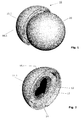
- Fig. 1
- eine erste Ausführungsform der Erfindung in einer perspektivischen Ansicht, wobei im gezeigten Moment ein Tennisball gegen das Unterteil der Ballmarkierungsvorrichtung gedrückt wird;
- Fig. 2
- eine perspektivische Ansicht des Unterteils der ersten Ausführungsform der Erfindung;
- Fig. 3
- eine Explosionszeichnung der ersten Ausführungsform der Erfindung;
- Fig. 4
- eine perspektivische Ansicht einer Schablone, gemäss Erfindung.
- Im Folgenden wird eine bevorzugte Ausführungsform der Erfindung beschrieben, die speziell für das Markieren von Tennisbällen 20 ausgelegt ist. Die Erfindung kann aber auch zum Markieren anderer Bälle (Fussbälle, Hand- oder Volleybälle, oder Golfbälle) eingesetzt werden. Dabei werden aber vorzugsweise
die Dimensionen der Ballmarkierungsvorrichtung 10 entsprechend gewählt. - Die erfindungsgemässe Ballmarkierungsvorrichtung 10 weist ein zweiteiliges Gehäuse mit einem Unterteil 11.1 und einem Oberteil 11.2 auf. Im Unterteil 11.1 befindet sich eine Art Stempelkissen 13 und ein Tintenreservoir 15, die in der in
Fig. 3 gezeigten Reihenfolge im Unterteil 11.1 des Gehäuses angeordnet sind. Das Tintenreservoir 15 steht mit dem Stempelkissen 13 in Fluidverbindung, damit stets ausreichend Tintenflüssigkeit, die im Tintenreservoir 15 gespeichert ist, in das Stempelkissen nachfliessen oder nachgesaugt werden kann. Die Anordnung und Ausführung dieser Elemente ist ähnlich wie bei einem Stempelkissen, wobei Wert darauf gelegt wird, dass ein Auslaufen des Stempels 10 auch bei verkehrter Lagerung nicht auftritt. - Nach oben hin wird das Stempelkissen 13 durch eine austauschbare Schablone 12 begrenzt, die so in dem Unterteil 11.1 des Gehäuses angeordnet ist, dass das Stempelkissen 13 und das Tintenreservoir 15 untereinander unterhalb der Schablone 12 in dem Unterteil 11.1 des Gehäuses sitzen. Ein Teil des Stempelkissens 13 ist durch eine (z.B. herzförmige) Öffnung 12.1 der Schablone 12 hindurch zugänglich, wie in
Fig. 2 angedeutet. InFig. 2 ist das Stempelkissen 13 schwarz dargestellt. - Die Schablone 12 kann manuell in dem Unterteil 11.1 des Gehäuses befestigt werden. Vorzugsweise wird die Schablone 12 durch einen Ring 14 oder eine Klammer am Unterteil 11.1 befestigt. Die Schablone 12 kann fix mit dem Ringelement 14 verschweisst, verklebt oder verpresst sein. Es ist aber auch möglich, die Schablone 12 lose auf das Stempelkissen 13 zu legen und sie dann mit dem Ringelement 14 festzuklemmen. Die Ausführungsform mit der lose eingelegten Schablone 12 hat den Vorteil, dass die Schablone 12 selbst zugeschnitten werden kann. Mit einer Schere oder einem Stanzwerkzeug kann man ein Symbol aus der Schablone 12 ausschneiden oder ausstanzen. Man kann auch durch das Zusammenfalten der Schablone 12, wie bei einem Scherenschnitt, symmetrische Symbole ausschneiden.
- Das Gehäuse umfasst weiterhin ein Oberteil 11.2, das manuell entfernt werden kann, um einen Zugang zu der Öffnung 12.1 der Schablone 12 zu ermöglichen. Wenn das Oberteil 11.2 entfernt wurde, so kann das Unterteil 11.1 der Ballmarkierungsvorrichtung 10 mit der Öffnung 12.1 der Schablone 12 gegen einen Ball 20 gedrückt werden, oder es kann ein Ball 20 gegen die
Öffnung 12.1 der Schablone 12 gedrückt werden, wie inFig. 1 gezeigt. - Die Dimensionen des Gehäuses 11.1, 11.2 und die Grösse und Platzierung der Öffnung 12.1 werden so gewählt, dass der Ball 20 mit seinem
Mantel oder seiner Hülle ein kleines Stück weit in die Öffnung 12.1 eindringt, um so mit Stempelkissen 13 und der Tinte, die im Stempelkissen 13 ist, in Kontakt zu geraten. Bei dem gezeigten Beispiel wird ein schwarzer, herzförmiger Abdruck auf den Ball 20 aufgebracht. Es können aber auch andere Symbole verwendet werden. - Vorzugsweise weist das Unterteil 11.1 des Gehäuses und das Oberteil 11.2 des Gehäuses je die Form einer hohlen Halbkugel auf. Damit ähnelt das Gehäuse, vor allem wenn es zusammengesetzt ist, einem Tennisball 20.
- Das Oberteil 11.2 und das Unterteil 11.1 weisen vorzugsweise Bajonettverschlusselemente 16.1, 16.2 auf, wie in den
Figuren 1 bis 3 zu erkennen ist. Das Oberteil 11.2 und das Unterteil 11.1 können dann durch eine manuelle Drehbewegung miteinander verbunden oder voneinander getrennt werden. Die Bajonettverbindung mittels Bajonettverschlusselementen 16.1, 16.2 hat den Vorteil, dass beide Hälften 11.1, 11.2 des Gehäuses sicher und einfach aneinander befestigt werden können. Ein Auslaufen der Tinte oder ein Verschmutzen von Taschen in denen die Ballmarkierungsvorrichtung 10 aufbewahrt wird, kann so verhindert werden. - Die Schablone 12 sitzt vorzugsweise in einem Ringelement 14, das vorzugsweise durch eine Drehbewegung in dem Unterteil 11.1 befestigbar ist. Es ist aber auch denkbar, ein Ringelement 14 anzubieten, das als integraler Bestandteil die Schablone 12 umfasst. Vorzugsweise wird die Ballmarkierungsvorrichtung 10 mit mehreren verschiedenen Schablonen 12, oder mit mehreren verschiedenen Ringen 14 mit Schablonen 12, angeboten.
- Das Ringelement 14 kann kleine Griffelemente 14.1 aufweisen, die z.B. auch als Führungselemente 14.1 oder Zentrierelemente dienen können, um eine Zentrierung des Balles 20 beim Gegendrücken zu erreichen. Die Griffelemente 14.1 erlauben es das Ringelement 14 mit den Fingern zu packen und in das Unterteil 11.1 einzusetzen oder einzuklemmen. In
Fig. 2 sind diese Griffelemente 14.1 als zungenförmige Laschen gezeigt, die tangential gegen einen Ball 20 drücken, um ihn zu führen. In einer anderen Ausführungsform kann das Ringelement 14 mit den Griffelementen 14.1 gehalten und in das Unterteil 11.1 eingeschraubt werden. Das Einschrauben kann mit einem Gewinde oder mit einem Bajonettverschluss erfolgen. - Vorzugsweise sitzt die Schablone 12 konzentrisch zu einer zentralen Achse der Kugel, die aus Unterteil 11.1 und Oberteil 11.2 des Gehäuses gebildet wird. Damit ist gewährleistet, dass auch die Öffnung 12.1 der Schablone 12 mittig liegt. Die Schablone 12 weist vorzugsweise eine leicht dehnbare Folie oder Membran auf, die hier vereinfachend als Membran bezeichnet wird. Vorzugsweise kann diese Membran aufgerollt oder gefaltet werden. Besonders bevorzugt sind Membranen, die mit einer Schere geschnitten oder einem Stanzwerkzeug ausgestanzt werden können. In dieser Membran kann die Öffnung 12.1 definiert sein.
- Gemäss einer weiteren Ausführungsform der Erfindung wird die Schablone mit einer Membran ohne Öffnung 12.1 geliefert. Der Anwender kann dann eine eigene Öffnung 12.1 in der Membran herstellen (z.B. mit einer Schere oder einem Stanzwerkzeug).
- Zum Markieren oder Bedrucken von Bällen kommt vorzugsweise wasserfeste Tinte zum Einsatz. Das Tintenreservoir 15 ist daher speziell zum Aufnehmen wasserfester Tinte ausgelegt.
- Der Durchmesser eines Tennisballs beträgt zwischen 6,35 cm und 6,67 cm. Der Stempel 10 zeichnet sich dadurch aus, dass jede der Halbkugeln 11.1, 11.2 einen Durchmesser hat, der grösser ist als 6 cm und kleiner ist als 10 cm.
- Vorzugsweise ist der Durchmesser des Stempelgehäuses 11.1, 11.2 ca. 10 bis 20% grösser als der Durchmesser des zu markierenden Balles 20. Diese Angabe gilt für kleine Bälle 20. Bei Fussbällen kann die Ballmarkierungsvorrichtung deutlich kleiner sein, als der Ball selbst.
- Die Ballmarkierungsvorrichtung 10 weist somit ein Gehäuse 11.1, 11.2, ein Stempelkissen 13 und ein Tintenreservoir 15 auf, wobei das Tintenreservoir 15 mit dem Stempelkissen 13 in Fluidverbindung steht. Die Ballmarkierungsvorrichtung 10 weist eine austauschbare Schablone 12 auf, die so in einem Unterteil 11.1 des Gehäuses angeordnet ist, dass das Stempelkissen 13 und das Tintenreservoir 15 untereinander unterhalb der Schablone 12 in dem Unterteil 11.1 des Gehäuses sitzen. Ein Teil des Stempelkissens 13 ist durch eine Öffnung 12.1 der Schablone 12 hindurch zugänglich. Die Schablone 12 kann manuell in dem Unterteil 11.1 des Gehäuses befestigt werden. Weiterhin umfasst das Gehäuse ein Oberteil 11.2, das manuell entfernt werden kann, um einen Zugang zu der Öffnung 12.1 der Schablone 12 zu ermöglichen. In geöffnetem Zustand kann das Unterteil 11.1 der Ballmarkierungsvorrichtung 10 mit der Öffnung der Schablone 12 gegen einen Ball 20, oder ein Ball 20 kann gegen die Öffnung 12.1 der Schablone 12 gedrückt werden.
- Neben den Austauschen/Ersetzen der Schablone 12, kann auch die Stempelfarbe im Stempelkissen je nach Bedarf geändert werden. Durch das Austauschen der Stempelfarbe oder des Stempelkissens kann man zum Beispiel mit der in
Fig. 4 gezeigten Schablone 12 grüne, blaue und rote Herzen aufstempeln oder auftragen. Beim Verwenden einer anderer Schablone 12 mit einem anderen Symbol kann man auch andere Symbole aufstempeln. - Durch das Austauschen/Ersetzen der Schablone 12 (z.B. mit anderen Symbolen) und der Stempelfarbe oder des Stempelkissens 13 sind zahlreiche Kombinationsmöglichkeiten gegeben.
- In einer weiteren Ausführungsform der Erfindung sind die beiden Tennisballstempelhälften (d.h. das Unterteil 11.1 und das Oberteil 11.2) identisch konstruiert. In diesem Fall beinhalten beide Teile 11.1, 11.2 ein Ringelement 14, ein Stempelkissen 13, ein Tintenreservoir 15 und eine Schablone 12. Damit stehen pro Stempel 10 zwei Stempelmöglichkeiten (eine pro "Halbkugel" 11.1, 11.2) zur Verfügung.
- Die Unterteile 11.1 und Oberteile 11.2 können frei austauschbar sein und können daher dank Bajonettverschluss beliebig zusammengefügt werden.
- Gemäss einer weiteren Ausführungsform der Erfindung kann das Unterteil 11.1 oder das Oberteil 11.2 innen so ausgestaltet sein, dass eine oder mehrere Schablonen 12 in diesem Teil gespeichert werden können. Falls es sich bei den Schablonen 12 um dünne und flexible (eventuell gummiartige) membranartige Elemente handelt, so können an dem Ringelement 14 Mittel zu Einspannen oder Aufspannen der Schablone 12 vorgesehen sein. Vorzugsweise kann diese Art von Schablone 12 einen Durchmesser haben, der etwas grösser ist als der Durchmesser des Ringelements 14. Zum Einspannen der Schablone 12 legt man das Ringelement 14 auf die Schablone 12 und fasst die Schablone 12 so, dass deren äusserer Rand nach oben verläuft. Beim Eindrehen des Ringelements 14 in eine der Kugelhälften 11.1 oder 11.2 wird dann der äussere Rand der Schablone 12 im Zwischenraum zwischen dem Ringelement 14 und der Innenwand des entsprechenden Unterteils 11.1 oder Oberteils 11.2
eingeklemmt/fixiert. - Vorzugsweise werden das Unterteil 11.1 und das Oberteil 11.2 und/oder die Schablone 12 aus spritzgegossenem Kunststoff gefertigt, bzw. das Unterteil 11.1 und das Oberteil 11.2 und/oder die Schablone 12 wird im Spritzgussverfahren hergestellt. Besonders bevorzugt sind dünne und flexible (gummiartige) Membranen als Schablone 12.
Claims (10)
- Tragbare Ballmarkierungsvorrichtung (10) mit einem Gehäuse mit Unterteil und einem
Stempelkissen (13), wobei- die Ballmarkierungsvorrichtung ein Tintenreservoir (15) umfasst, wobei- das Tintenreservoir (15) mit dem Stempelkissen (13) in Fluidverbindung steht,- die Ballmarkierungsvorrichtung (10) eine austauschbare Schablone (12) aufweist, die so in dem Unterteil (11.1) des Gehäuses
angeordnet ist, dass das Stempelkissen (13) unterhalb der Schablone (12) und oberhalb des Tintenreservoirs (15) in dem Unterteil (11.1) des Gehäuses angeordnet ist, wobei ein Teil des Stempelkissens (13) durch eine Öffnung (12.1) der Schablone (12) hindurch zugänglich ist,- die Schablone (12) am Unterteil (11.1) des Gehäuses und manuell lösbar fixiert ist,- das Gehäuse ein Oberteil (11.2) umfasst, das manuell entfernt werden kann, um einen Zugang zu der Öffnung (12.1) der Schablone (12) zu ermöglichen, um das Unterteil (11.1) mit der Öffnung der Schablone (12) gegen einen Ball (20), oder einen Ball (20) gegen die Öffnung
(12.1) der Schablone (12) drücken zu können. - Ballmarkierungsvorrichtung (10) nach Anspruch 1, dadurch gekennzeichnet, dass das Unterteil (11.1) des Gehäuses und das Oberteil (11.2) des Gehäuses je die Form einer hohlen Halbkugel haben.
- Ballmarkierungsvorrichtung (10) nach Anspruch 1 oder 2, dadurch gekennzeichnet, dass das Oberteil (11.2) und das Unterteil (11.1) Bajonettverschlusselemente (16.1, 16.2) aufweisen, wobei Oberteil (11.2) und Unterteil (11.1) durch eine manuelle Drehbewegung miteinander verbunden oder voneinander getrennt werden können.
- Ballmarkierungsvorrichtung (10) nach Anspruch 1 oder 2, dadurch gekennzeichnet, dass die Schablone (12) in einem Ringelement (14) sitzt, das vorzugsweise durch eine Drehbewegung in dem Unterteil (11.1) befestigbar ist.
- Ballmarkierungsvorrichtung (10) nach Anspruch 4, dadurch gekennzeichnet, dass das Ringelement (14) Griffelemente (14.1) aufweist, um das Ringelement (14) in das Unterteil (11.1) einsetzen, einklemmen oder einschrauben zu können.
- Ballmarkierungsvorrichtung (10) nach einem der Ansprüche 1 bis 5, dadurch gekennzeichnet, dass sie mehrere Schablonen (12) mit unterschiedlich geformten Öffnungen (12.1) aufweist, die austauschbar sind.
- Ballmarkierungsvorrichtung (10) nach einem der Ansprüche 1 bis 6, dadurch gekennzeichnet, dass das Tintenreservoir (15) zum Aufnehmen wasserfester Tinte ausgelegt ist.
- Ballmarkierungsvorrichtung (10) nach einem der Ansprüche 1 bis 6, dadurch gekennzeichnet, dass sie zum Markieren von Tennisbällen (20) ausgelegt ist, wobei das Tintenreservoir (15) mit wasserfester Tinte gefüllt ist.
- Ballmarkierungsvorrichtung (10) nach einem der Ansprüche 2 bis 6, dadurch gekennzeichnet, dass jede der Halbkugeln einen Durchmesser hat, der grösser ist als 6 cm und kleiner ist als 10 cm.
- Ballmarkierungsvorrichtung (10) nach einem der Ansprüche 2 bis 6, dadurch gekennzeichnet, dass beide Halbkugeln identisch ausgeführt sind.
Applications Claiming Priority (2)
| Application Number | Priority Date | Filing Date | Title |
|---|---|---|---|
| CH72008 | 2008-01-04 | ||
| PCT/EP2008/067313 WO2009087011A2 (de) | 2008-01-04 | 2008-12-11 | Schablonenstempel zum markieren von bällen |
Publications (2)
| Publication Number | Publication Date |
|---|---|
| EP2227397A2 EP2227397A2 (de) | 2010-09-15 |
| EP2227397B1 true EP2227397B1 (de) | 2016-11-30 |
Family
ID=39985913
Family Applications (1)
| Application Number | Title | Priority Date | Filing Date |
|---|---|---|---|
| EP08869244.7A Not-in-force EP2227397B1 (de) | 2008-01-04 | 2008-12-11 | Schablonenstempel zum markieren von bällen |
Country Status (4)
| Country | Link |
|---|---|
| US (1) | US20100313770A1 (de) |
| EP (1) | EP2227397B1 (de) |
| DE (1) | DE202008018356U1 (de) |
| WO (1) | WO2009087011A2 (de) |
Families Citing this family (2)
| Publication number | Priority date | Publication date | Assignee | Title |
|---|---|---|---|---|
| ES2523974T3 (es) | 2011-05-13 | 2014-12-03 | Annette Lehmann | Dispositivo de marcación para marcar pelotas, uso de tal dispositivo de marcación y procedimiento para proporcionar tal dispositivo de marcación |
| AU353576S (en) * | 2013-05-17 | 2014-02-07 | Adminimum AG | Stamphousing |
Family Cites Families (12)
| Publication number | Priority date | Publication date | Assignee | Title |
|---|---|---|---|---|
| US1236801A (en) * | 1915-11-01 | 1917-08-14 | Superior Type Company | Hand-stamp. |
| DE391612C (de) * | 1921-12-18 | 1924-03-08 | George Thomas Pritchard | Schablonenstempel |
| US1537685A (en) * | 1923-03-26 | 1925-05-12 | Ladd Walter Porter | Stencil marker |
| DE2507855A1 (de) * | 1975-02-24 | 1976-09-02 | Manfred Seibold | Vorrichtung zum markieren von gegenstaenden |
| DE3118672A1 (de) * | 1981-05-12 | 1982-12-02 | Werner 4236 Haminkeln Puckert | Stempel, insbesondere fuer das signieren von tennisbaellen |
| US4441422A (en) * | 1982-01-08 | 1984-04-10 | Lionel Dreeben | Capillary stencil printer with improved replenishment of the printing pad and re-inking of the reservoir |
| US5743180A (en) * | 1997-04-03 | 1998-04-28 | Arnke; Michael C. | Golf ball marker |
| US6379271B1 (en) * | 1999-03-26 | 2002-04-30 | Michael C. Arnke | Golf accessory |
| US6189451B1 (en) * | 1999-08-03 | 2001-02-20 | Wolfgang Pichler | Stamp for providing imprint on bulging surface |
| US6829989B2 (en) * | 2003-01-22 | 2004-12-14 | Golf Gifts & Gallery Inc. | Apparatus and method for marking a golf ball |
| EP1604834A1 (de) * | 2004-04-06 | 2005-12-14 | Nuovo AG Eierverarbeitungsmaschinen | Stempel zum Markieren von Agrarprodukten |
| US8006615B1 (en) * | 2007-12-05 | 2011-08-30 | Zoya, Inc. | Stencil stamp set |
-
2008
- 2008-12-11 US US12/811,748 patent/US20100313770A1/en not_active Abandoned
- 2008-12-11 DE DE202008018356U patent/DE202008018356U1/de not_active Expired - Lifetime
- 2008-12-11 EP EP08869244.7A patent/EP2227397B1/de not_active Not-in-force
- 2008-12-11 WO PCT/EP2008/067313 patent/WO2009087011A2/de not_active Ceased
Also Published As
| Publication number | Publication date |
|---|---|
| US20100313770A1 (en) | 2010-12-16 |
| WO2009087011A3 (de) | 2009-09-24 |
| WO2009087011A2 (de) | 2009-07-16 |
| DE202008018356U1 (de) | 2013-04-24 |
| EP2227397A2 (de) | 2010-09-15 |
Similar Documents
| Publication | Publication Date | Title |
|---|---|---|
| EP2227397B1 (de) | Schablonenstempel zum markieren von bällen | |
| DE102016202529A1 (de) | Vorrichtung zum Aufbringen von Kleb- und oder Dichtstoff | |
| AT8968U1 (de) | Längliche stempelvorrichtung | |
| EP2522524B1 (de) | Markierungsvorrichtung zum Markieren von Bällen, Verwendung einer solchen Markierungsvorrichtung und Verfahren zum Bereitstellen einer solchen Markierungsvorrichtung | |
| DE3538685A1 (de) | Schutzhuelle fuer ausweiskarten oder dergleichen | |
| DE2907552A1 (de) | Vorrichtung zur markierung von spielscheinen, insbesondere von lotto-spielscheinen u.dgl. | |
| DE202016103934U1 (de) | Schreibgerät mit Zwischenstück | |
| US5353704A (en) | Stamping apparatus and method for forming a stamp and stamping using elongated members | |
| DE202020002554U1 (de) | Gefäßabdeckung mit Zusatzfunktion | |
| DE202009002452U1 (de) | Vorrichtung zur Erstellung von 8- und 6-Punkt Braille-Zeichen | |
| DE102009044327A1 (de) | Fahrradwerkzeug mit Kettendemontagefunktion | |
| DE2829935B2 (de) | Abklappbarer Zeilenrichter für Schreibmaschinen | |
| DE102005038259A1 (de) | Zahnbürste | |
| DE959828C (de) | Stempelkasten fuer Tieraerzte und Fleischbeschauer | |
| DE202005009196U1 (de) | Schreibstift mit veränderbarem Griff | |
| DE29912238U1 (de) | Dokumentenhülle | |
| DE102004024062B4 (de) | Tintenpatronenhalterung | |
| DE202009008331U1 (de) | Handgriff für Werkzeug | |
| DE202007005512U1 (de) | Stempel mit auswechselbarem Stempeleinsatz | |
| DE1177655B (de) | Handstempelhalter | |
| DE202020101866U1 (de) | Befestigungsmodul für einen Kaffeeautomaten | |
| DE202006007494U1 (de) | Veränderbarer Muster-Stempel | |
| DE7406788U (de) | Klosettsitz mit Entlüftung und Filter | |
| DE202005017960U1 (de) | Aufnahmeschale für wenigstens ein medizinisches Gerät, insbesondere Endoskop, sowie Auskleidungsteil hierfür | |
| DE102006047999A1 (de) | Vorrichtung zum Markieren von Gegenständen |
Legal Events
| Date | Code | Title | Description |
|---|---|---|---|
| PUAI | Public reference made under article 153(3) epc to a published international application that has entered the european phase |
Free format text: ORIGINAL CODE: 0009012 |
|
| 17P | Request for examination filed |
Effective date: 20100713 |
|
| AK | Designated contracting states |
Kind code of ref document: A2 Designated state(s): AT BE BG CH CY CZ DE DK EE ES FI FR GB GR HR HU IE IS IT LI LT LU LV MC MT NL NO PL PT RO SE SI SK TR |
|
| AX | Request for extension of the european patent |
Extension state: AL BA MK RS |
|
| DAX | Request for extension of the european patent (deleted) | ||
| 17Q | First examination report despatched |
Effective date: 20141204 |
|
| REG | Reference to a national code |
Ref country code: DE Ref legal event code: R079 Ref document number: 502008014853 Country of ref document: DE Free format text: PREVIOUS MAIN CLASS: B41K0001320000 Ipc: B41K0001280000 |
|
| GRAP | Despatch of communication of intention to grant a patent |
Free format text: ORIGINAL CODE: EPIDOSNIGR1 |
|
| RIC1 | Information provided on ipc code assigned before grant |
Ipc: B41K 1/28 20060101AFI20160531BHEP Ipc: A63B 45/02 20060101ALI20160531BHEP Ipc: B41K 1/32 20060101ALI20160531BHEP |
|
| INTG | Intention to grant announced |
Effective date: 20160622 |
|
| GRAS | Grant fee paid |
Free format text: ORIGINAL CODE: EPIDOSNIGR3 |
|
| GRAA | (expected) grant |
Free format text: ORIGINAL CODE: 0009210 |
|
| AK | Designated contracting states |
Kind code of ref document: B1 Designated state(s): AT BE BG CH CY CZ DE DK EE ES FI FR GB GR HR HU IE IS IT LI LT LU LV MC MT NL NO PL PT RO SE SI SK TR |
|
| REG | Reference to a national code |
Ref country code: CH Ref legal event code: EP Ref country code: GB Ref legal event code: FG4D Free format text: NOT ENGLISH |
|
| REG | Reference to a national code |
Ref country code: AT Ref legal event code: REF Ref document number: 849416 Country of ref document: AT Kind code of ref document: T Effective date: 20161215 |
|
| REG | Reference to a national code |
Ref country code: IE Ref legal event code: FG4D Free format text: LANGUAGE OF EP DOCUMENT: GERMAN |
|
| REG | Reference to a national code |
Ref country code: FR Ref legal event code: PLFP Year of fee payment: 9 |
|
| REG | Reference to a national code |
Ref country code: CH Ref legal event code: NV Representative=s name: OK PAT AG PATENTE MARKEN LIZENZEN, CH |
|
| REG | Reference to a national code |
Ref country code: DE Ref legal event code: R096 Ref document number: 502008014853 Country of ref document: DE |
|
| PGFP | Annual fee paid to national office [announced via postgrant information from national office to epo] |
Ref country code: GB Payment date: 20161221 Year of fee payment: 9 |
|
| PG25 | Lapsed in a contracting state [announced via postgrant information from national office to epo] |
Ref country code: LV Free format text: LAPSE BECAUSE OF FAILURE TO SUBMIT A TRANSLATION OF THE DESCRIPTION OR TO PAY THE FEE WITHIN THE PRESCRIBED TIME-LIMIT Effective date: 20161130 |
|
| PGFP | Annual fee paid to national office [announced via postgrant information from national office to epo] |
Ref country code: FR Payment date: 20161229 Year of fee payment: 9 |
|
| REG | Reference to a national code |
Ref country code: LT Ref legal event code: MG4D |
|
| REG | Reference to a national code |
Ref country code: NL Ref legal event code: MP Effective date: 20161130 |
|
| PG25 | Lapsed in a contracting state [announced via postgrant information from national office to epo] |
Ref country code: NO Free format text: LAPSE BECAUSE OF FAILURE TO SUBMIT A TRANSLATION OF THE DESCRIPTION OR TO PAY THE FEE WITHIN THE PRESCRIBED TIME-LIMIT Effective date: 20170228 Ref country code: SE Free format text: LAPSE BECAUSE OF FAILURE TO SUBMIT A TRANSLATION OF THE DESCRIPTION OR TO PAY THE FEE WITHIN THE PRESCRIBED TIME-LIMIT Effective date: 20161130 Ref country code: GR Free format text: LAPSE BECAUSE OF FAILURE TO SUBMIT A TRANSLATION OF THE DESCRIPTION OR TO PAY THE FEE WITHIN THE PRESCRIBED TIME-LIMIT Effective date: 20170301 Ref country code: LT Free format text: LAPSE BECAUSE OF FAILURE TO SUBMIT A TRANSLATION OF THE DESCRIPTION OR TO PAY THE FEE WITHIN THE PRESCRIBED TIME-LIMIT Effective date: 20161130 |
|
| PG25 | Lapsed in a contracting state [announced via postgrant information from national office to epo] |
Ref country code: ES Free format text: LAPSE BECAUSE OF FAILURE TO SUBMIT A TRANSLATION OF THE DESCRIPTION OR TO PAY THE FEE WITHIN THE PRESCRIBED TIME-LIMIT Effective date: 20161130 Ref country code: PT Free format text: LAPSE BECAUSE OF FAILURE TO SUBMIT A TRANSLATION OF THE DESCRIPTION OR TO PAY THE FEE WITHIN THE PRESCRIBED TIME-LIMIT Effective date: 20170330 Ref country code: PL Free format text: LAPSE BECAUSE OF FAILURE TO SUBMIT A TRANSLATION OF THE DESCRIPTION OR TO PAY THE FEE WITHIN THE PRESCRIBED TIME-LIMIT Effective date: 20161130 Ref country code: HR Free format text: LAPSE BECAUSE OF FAILURE TO SUBMIT A TRANSLATION OF THE DESCRIPTION OR TO PAY THE FEE WITHIN THE PRESCRIBED TIME-LIMIT Effective date: 20161130 Ref country code: FI Free format text: LAPSE BECAUSE OF FAILURE TO SUBMIT A TRANSLATION OF THE DESCRIPTION OR TO PAY THE FEE WITHIN THE PRESCRIBED TIME-LIMIT Effective date: 20161130 Ref country code: BE Free format text: LAPSE BECAUSE OF NON-PAYMENT OF DUE FEES Effective date: 20161231 |
|
| PG25 | Lapsed in a contracting state [announced via postgrant information from national office to epo] |
Ref country code: NL Free format text: LAPSE BECAUSE OF FAILURE TO SUBMIT A TRANSLATION OF THE DESCRIPTION OR TO PAY THE FEE WITHIN THE PRESCRIBED TIME-LIMIT Effective date: 20161130 |
|
| PG25 | Lapsed in a contracting state [announced via postgrant information from national office to epo] |
Ref country code: EE Free format text: LAPSE BECAUSE OF FAILURE TO SUBMIT A TRANSLATION OF THE DESCRIPTION OR TO PAY THE FEE WITHIN THE PRESCRIBED TIME-LIMIT Effective date: 20161130 Ref country code: DK Free format text: LAPSE BECAUSE OF FAILURE TO SUBMIT A TRANSLATION OF THE DESCRIPTION OR TO PAY THE FEE WITHIN THE PRESCRIBED TIME-LIMIT Effective date: 20161130 Ref country code: RO Free format text: LAPSE BECAUSE OF FAILURE TO SUBMIT A TRANSLATION OF THE DESCRIPTION OR TO PAY THE FEE WITHIN THE PRESCRIBED TIME-LIMIT Effective date: 20161130 Ref country code: CZ Free format text: LAPSE BECAUSE OF FAILURE TO SUBMIT A TRANSLATION OF THE DESCRIPTION OR TO PAY THE FEE WITHIN THE PRESCRIBED TIME-LIMIT Effective date: 20161130 Ref country code: SK Free format text: LAPSE BECAUSE OF FAILURE TO SUBMIT A TRANSLATION OF THE DESCRIPTION OR TO PAY THE FEE WITHIN THE PRESCRIBED TIME-LIMIT Effective date: 20161130 |
|
| PG25 | Lapsed in a contracting state [announced via postgrant information from national office to epo] |
Ref country code: IT Free format text: LAPSE BECAUSE OF FAILURE TO SUBMIT A TRANSLATION OF THE DESCRIPTION OR TO PAY THE FEE WITHIN THE PRESCRIBED TIME-LIMIT Effective date: 20161130 Ref country code: BG Free format text: LAPSE BECAUSE OF FAILURE TO SUBMIT A TRANSLATION OF THE DESCRIPTION OR TO PAY THE FEE WITHIN THE PRESCRIBED TIME-LIMIT Effective date: 20170228 |
|
| REG | Reference to a national code |
Ref country code: DE Ref legal event code: R097 Ref document number: 502008014853 Country of ref document: DE |
|
| PG25 | Lapsed in a contracting state [announced via postgrant information from national office to epo] |
Ref country code: MC Free format text: LAPSE BECAUSE OF FAILURE TO SUBMIT A TRANSLATION OF THE DESCRIPTION OR TO PAY THE FEE WITHIN THE PRESCRIBED TIME-LIMIT Effective date: 20161130 |
|
| REG | Reference to a national code |
Ref country code: IE Ref legal event code: MM4A |
|
| PLBE | No opposition filed within time limit |
Free format text: ORIGINAL CODE: 0009261 |
|
| STAA | Information on the status of an ep patent application or granted ep patent |
Free format text: STATUS: NO OPPOSITION FILED WITHIN TIME LIMIT |
|
| PG25 | Lapsed in a contracting state [announced via postgrant information from national office to epo] |
Ref country code: LU Free format text: LAPSE BECAUSE OF NON-PAYMENT OF DUE FEES Effective date: 20161211 |
|
| 26N | No opposition filed |
Effective date: 20170831 |
|
| PG25 | Lapsed in a contracting state [announced via postgrant information from national office to epo] |
Ref country code: IE Free format text: LAPSE BECAUSE OF NON-PAYMENT OF DUE FEES Effective date: 20161211 Ref country code: SI Free format text: LAPSE BECAUSE OF FAILURE TO SUBMIT A TRANSLATION OF THE DESCRIPTION OR TO PAY THE FEE WITHIN THE PRESCRIBED TIME-LIMIT Effective date: 20161130 |
|
| REG | Reference to a national code |
Ref country code: BE Ref legal event code: MM Effective date: 20161231 |
|
| PG25 | Lapsed in a contracting state [announced via postgrant information from national office to epo] |
Ref country code: CY Free format text: LAPSE BECAUSE OF FAILURE TO SUBMIT A TRANSLATION OF THE DESCRIPTION OR TO PAY THE FEE WITHIN THE PRESCRIBED TIME-LIMIT Effective date: 20161130 Ref country code: HU Free format text: LAPSE BECAUSE OF FAILURE TO SUBMIT A TRANSLATION OF THE DESCRIPTION OR TO PAY THE FEE WITHIN THE PRESCRIBED TIME-LIMIT; INVALID AB INITIO Effective date: 20081211 |
|
| PG25 | Lapsed in a contracting state [announced via postgrant information from national office to epo] |
Ref country code: IS Free format text: LAPSE BECAUSE OF FAILURE TO SUBMIT A TRANSLATION OF THE DESCRIPTION OR TO PAY THE FEE WITHIN THE PRESCRIBED TIME-LIMIT Effective date: 20161130 Ref country code: TR Free format text: LAPSE BECAUSE OF FAILURE TO SUBMIT A TRANSLATION OF THE DESCRIPTION OR TO PAY THE FEE WITHIN THE PRESCRIBED TIME-LIMIT Effective date: 20161130 |
|
| GBPC | Gb: european patent ceased through non-payment of renewal fee |
Effective date: 20171211 |
|
| PG25 | Lapsed in a contracting state [announced via postgrant information from national office to epo] |
Ref country code: MT Free format text: LAPSE BECAUSE OF FAILURE TO SUBMIT A TRANSLATION OF THE DESCRIPTION OR TO PAY THE FEE WITHIN THE PRESCRIBED TIME-LIMIT Effective date: 20161130 |
|
| REG | Reference to a national code |
Ref country code: FR Ref legal event code: ST Effective date: 20180831 |
|
| PG25 | Lapsed in a contracting state [announced via postgrant information from national office to epo] |
Ref country code: FR Free format text: LAPSE BECAUSE OF NON-PAYMENT OF DUE FEES Effective date: 20180102 |
|
| PG25 | Lapsed in a contracting state [announced via postgrant information from national office to epo] |
Ref country code: GB Free format text: LAPSE BECAUSE OF NON-PAYMENT OF DUE FEES Effective date: 20171211 |
|
| REG | Reference to a national code |
Ref country code: CH Ref legal event code: PFUS Owner name: LEHMANN, ANNETTE, CH Free format text: FORMER OWNER: LEHMANN, ANNETTE, CH |
|
| PGFP | Annual fee paid to national office [announced via postgrant information from national office to epo] |
Ref country code: AT Payment date: 20211129 Year of fee payment: 14 Ref country code: DE Payment date: 20211116 Year of fee payment: 14 |
|
| PGFP | Annual fee paid to national office [announced via postgrant information from national office to epo] |
Ref country code: CH Payment date: 20211122 Year of fee payment: 14 |
|
| REG | Reference to a national code |
Ref country code: DE Ref legal event code: R119 Ref document number: 502008014853 Country of ref document: DE |
|
| REG | Reference to a national code |
Ref country code: CH Ref legal event code: PL |
|
| REG | Reference to a national code |
Ref country code: AT Ref legal event code: MM01 Ref document number: 849416 Country of ref document: AT Kind code of ref document: T Effective date: 20221211 |
|
| PG25 | Lapsed in a contracting state [announced via postgrant information from national office to epo] |
Ref country code: LI Free format text: LAPSE BECAUSE OF NON-PAYMENT OF DUE FEES Effective date: 20221231 Ref country code: DE Free format text: LAPSE BECAUSE OF NON-PAYMENT OF DUE FEES Effective date: 20230701 Ref country code: CH Free format text: LAPSE BECAUSE OF NON-PAYMENT OF DUE FEES Effective date: 20221231 Ref country code: AT Free format text: LAPSE BECAUSE OF NON-PAYMENT OF DUE FEES Effective date: 20221211 |