EP2228122B1 - Verfahren und Reaktor zum Entfernen von VOC aus Gasströmen - Google Patents
Verfahren und Reaktor zum Entfernen von VOC aus Gasströmen Download PDFInfo
- Publication number
- EP2228122B1 EP2228122B1 EP20090153651 EP09153651A EP2228122B1 EP 2228122 B1 EP2228122 B1 EP 2228122B1 EP 20090153651 EP20090153651 EP 20090153651 EP 09153651 A EP09153651 A EP 09153651A EP 2228122 B1 EP2228122 B1 EP 2228122B1
- Authority
- EP
- European Patent Office
- Prior art keywords
- compartment
- gas flow
- gas
- reactor
- heated
- Prior art date
- Legal status (The legal status is an assumption and is not a legal conclusion. Google has not performed a legal analysis and makes no representation as to the accuracy of the status listed.)
- Active
Links
Images




Classifications
-
- B—PERFORMING OPERATIONS; TRANSPORTING
- B01—PHYSICAL OR CHEMICAL PROCESSES OR APPARATUS IN GENERAL
- B01D—SEPARATION
- B01D53/00—Separation of gases or vapours; Recovering vapours of volatile solvents from gases; Chemical or biological purification of waste gases, e.g. engine exhaust gases, smoke, fumes, flue gases, aerosols
- B01D53/34—Chemical or biological purification of waste gases
- B01D53/74—General processes for purification of waste gases; Apparatus or devices specially adapted therefor
- B01D53/86—Catalytic processes
- B01D53/88—Handling or mounting catalysts
- B01D53/885—Devices in general for catalytic purification of waste gases
-
- B—PERFORMING OPERATIONS; TRANSPORTING
- B01—PHYSICAL OR CHEMICAL PROCESSES OR APPARATUS IN GENERAL
- B01D—SEPARATION
- B01D2255/00—Catalysts
- B01D2255/10—Noble metals or compounds thereof
- B01D2255/102—Platinum group metals
- B01D2255/1021—Platinum
-
- B—PERFORMING OPERATIONS; TRANSPORTING
- B01—PHYSICAL OR CHEMICAL PROCESSES OR APPARATUS IN GENERAL
- B01D—SEPARATION
- B01D2255/00—Catalysts
- B01D2255/10—Noble metals or compounds thereof
- B01D2255/102—Platinum group metals
- B01D2255/1023—Palladium
-
- B—PERFORMING OPERATIONS; TRANSPORTING
- B01—PHYSICAL OR CHEMICAL PROCESSES OR APPARATUS IN GENERAL
- B01D—SEPARATION
- B01D2257/00—Components to be removed
- B01D2257/30—Sulfur compounds
- B01D2257/302—Sulfur oxides
-
- B—PERFORMING OPERATIONS; TRANSPORTING
- B01—PHYSICAL OR CHEMICAL PROCESSES OR APPARATUS IN GENERAL
- B01D—SEPARATION
- B01D2257/00—Components to be removed
- B01D2257/30—Sulfur compounds
- B01D2257/306—Organic sulfur compounds, e.g. mercaptans
-
- B—PERFORMING OPERATIONS; TRANSPORTING
- B01—PHYSICAL OR CHEMICAL PROCESSES OR APPARATUS IN GENERAL
- B01D—SEPARATION
- B01D2257/00—Components to be removed
- B01D2257/70—Organic compounds not provided for in groups B01D2257/00 - B01D2257/602
- B01D2257/708—Volatile organic compounds V.O.C.'s
-
- B—PERFORMING OPERATIONS; TRANSPORTING
- B01—PHYSICAL OR CHEMICAL PROCESSES OR APPARATUS IN GENERAL
- B01D—SEPARATION
- B01D2257/00—Components to be removed
- B01D2257/90—Odorous compounds not provided for in groups B01D2257/00 - B01D2257/708
Definitions
- the present invention is directed to a process for the removal of volatile organic compounds from gas flows by catalytic decomposition or burning, and to a reactor suitable for this process.
- Oxidation converts them to carbon dioxide, water and sulphur dioxide.
- the sulphur dioxide can only be smelled in much higher concentrations, so that it is possible to prevent serious smell problems by oxidation of sulphur compounds in gas flows.
- a major problem in the purification of gas flows by oxidation is the fact that the gas flow has to be raised to a sufficiently high temperature.
- oxidation requires temperatures of 800°C or more. It is clear that the whole of the gas flow has to be brought to such a temperature to oxidize the, often minor, amount of harmful compounds. The heat of combustion of these harmful components is insufficient to bring the gas flow to the required temperature.
- equipment is described wherein the gas flow to be treated is passed through a flame front. The flame is obtained by the burning of fossil fuels. To get complete burning, a heat exchanger has to be used to bring the gas flow to a sufficient high temperature before passing it through the flame.
- An active oxidation catalyst such as platinum or palladium oxide can be used to oxidize noxious compounds at a much lower temperature. Still a temperature of at least 200°C is needed. Even for obtaining such a temperature, the heat of combustion of the impurities present in the gas flow is insufficient. It is possible to solve this problem by adding fuel gas to the gas flow. This increases the costs of the process. In order to minimize the use of fuel gas, a reverse flow technique is also used herein.
- the gas flow is usually fed at one side of the catalyst bed, together with a fuel gas.
- This causes a temperature gradient in the catalyst bed wherein the temperature increases in the downstream direction.
- the heat of combustion is stored in the catalyst bed.
- the direction of the gas flow in the catalyst bed is reversed, so that the gas flow enters the catalyst bed at the location of the highest temperature.
- the gas flow is heated to the minimal combustion temperature of the catalyst.
- the temperature profile of the catalyst changes gradually, resulting therein that the maximal temperature is again obtained at the exit of the catalyst bed.
- the direction of the gas flow is reversed again.
- This process is called a regenerative incinerator system, as the thermal energy present in the treated gas is recovered as much as possible.
- US patents 4,478,808 and 4,877,592 this process is described.
- the thermal energy present in the second compartment, in that catalyst bed is transferred through the gas tight wall to the incoming gas flow.
- the equipment can be much smaller.
- WO 86/02016 a heat exchanger is described, which based on a porous metal body.
- two porous metal bodies have been applied on both sides of a thermally conducting, non-porous, gas tight layer.
- the process according to this publication is directed to carrying out an actual thermal catalytic reaction on the surface of one of the porous metal bodies, whereas in the other compartment a suitable liquid is vaporized. Additional energy is recovered from the gas flow by applying cooling means after the catalytic active body, wherein the tangible thermal energy of the gas flow and the condensation energy of the condensable gases present in the gas flow can be recovered.
- a specific reaction is the oxidation of fuel gas or synthesis gas.
- the present invention is based on the use of a reactor system, comprising at least two compartments, which are present on opposite sides of a gas tight, thermally conducting (usually metal) wall, whereby both compartments have been filled with porous sintered metal material.
- the sintered metal material comprises sintered metal fibres or sintered metal spheres.
- the heat transfer from the second compartment to the gas flow to be purified in the first compartment is such that the temperature in the second compartment does not drop below the minimal required temperature.
- the minimum temperature is selected in such a way that a relative low temperature of about 200°C is sufficient to complete oxidize the contaminants.
- additional gas from a burner is mixed with the gas flow to be treated, generally between the first and second compartment.
- the ratio of the two gas flows is such that the heat of the gas from the burner is sufficient to bring the total gas flow to the temperature needed for the catalytic combustion for the impurities in the gas flow.
- the actual minimal temperature is also determined by the nature of the catalyst in the second compartment.
- the heating element is a gas burner that is fed with a fuel gas, such as methane.
- a fuel gas such as methane.
- methane On locations where there is no natural gas, such as methane, it is possible to use liquefied petroleum gas or butane.
- the gas flow to be treated only is liberated at certain moments of time, such as sewer gas that only is liberated when the sewer becomes filled with water, the fuel gas can be admitted using an electrical switch and in electrical combustion.
- such an amount of fuel gas is mixed with the gas flow to be purified, so that catalytic oxidation of the fuel in the catalyst bed, the temperature is such that also the contaminants in the gas flow to be purified are being oxidized.
- the catalyst and the heat exchanger have been separated.
- the minimum temperature of the oxidation catalyst will generally be higher than needed for oxidation of impurities in the gas flow.
- a normal catalyst bed is used wherein an active component on a support is present. In this case downstream of the catalyst bed there is a porous metal body in suitable thermal contact with the gas tight wall. On the other side of the gas tight wall the first compartment with sintered metal is present. In this way the gas flow to be purified is preheated very efficiently.
- metal gauzes either of a metal which itself is an active oxidation catalyst, such as platinum or palladium, or a metal gauze having applied thereto the catalytically active component.
- the latter embodiment has the advantage of economic savings in the amount of catalytically active component needed.
- An advantage of a metal gauze is that the reaction can be initiated by heating the gauze electrically. In that case the heating element and the catalyst are combined by the use of an electrically heated gauze.
- a third aspect of the invention use is made of electrical heating of the gas flow to be treated.
- An advantage of electrical heating is that such a heating element can be adjusted by accurately. Further, it allows a flameless operation, which may be required under certain conditions.
- electrical heating elements such as a resistance wire or an inductively heated metal wire (copper). Preference is given to an electrically heated gauze. Especially for the purification of relatively small gas flows, electrical heating is very attractive. The equipment can be adjusted very well, whereas the consumption of electrical energy for small gas flows is relatively low.
- the reactor used according to the present invention can be produced using known technology for sintering metals. According to a preferred embodiment, it is possible to start from metal wires or fibres. Nickel wires with a diameter of 50 to 500 ⁇ m are commercially available. These fibres may be processed into a porous metal body by dispersing a mixture of such wires and paper or cotton fibres in water. After good mixing that dispersion may be filtered through the reactor followed by treatment at elevated temperature in a hydrogen containing gas stream. The paper or carbon fibres are decomposed and a highly porous stack of metal particles filling the reactor in a homogenous manner is obtained. The decomposition of organic fibres occurs at a lower temperature than the melting of an aluminium or the aluminium alloy which brings the thermal contacts between the metal wires themselves and the reactor wall.
- metal powders such as those that are obtained by bringing molten metal in a water flow.
- Copper and bronze metals are commercially available as spheres.
- the reactor may be filled with such a powder, followed by sintering thereof.
- the metal particles are brought into mutual thermal contact and in thermal contact with the reactor wall.
- the sintering can be done by heating the lose stacking of metal spheres in a reducing gas flow.
- the temperature required for this depends on the metal or metal alloy.
- a temperature of about 300 to 400°C suffices.
- Aluminium of which the oxide cannot be thermally reduced, can be sintered in a strong vacuum at 600 to 700°C.
- the aluminium weakens, whereby the weight of the aluminium bodies pushes the oxide layer on the surface away and a metallic connection between the aluminium bodies is obtained.
- a much higher temperature is heated, namely about 1100°C.
- Stainless steel is rather difficult to sinter, as the chromium oxide on the surface is difficult to reduce with hydrogen to the corresponding alloy.
- the stainless steel will first be pressed into the reactor, whereby the oxide layer is removed at the contact spots and subsequently it is possible to sinter at about 1100°C.
- a standard fixed catalyst bed is applied in the upstream area of the porous metal which functions as heat exchanger. Also a relatively short fixed catalyst bed can then be used for obtaining full conversion.
- the weight of the porous metal body of metal spheres can become a problem.
- a small reactor will be used, wherein the weight of the reactor does not play a role.
- a reactor having a large diameter may be useful in view of the pressure drop. In that case the weight of the reactor could become a problem.
- a first possibility to reduce the weight of the reactor is to use a light metal having a high heat conductivity, namely aluminium.
- Aluminium spheres having a diameter of 2 to 5 mm are commercially available. As discussed above, these aluminium spheres can be sintered in high vacuum.
- Hollow spheres can be produced by starting from polystyrene spheres on the surface of which a layer of a powder of the metal to be used is applied. A subsequent thermal treatment in a reducing gas or reducing gas flow leads to the removal of the polystyrene and sintering of the metal powder, resulting in a hollow sphere. Sintering together of these spheres results in a reactor content having a substantially less weight.
- the surface of the porous sintered metal in the reactor is provided with a silicon oxide layer by the use of silicon rubber which is dried, thermally decomposed and oxidized, as discussed in the references cited above.
- the catalytic active component may be applied on or in this porous dioxide layer.
- a thin silicium oxide layer may be applied in the manner discussed above, which is subsequently sintered in an inert or reducing gas at a temperature of about 700°C or higher to a non-porous closed layer.
- this closed layer it is either possible to apply a porous silicium dioxide layer and therein the active component or it is possible to apply the catalytically active component directly on the closed, non-porous layer.
- a precious metal compound such as platinum
- a solution of silicon rubber in for example ethyl acetate in for example ethyl acetate.
- an organo metal compound of the precious metal as such compound can be mixed very well with the silicon rubber solution.
- the present invention is very important for the removal from gas flows of volatile organic compounds, as discussed above. Further it is also very interesting to use the process for the removal of bacteria, viruses and dust particles which may give rise to allergic reactions. For this embodiment it is especially useful to have a catalytically active gauze, which is electrically heated. The viruses, bacteria and dust particles leave a carbon containing residue which slowly oxides at normal use temperature of the gauze. Generally this will not lead to a increase of the pressure drop. In addition thereon, in case the pressure drop nevertheless becomes too large, it is possible to heat the gauze to a much higher temperature, thereby oxidizing the carbonic residues.
- the process of the application finds use in various embodiments wherein gas flows having relatively low amounts of contaminants have to be purified.
- An especially interesting embodiment is the situation of the purification and recirculation of gases in airplanes and other close environments, wherein it is important to recirculate the gas (air).
- Especially interesting for airplanes is the embodiment wherein any additional heat is not provided by burners, but by electrical heating, either using conventional heating means or electrically gauzes.
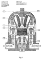
- FIG 1 a reactor according to one embodiment of the invention is described.
- the heating occurs using a burner between the two compartments.
- the cold gas is introduced via cold gas inlet (1) and the gas is preheated in section (2) by heat exchange (7) with nested ball chain (3).
- the preheated gas is heated by gas burner (5) and flame (6).
- the hot gas passes through nested ball chain (3) where it gives off part of its heat.
- heat exchange device (8) the remainder of the heat is transferred to the entering cold gas.
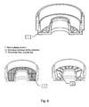
- FIG 2 details of the nested ball chain (3) and its structure (10) are given.
- the sintered metal structure is given with two possible structures and a cross-section thereof.
- the nesting ball chain may be wired in different ways, which has an influence on the contact surface (heat exchange and electrical conductivity) and the flow surface (flow rate).
- FIG 5 a reactor according to another embodiment of the invention is shown.
- the heating occurs with an electrical heater (15), and an optional coil heater (13) around the heat exchange zone (7).
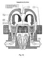
- figure 7 a reactor is shown, with the filament heater of figure 6 .
- FIG 11 a heat exchange device (18) suitable for use in the reactor of figure 10 is shown.
Landscapes
- Engineering & Computer Science (AREA)
- Environmental & Geological Engineering (AREA)
- Chemical & Material Sciences (AREA)
- Health & Medical Sciences (AREA)
- Biomedical Technology (AREA)
- Analytical Chemistry (AREA)
- General Chemical & Material Sciences (AREA)
- Oil, Petroleum & Natural Gas (AREA)
- Chemical Kinetics & Catalysis (AREA)
- Catalysts (AREA)
- Physical Or Chemical Processes And Apparatus (AREA)
- Exhaust Gas Treatment By Means Of Catalyst (AREA)
Claims (11)
- Verfahren zum Entfernen von VOC aus Gasströmen, wobei der Gasstrom durch eine erste Kammer eines Reaktors mit mehreren Kammern geleitet wird, welcher Reaktor mindestens eine erste Kammer und mindestens eine zweite Kammer umfasst, welche erste und zweite Kammern durch eine gemeinsame gasdichte Wand miteinander in einer Wärmeaustauschbeziehung sind, und in welcher ersten Kammer der Gasstrom durch Wärmeaustausch mit der zweiten Kammer erwärmt wird, der erwärmte Gasstrom zur zweiten Kammer geleitet wird, der in die zweite Kammer geleitete erwärmte Gasstrom durch Hinzufügen von zusätzlichem Brenngas oder elektrische Erwärmung weiter erwärmt wird, und das erwärmte Gas durch die zweite Kammer über einen katalytischen Oxidationskatalysator geleitet wird, um die organischen Verbindungen zu verbrennen, wobei sowohl die erste als auch die zweite Kammer mit einem porösen gesinterten Metallmaterial gefüllt sind, welches in einer Wärmeaustauschbeziehung mit der gemeinsamen Wand ist, wobei das Metallmaterial in der zweiten Kammer mit dem Oxidationskatalysator versehen ist.
- Verfahren nach Anspruch 1, wobei die weitere Erwärmung durch Einblasen eines brennbaren Gases in den Gasstrom und Entzünden dieses brennbaren Gases erfolgt, wobei das Gas vorzugsweise aus gasförmigen Kohlenwasserstoffen ausgewählt wird.
- Verfahren nach Anspruch 1 oder 2, wobei die Temperatur des Gasstroms in der zweiten Kammer zwischen 100 und 300°C beträgt.
- Verfahren nach Anspruch 1-3, wobei der Oxidationskatalysator unter Edelmetallen wie Platin, Palladium und Kombinationen davon ausgewählt wird.
- Verfahren nach Anspruch 1-4, wobei die weitere Erwärmung in einem separaten Katalysatorbett erfolgt, das am Eingang der zweiten Kammer angeordnet ist.
- Verfahren nach Anspruch 1-5, wobei der Gasstrom zur weiteren Erwärmung durch ein erwärmtes Metallgeflecht geleitet wird.
- Verfahren nach Anspruch 6, wobei das Metallgeflecht verwendet wird, um Viren, Bakterien und Staub, die in dem Gasstrom vorhanden sind, aufzufangen und aus dem Gasstrom zu entfernen.
- Verfahren nach Anspruch 7, wobei das Metallgeflecht erwärmt wird, um kohlenhaltige Rückstände aus dem Geflecht zu verbrennen, wenn der Druckabfall zu hoch geworden ist.
- Verfahren nach einem der vorhergehenden Ansprüche, wobei VOC aus dem Gasstrom entfernt werden.
- Reaktor, geeignet zur Verwendung in dem Verfahren von Anspruch 1-9, umfassend mindestens eine erste Kammer (2) und mindestens eine zweite Kammer (3), welche erste und zweite Kammern durch eine gemeinsame gasdichte Wand (7) in einer Wärmeaustauschbeziehung miteinander sind, und in welcher ersten Kammer ein Gasstrom durch Wärmeaustausch mit der zweiten Kammer erwärmt werden kann, Mittel, um den erwärmten Gasstrom von der ersten Kammer zur zweiten Kammer zu leiten und wobei Mittel (5) vorhanden sind, um den in die zweite Kammer strömenden Gasstrom entweder durch Hinzufügen von zusätzlichem brennbaren Gas oder elektrische Erwärmung weiter zu erwärmen, wobei die zweite Kammer mit einem katalytischen Oxidationskatalysator versehen ist, um die organischen Verbindungen zu verbrennen, wobei sowohl die erste als auch die zweite Kammer mit einem porösen, gesinterten Metallmaterial gefüllt sind, das in einer Wärmeaustauschbeziehung mit der gemeinsamen Wand ist, wobei die Oberfläche des Metallmaterials in der zweiten Kammer katalytisch aktiv für die Oxidation ist.
- Reaktor nach Anspruch 10, wobei ein Metallgeflecht mit Mitteln zu dessen elektrischer Erwärmung als Mittel für die weitere Erwärmung vorhanden ist.
Priority Applications (4)
| Application Number | Priority Date | Filing Date | Title |
|---|---|---|---|
| EP20090153651 EP2228122B1 (de) | 2009-02-25 | 2009-02-25 | Verfahren und Reaktor zum Entfernen von VOC aus Gasströmen |
| CN201080018080.3A CN102413903B (zh) | 2009-02-25 | 2010-02-25 | 从气流中去除有机化合物的方法和反应器 |
| PCT/NL2010/050096 WO2010098665A1 (en) | 2009-02-25 | 2010-02-25 | Process and reactor for removing organic compounds from gas flows |
| US13/203,291 US9101880B2 (en) | 2009-02-25 | 2010-02-25 | Process and reactor for removing organic compounds from gas flows |
Applications Claiming Priority (1)
| Application Number | Priority Date | Filing Date | Title |
|---|---|---|---|
| EP20090153651 EP2228122B1 (de) | 2009-02-25 | 2009-02-25 | Verfahren und Reaktor zum Entfernen von VOC aus Gasströmen |
Publications (2)
| Publication Number | Publication Date |
|---|---|
| EP2228122A1 EP2228122A1 (de) | 2010-09-15 |
| EP2228122B1 true EP2228122B1 (de) | 2012-08-15 |
Family
ID=40445469
Family Applications (1)
| Application Number | Title | Priority Date | Filing Date |
|---|---|---|---|
| EP20090153651 Active EP2228122B1 (de) | 2009-02-25 | 2009-02-25 | Verfahren und Reaktor zum Entfernen von VOC aus Gasströmen |
Country Status (4)
| Country | Link |
|---|---|
| US (1) | US9101880B2 (de) |
| EP (1) | EP2228122B1 (de) |
| CN (1) | CN102413903B (de) |
| WO (1) | WO2010098665A1 (de) |
Families Citing this family (2)
| Publication number | Priority date | Publication date | Assignee | Title |
|---|---|---|---|---|
| US11555473B2 (en) | 2018-05-29 | 2023-01-17 | Kontak LLC | Dual bladder fuel tank |
| US11638331B2 (en) | 2018-05-29 | 2023-04-25 | Kontak LLC | Multi-frequency controllers for inductive heating and associated systems and methods |
Family Cites Families (19)
| Publication number | Priority date | Publication date | Assignee | Title |
|---|---|---|---|---|
| FR1409120A (fr) * | 1964-09-25 | 1965-08-20 | Réacteur pour effectuer des réactions en phase gazeuse par catalyse hétérogène | |
| US3870474B1 (en) | 1972-11-13 | 1991-04-02 | Regenerative incinerator systems for waste gases | |
| JPS5333974A (en) * | 1976-09-10 | 1978-03-30 | Nippon Kokan Kk <Nkk> | Removing method for hydrocarbons in exhaust gas |
| US4478808A (en) | 1981-12-24 | 1984-10-23 | Institut Kataliza Sibirskogo Otdelenia Akademii Nauk Sssr | Method of producing sulphur trioxide |
| US4444735A (en) | 1982-09-15 | 1984-04-24 | The Air Preheater Company, Inc. | Thermal oxidizer and method for operating same |
| SE441623B (sv) | 1984-06-21 | 1985-10-21 | Heed Bjoern | Forfarande och anordning for forbrenning och/eller sonderdelning av fororeningar |
| DE3435319A1 (de) | 1984-09-26 | 1986-04-03 | Michael 4150 Krefeld Laumen | Katalytischer dampferzeuger |
| US4877592A (en) | 1986-10-17 | 1989-10-31 | Institut Kataliza Sibirskogo Otdelenia Akademii Nauk Sssr | Method of catalytic cleaning of exhaust gases |
| EP0397856A4 (en) * | 1988-11-23 | 1991-05-15 | Univ Alberta | Method and apparatus for purifying air |
| NL8902250A (nl) | 1989-09-08 | 1991-04-02 | Veg Gasinstituut Nv | Werkwijze voor het uitvoeren van een chemische reactie en daarbij te gebruiken reactor. |
| WO1996039243A1 (en) * | 1995-06-06 | 1996-12-12 | Amoco Corporation | Catalytic vent gas treatment system for abatement of volatile chemical emissions |
| CA2259386C (en) * | 1996-06-28 | 2002-06-25 | Matsushita Electric Works, Ltd. | Modification apparatus |
| US5997594A (en) * | 1996-10-30 | 1999-12-07 | Northwest Power Systems, Llc | Steam reformer with internal hydrogen purification |
| NL1006638C2 (nl) | 1997-07-21 | 1999-01-25 | Univ Utrecht | Dunne keramische deklagen. |
| NL1010267C2 (nl) | 1998-10-07 | 2000-04-10 | Univ Utrecht | Gemodificeerde poreuze metaal oppervlakken. |
| NL1011098C2 (nl) | 1999-01-21 | 2000-07-24 | Univ Utrecht | Keramische deklaag. |
| DE10213891B4 (de) * | 2002-03-28 | 2014-02-27 | Robert Bosch Gmbh | Vorrichtung zur Umformung eines kohlenwasserstoffhaltigen Stoffstroms |
| US8216323B2 (en) * | 2005-06-30 | 2012-07-10 | General Electric Company | System and method for hydrogen production |
| US20090010801A1 (en) * | 2007-05-15 | 2009-01-08 | Murphy Oliver J | Air cleaner |
-
2009
- 2009-02-25 EP EP20090153651 patent/EP2228122B1/de active Active
-
2010
- 2010-02-25 CN CN201080018080.3A patent/CN102413903B/zh active Active
- 2010-02-25 US US13/203,291 patent/US9101880B2/en active Active
- 2010-02-25 WO PCT/NL2010/050096 patent/WO2010098665A1/en not_active Ceased
Also Published As
| Publication number | Publication date |
|---|---|
| US20120039781A1 (en) | 2012-02-16 |
| EP2228122A1 (de) | 2010-09-15 |
| CN102413903A (zh) | 2012-04-11 |
| WO2010098665A1 (en) | 2010-09-02 |
| CN102413903B (zh) | 2015-01-14 |
| US9101880B2 (en) | 2015-08-11 |
Similar Documents
| Publication | Publication Date | Title |
|---|---|---|
| JP4990267B2 (ja) | アンモニアに基づく水素発生装置及びその使用方法 | |
| EP1534428B1 (de) | Methanol-wasserdampf-reformierungskatalysatoren, wasserdampfreformer und diese enthaltende brennstoffzellensysteme | |
| KR101738610B1 (ko) | 온도조절-화학적 기상 증착법을 이용한 다공성 담체에 금속 산화물이 담지된 촉매의 제조방법 | |
| US7410931B2 (en) | Thermal regulating catalyst composition | |
| US20130125462A1 (en) | Chemical looping system | |
| JP2000302410A (ja) | 水素精製装置 | |
| US20100284892A1 (en) | Process For The Purification Of A Carbon Dioxide Stream With Heating Value And Use Of This Process In Hydrogen Producing Processes | |
| CN101878285B (zh) | 可燃气体处理系统和可燃气体处理方法 | |
| US20090224209A1 (en) | Process to prepare a mixture of hydrogen and carbon monoxide | |
| JPWO2009157434A1 (ja) | 二酸化炭素オフガスの浄化方法および浄化用燃焼触媒、並びに天然ガスの製造方法 | |
| EP4466221A1 (de) | Verfahren zur durchführung einer ammoniak-crackreaktion in einem wirbelschichtreaktor | |
| US9101880B2 (en) | Process and reactor for removing organic compounds from gas flows | |
| KR20120050908A (ko) | 수소 가스 제조 장치 | |
| US9364791B1 (en) | Carbon dioxide decomposition | |
| Kuhn et al. | Selective Reduction of Oxygen on Non‐Noble Metal Copper Nanocatalysts | |
| KR20250109958A (ko) | Co 및 voc 산화반응 촉매와 이의 제조방법 | |
| AU2021314836B2 (en) | Process to conduct an endothermic steam reforming reaction in a fluidized bed reactor | |
| CN100483825C (zh) | 转换反应器、使用其的燃料电池系统及该反应器运行方法 | |
| JP4056773B2 (ja) | 水素生成装置および燃料電池発電システム | |
| US7625482B1 (en) | Nanoparticulate-catalyzed oxygen transfer processes | |
| JP2024521178A (ja) | 触媒活性を有する電気ヒーター | |
| JP2026027768A (ja) | 燃焼式アンモニア分解装置および燃焼式アンモニア分解方法 | |
| Kwon et al. | Catalytic Oxidation of CO and CH4 as Well as Mixture of CO and CH4 with Nano and Micro Fe2O3 | |
| JP5187845B2 (ja) | メタノール分解触媒 | |
| JP2026027770A (ja) | 燃焼式アンモニア分解装置および燃焼式アンモニア分解方法 |
Legal Events
| Date | Code | Title | Description |
|---|---|---|---|
| PUAI | Public reference made under article 153(3) epc to a published international application that has entered the european phase |
Free format text: ORIGINAL CODE: 0009012 |
|
| AK | Designated contracting states |
Kind code of ref document: A1 Designated state(s): AT BE BG CH CY CZ DE DK EE ES FI FR GB GR HR HU IE IS IT LI LT LU LV MC MK MT NL NO PL PT RO SE SI SK TR |
|
| AX | Request for extension of the european patent |
Extension state: AL BA RS |
|
| 17P | Request for examination filed |
Effective date: 20110307 |
|
| 17Q | First examination report despatched |
Effective date: 20110330 |
|
| AKX | Designation fees paid |
Designated state(s): AT BE BG CH CY CZ DE DK EE ES FI FR GB GR HR HU IE IS IT LI LT LU LV MC MK MT NL NO PL PT RO SE SI SK TR |
|
| GRAP | Despatch of communication of intention to grant a patent |
Free format text: ORIGINAL CODE: EPIDOSNIGR1 |
|
| RTI1 | Title (correction) |
Free format text: PROCESS AND REACTOR FOR REMOVINGVOC FROM GAS FLOWS |
|
| GRAS | Grant fee paid |
Free format text: ORIGINAL CODE: EPIDOSNIGR3 |
|
| GRAA | (expected) grant |
Free format text: ORIGINAL CODE: 0009210 |
|
| AK | Designated contracting states |
Kind code of ref document: B1 Designated state(s): AT BE BG CH CY CZ DE DK EE ES FI FR GB GR HR HU IE IS IT LI LT LU LV MC MK MT NL NO PL PT RO SE SI SK TR |
|
| REG | Reference to a national code |
Ref country code: GB Ref legal event code: FG4D Ref country code: CH Ref legal event code: EP Ref country code: AT Ref legal event code: REF Ref document number: 570507 Country of ref document: AT Kind code of ref document: T Effective date: 20120815 |
|
| REG | Reference to a national code |
Ref country code: IE Ref legal event code: FG4D |
|
| REG | Reference to a national code |
Ref country code: DE Ref legal event code: R096 Ref document number: 602009008926 Country of ref document: DE Effective date: 20121011 |
|
| REG | Reference to a national code |
Ref country code: NL Ref legal event code: T3 |
|
| REG | Reference to a national code |
Ref country code: AT Ref legal event code: MK05 Ref document number: 570507 Country of ref document: AT Kind code of ref document: T Effective date: 20120815 |
|
| PG25 | Lapsed in a contracting state [announced via postgrant information from national office to epo] |
Ref country code: HR Free format text: LAPSE BECAUSE OF FAILURE TO SUBMIT A TRANSLATION OF THE DESCRIPTION OR TO PAY THE FEE WITHIN THE PRESCRIBED TIME-LIMIT Effective date: 20120815 Ref country code: IS Free format text: LAPSE BECAUSE OF FAILURE TO SUBMIT A TRANSLATION OF THE DESCRIPTION OR TO PAY THE FEE WITHIN THE PRESCRIBED TIME-LIMIT Effective date: 20121215 Ref country code: FI Free format text: LAPSE BECAUSE OF FAILURE TO SUBMIT A TRANSLATION OF THE DESCRIPTION OR TO PAY THE FEE WITHIN THE PRESCRIBED TIME-LIMIT Effective date: 20120815 Ref country code: LT Free format text: LAPSE BECAUSE OF FAILURE TO SUBMIT A TRANSLATION OF THE DESCRIPTION OR TO PAY THE FEE WITHIN THE PRESCRIBED TIME-LIMIT Effective date: 20120815 Ref country code: AT Free format text: LAPSE BECAUSE OF FAILURE TO SUBMIT A TRANSLATION OF THE DESCRIPTION OR TO PAY THE FEE WITHIN THE PRESCRIBED TIME-LIMIT Effective date: 20120815 Ref country code: NO Free format text: LAPSE BECAUSE OF FAILURE TO SUBMIT A TRANSLATION OF THE DESCRIPTION OR TO PAY THE FEE WITHIN THE PRESCRIBED TIME-LIMIT Effective date: 20121115 |
|
| PG25 | Lapsed in a contracting state [announced via postgrant information from national office to epo] |
Ref country code: BE Free format text: LAPSE BECAUSE OF FAILURE TO SUBMIT A TRANSLATION OF THE DESCRIPTION OR TO PAY THE FEE WITHIN THE PRESCRIBED TIME-LIMIT Effective date: 20120815 Ref country code: PL Free format text: LAPSE BECAUSE OF FAILURE TO SUBMIT A TRANSLATION OF THE DESCRIPTION OR TO PAY THE FEE WITHIN THE PRESCRIBED TIME-LIMIT Effective date: 20120815 Ref country code: PT Free format text: LAPSE BECAUSE OF FAILURE TO SUBMIT A TRANSLATION OF THE DESCRIPTION OR TO PAY THE FEE WITHIN THE PRESCRIBED TIME-LIMIT Effective date: 20121217 Ref country code: SI Free format text: LAPSE BECAUSE OF FAILURE TO SUBMIT A TRANSLATION OF THE DESCRIPTION OR TO PAY THE FEE WITHIN THE PRESCRIBED TIME-LIMIT Effective date: 20120815 Ref country code: SE Free format text: LAPSE BECAUSE OF FAILURE TO SUBMIT A TRANSLATION OF THE DESCRIPTION OR TO PAY THE FEE WITHIN THE PRESCRIBED TIME-LIMIT Effective date: 20120815 Ref country code: GR Free format text: LAPSE BECAUSE OF FAILURE TO SUBMIT A TRANSLATION OF THE DESCRIPTION OR TO PAY THE FEE WITHIN THE PRESCRIBED TIME-LIMIT Effective date: 20121116 Ref country code: LV Free format text: LAPSE BECAUSE OF FAILURE TO SUBMIT A TRANSLATION OF THE DESCRIPTION OR TO PAY THE FEE WITHIN THE PRESCRIBED TIME-LIMIT Effective date: 20120815 |
|
| PG25 | Lapsed in a contracting state [announced via postgrant information from national office to epo] |
Ref country code: DK Free format text: LAPSE BECAUSE OF FAILURE TO SUBMIT A TRANSLATION OF THE DESCRIPTION OR TO PAY THE FEE WITHIN THE PRESCRIBED TIME-LIMIT Effective date: 20120815 Ref country code: RO Free format text: LAPSE BECAUSE OF FAILURE TO SUBMIT A TRANSLATION OF THE DESCRIPTION OR TO PAY THE FEE WITHIN THE PRESCRIBED TIME-LIMIT Effective date: 20120815 Ref country code: CZ Free format text: LAPSE BECAUSE OF FAILURE TO SUBMIT A TRANSLATION OF THE DESCRIPTION OR TO PAY THE FEE WITHIN THE PRESCRIBED TIME-LIMIT Effective date: 20120815 Ref country code: EE Free format text: LAPSE BECAUSE OF FAILURE TO SUBMIT A TRANSLATION OF THE DESCRIPTION OR TO PAY THE FEE WITHIN THE PRESCRIBED TIME-LIMIT Effective date: 20120815 Ref country code: ES Free format text: LAPSE BECAUSE OF FAILURE TO SUBMIT A TRANSLATION OF THE DESCRIPTION OR TO PAY THE FEE WITHIN THE PRESCRIBED TIME-LIMIT Effective date: 20121126 |
|
| PG25 | Lapsed in a contracting state [announced via postgrant information from national office to epo] |
Ref country code: IT Free format text: LAPSE BECAUSE OF FAILURE TO SUBMIT A TRANSLATION OF THE DESCRIPTION OR TO PAY THE FEE WITHIN THE PRESCRIBED TIME-LIMIT Effective date: 20120815 Ref country code: SK Free format text: LAPSE BECAUSE OF FAILURE TO SUBMIT A TRANSLATION OF THE DESCRIPTION OR TO PAY THE FEE WITHIN THE PRESCRIBED TIME-LIMIT Effective date: 20120815 |
|
| PLBE | No opposition filed within time limit |
Free format text: ORIGINAL CODE: 0009261 |
|
| STAA | Information on the status of an ep patent application or granted ep patent |
Free format text: STATUS: NO OPPOSITION FILED WITHIN TIME LIMIT |
|
| 26N | No opposition filed |
Effective date: 20130516 |
|
| PG25 | Lapsed in a contracting state [announced via postgrant information from national office to epo] |
Ref country code: BG Free format text: LAPSE BECAUSE OF FAILURE TO SUBMIT A TRANSLATION OF THE DESCRIPTION OR TO PAY THE FEE WITHIN THE PRESCRIBED TIME-LIMIT Effective date: 20121115 |
|
| REG | Reference to a national code |
Ref country code: DE Ref legal event code: R097 Ref document number: 602009008926 Country of ref document: DE Effective date: 20130516 |
|
| PG25 | Lapsed in a contracting state [announced via postgrant information from national office to epo] |
Ref country code: MC Free format text: LAPSE BECAUSE OF NON-PAYMENT OF DUE FEES Effective date: 20130228 |
|
| REG | Reference to a national code |
Ref country code: CH Ref legal event code: PL |
|
| PG25 | Lapsed in a contracting state [announced via postgrant information from national office to epo] |
Ref country code: LI Free format text: LAPSE BECAUSE OF NON-PAYMENT OF DUE FEES Effective date: 20130228 Ref country code: CH Free format text: LAPSE BECAUSE OF NON-PAYMENT OF DUE FEES Effective date: 20130228 |
|
| REG | Reference to a national code |
Ref country code: FR Ref legal event code: ST Effective date: 20131031 |
|
| PG25 | Lapsed in a contracting state [announced via postgrant information from national office to epo] |
Ref country code: CY Free format text: LAPSE BECAUSE OF FAILURE TO SUBMIT A TRANSLATION OF THE DESCRIPTION OR TO PAY THE FEE WITHIN THE PRESCRIBED TIME-LIMIT Effective date: 20120815 |
|
| REG | Reference to a national code |
Ref country code: IE Ref legal event code: MM4A |
|
| PG25 | Lapsed in a contracting state [announced via postgrant information from national office to epo] |
Ref country code: IE Free format text: LAPSE BECAUSE OF NON-PAYMENT OF DUE FEES Effective date: 20130225 Ref country code: FR Free format text: LAPSE BECAUSE OF NON-PAYMENT OF DUE FEES Effective date: 20130228 |
|
| PG25 | Lapsed in a contracting state [announced via postgrant information from national office to epo] |
Ref country code: MT Free format text: LAPSE BECAUSE OF FAILURE TO SUBMIT A TRANSLATION OF THE DESCRIPTION OR TO PAY THE FEE WITHIN THE PRESCRIBED TIME-LIMIT Effective date: 20120815 |
|
| PG25 | Lapsed in a contracting state [announced via postgrant information from national office to epo] |
Ref country code: TR Free format text: LAPSE BECAUSE OF FAILURE TO SUBMIT A TRANSLATION OF THE DESCRIPTION OR TO PAY THE FEE WITHIN THE PRESCRIBED TIME-LIMIT Effective date: 20120815 |
|
| PG25 | Lapsed in a contracting state [announced via postgrant information from national office to epo] |
Ref country code: MK Free format text: LAPSE BECAUSE OF FAILURE TO SUBMIT A TRANSLATION OF THE DESCRIPTION OR TO PAY THE FEE WITHIN THE PRESCRIBED TIME-LIMIT Effective date: 20120815 Ref country code: HU Free format text: LAPSE BECAUSE OF FAILURE TO SUBMIT A TRANSLATION OF THE DESCRIPTION OR TO PAY THE FEE WITHIN THE PRESCRIBED TIME-LIMIT; INVALID AB INITIO Effective date: 20090225 Ref country code: LU Free format text: LAPSE BECAUSE OF NON-PAYMENT OF DUE FEES Effective date: 20130225 |
|
| REG | Reference to a national code |
Ref country code: DE Ref legal event code: R081 Ref document number: 602009008926 Country of ref document: DE Owner name: EVERS MANAGEMENT B.V., NL Free format text: FORMER OWNER: K.M.W.E. MANAGEMENT B.V., EINDHOVEN, NL Ref country code: DE Ref legal event code: R082 Ref document number: 602009008926 Country of ref document: DE Representative=s name: VEREENIGDE OCTROOIBUREAUX V.O., DE Ref country code: DE Ref legal event code: R081 Ref document number: 602009008926 Country of ref document: DE Owner name: KMWE GROUP B.V., NL Free format text: FORMER OWNER: K.M.W.E. MANAGEMENT B.V., EINDHOVEN, NL |
|
| REG | Reference to a national code |
Ref country code: NL Ref legal event code: HC Owner name: KMWE NETHERLANDS B.V.; NL Free format text: DETAILS ASSIGNMENT: CHANGE OF OWNER(S), CHANGE OF OWNER(S) NAME; FORMER OWNER NAME: K.M.W.E. MANAGEMENT B.V. Effective date: 20170728 Ref country code: NL Ref legal event code: PD Owner name: KMWE GROUP B.V.; NL Free format text: DETAILS ASSIGNMENT: CHANGE OF OWNER(S), MERGE; FORMER OWNER NAME: KMWE NETHERLANDS B.V. Effective date: 20170728 |
|
| REG | Reference to a national code |
Ref country code: GB Ref legal event code: 732E Free format text: REGISTERED BETWEEN 20171012 AND 20171018 |
|
| REG | Reference to a national code |
Ref country code: NL Ref legal event code: PD Owner name: EVERS MANAGEMENT B.V.; NL Free format text: DETAILS ASSIGNMENT: CHANGE OF OWNER(S), ASSIGNMENT; FORMER OWNER NAME: KMWE NETHERLANDS B.V. Effective date: 20190815 |
|
| REG | Reference to a national code |
Ref country code: DE Ref legal event code: R082 Ref document number: 602009008926 Country of ref document: DE Representative=s name: VEREENIGDE OCTROOIBUREAUX V.O., DE Ref country code: DE Ref legal event code: R081 Ref document number: 602009008926 Country of ref document: DE Owner name: EVERS MANAGEMENT B.V., NL Free format text: FORMER OWNER: KMWE GROUP B.V., EINDHOVEN, NL |
|
| REG | Reference to a national code |
Ref country code: GB Ref legal event code: 732E Free format text: REGISTERED BETWEEN 20190926 AND 20191002 |
|
| PGFP | Annual fee paid to national office [announced via postgrant information from national office to epo] |
Ref country code: NL Payment date: 20250225 Year of fee payment: 17 |
|
| PGFP | Annual fee paid to national office [announced via postgrant information from national office to epo] |
Ref country code: DE Payment date: 20250227 Year of fee payment: 17 |
|
| PGFP | Annual fee paid to national office [announced via postgrant information from national office to epo] |
Ref country code: GB Payment date: 20250227 Year of fee payment: 17 |