EP2228124A1 - Appareil de séparation sur film de type à immersion et cartouche de film - Google Patents
Appareil de séparation sur film de type à immersion et cartouche de film Download PDFInfo
- Publication number
- EP2228124A1 EP2228124A1 EP08853823A EP08853823A EP2228124A1 EP 2228124 A1 EP2228124 A1 EP 2228124A1 EP 08853823 A EP08853823 A EP 08853823A EP 08853823 A EP08853823 A EP 08853823A EP 2228124 A1 EP2228124 A1 EP 2228124A1
- Authority
- EP
- European Patent Office
- Prior art keywords
- membrane
- membrane cartridge
- water intake
- cartridge
- filtration
- Prior art date
- Legal status (The legal status is an assumption and is not a legal conclusion. Google has not performed a legal analysis and makes no representation as to the accuracy of the status listed.)
- Granted
Links
Images


Classifications
-
- B—PERFORMING OPERATIONS; TRANSPORTING
- B01—PHYSICAL OR CHEMICAL PROCESSES OR APPARATUS IN GENERAL
- B01D—SEPARATION
- B01D61/00—Processes of separation using semi-permeable membranes, e.g. dialysis, osmosis or ultrafiltration; Apparatus, accessories or auxiliary operations specially adapted therefor
- B01D61/14—Ultrafiltration; Microfiltration
- B01D61/18—Apparatus therefor
-
- B—PERFORMING OPERATIONS; TRANSPORTING
- B01—PHYSICAL OR CHEMICAL PROCESSES OR APPARATUS IN GENERAL
- B01D—SEPARATION
- B01D63/00—Apparatus in general for separation processes using semi-permeable membranes
- B01D63/08—Flat membrane modules
- B01D63/082—Flat membrane modules comprising a stack of flat membranes
- B01D63/0821—Membrane plate arrangements for submerged operation
-
- B—PERFORMING OPERATIONS; TRANSPORTING
- B01—PHYSICAL OR CHEMICAL PROCESSES OR APPARATUS IN GENERAL
- B01D—SEPARATION
- B01D63/00—Apparatus in general for separation processes using semi-permeable membranes
- B01D63/08—Flat membrane modules
- B01D63/082—Flat membrane modules comprising a stack of flat membranes
- B01D63/0822—Plate-and-frame devices
-
- B—PERFORMING OPERATIONS; TRANSPORTING
- B01—PHYSICAL OR CHEMICAL PROCESSES OR APPARATUS IN GENERAL
- B01D—SEPARATION
- B01D65/00—Accessories or auxiliary operations, in general, for separation processes or apparatus using semi-permeable membranes
- B01D65/02—Membrane cleaning or sterilisation ; Membrane regeneration
- B01D65/025—Removal of membrane elements before washing
-
- B—PERFORMING OPERATIONS; TRANSPORTING
- B01—PHYSICAL OR CHEMICAL PROCESSES OR APPARATUS IN GENERAL
- B01D—SEPARATION
- B01D2313/00—Details relating to membrane modules or apparatus
- B01D2313/02—Specific tightening or locking mechanisms
-
- B—PERFORMING OPERATIONS; TRANSPORTING
- B01—PHYSICAL OR CHEMICAL PROCESSES OR APPARATUS IN GENERAL
- B01D—SEPARATION
- B01D2313/00—Details relating to membrane modules or apparatus
- B01D2313/06—External membrane module supporting or fixing means
-
- B—PERFORMING OPERATIONS; TRANSPORTING
- B01—PHYSICAL OR CHEMICAL PROCESSES OR APPARATUS IN GENERAL
- B01D—SEPARATION
- B01D2313/00—Details relating to membrane modules or apparatus
- B01D2313/56—Specific mechanisms for loading the membrane in a module
-
- B—PERFORMING OPERATIONS; TRANSPORTING
- B01—PHYSICAL OR CHEMICAL PROCESSES OR APPARATUS IN GENERAL
- B01D—SEPARATION
- B01D2315/00—Details relating to the membrane module operation
- B01D2315/06—Submerged-type; Immersion type
-
- B—PERFORMING OPERATIONS; TRANSPORTING
- B01—PHYSICAL OR CHEMICAL PROCESSES OR APPARATUS IN GENERAL
- B01D—SEPARATION
- B01D2321/00—Details relating to membrane cleaning, regeneration, sterilization or to the prevention of fouling
- B01D2321/02—Forward flushing
Definitions
- the present invention relates to a submerged membrane separator submerged and arranged, for example, in a treatment tank filled with a liquid to be treated and a membrane cartridge provided in such a submerged membrane separator.
- a submerged membrane separator 1 includes a box-type casing 2 opened at the top and the bottom, a plurality of vertically elongated membrane cartridges 3 arrayed in parallel to one another in the casing 2, and an air diffuser 4 provided below the membrane cartridges 3.
- Water intake nozzles 6 for sucking treated water 5 obtained by membrane filtration are provided on the upper end sides of the membrane cartridges 3.
- a plurality of slits 12 elongated in the up-down direction are formed on the left and right inner side surfaces of the casing 2.
- the membrane cartridges 3 are held in the casing 2 at predetermined intervals with both sides of the membrane cartridges being inserted into the slits 12 from above.
- Water collecting pipes 8 for collecting the treated water 5 are provided on one side of an upper opening 7 of the casing 2.
- the water collecting pipes 8 and the water intake nozzles 6 of the membrane cartridges 3 are connected via connection pipes 9.
- a lead-out pipe 15 for leading out the treated water 5 is connected to the water collecting pipes 8.
- a suction pump (not shown) that generates a suction force for sucking the treated water 5 is provided in the lead-out pipe 15.
- a suction force may be generated by using a water head pressure of a liquid to be treated in a treatment tank as a filtration driving pressure without using the suction pump.
- upflow 13 is caused between the membrane cartridges 3 by bubbles of air diffused from the air diffuser 4. The matter adhering to the membrane surfaces of the membrane cartridges 3 is removed by this upflow 13.
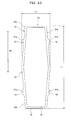
- the membrane cartridge 3 Since the air is diffused from under the membrane cartridge 3, the longer the filtration membrane 10 becomes in the top-down direction, the more effectively the air diffusion can be used. As a result, it is desirable to form the membrane cartridge 3 in an elongated shape (a rectangle) as shown in FIG. 28 .
- the submerged membrane separator 1 having the above-described configuration is described in, for example, Japanese Patent Application Laid-Open No. 2001-87763 .
- the flow rate of the upflow 13 caused by the air diffuser 4 suddenly falls in a position close to an inner side surface 2a of the casing 2. Therefore, as shown in FIG. 30 , the matter adhering to both sides of the filtration membrane 10 is hardly removed compared with the matter adhering to the center of the filtration membrane 10.
- the sludge 14 clogs a space between the sides of the filtration membranes 10 of the membrane cartridges 3 adjacent to one another.
- a clogging portion E of the sludge 14 is caused substantially over the entire length in the up-down direction on both sides of the filtration membrane 10.
- a width W of the clogging portion E of the sludge 14 is extremely small compared with a length L of the clogging portion E.
- the sludge 14 in the clogging portion E puts up a resistance when the membrane cartridge 3 is pulled out.
- a direction F in which the membrane cartridge 3 is pulled out is the same as the direction of the length L of the clogging portion E of the sludge 14. Therefore, when the membrane cartridge 3 is pulled out over the length L of the clogging portion E of the sludge 14, a great deal of resistance for shearing the sludge 14 over the length L occurs and a large amount of labor is disadvantageously required for pulling out the membrane cartridge 3.
- the membrane cartridge 3 is pulled out to above the casing 2 or the membrane cartridge 3 is inserted into the casing 2 from above the casing 2. Therefore, a space above the casing 2 needs to be secured high, and work in a high place disadvantageously involves risks.
- the water intake nozzle 6 is provided on the upper end side of the membrane cartridge 3, the connection pipe 9 is located above the membrane cartridge 3, and the upflow 13 hits the connection pipe 9 and is hindered, so that matter adhering to the membrane cartridge 3 is insufficiently removed. Further, since the upflow 13 hits the connection pipe 9 and the connection pipe 9 vibrates, it is likely that the periphery of the water intake nozzle 6 cracks.
- the liquid (treated water) permeating through the filtration membrane 10 and flowing into the inner side of the membrane cartridge 3 is sucked from the water intake nozzle 6 and collected in the water collecting pipe 8.
- the membrane cartridge 3 since the air is diffused from under the membrane cartridge 3, it is desirable to form the membrane cartridge 3 in a vertically elongated shape (a rectangle) in order to effectively use the air diffusion, as shown in FIG. 28 .
- the water intake nozzles 6 are provided on the upper end side and the lower end side of the membrane cartridge 3. Even in this case, the upflow 13 hits the connection pipe 9 connected to the water intake nozzle 6 on the upper end side of the membrane cartridge 3 and the connection pipe 9 connected to the water intake nozzle 6 on the lower end side of the membrane cartridge 3 and is hindered, and matter adhering to the membrane cartridge 3 is insufficiently removed.
- Japanese Patent Application Laid-Open No. 2000-42376 discloses a submerged membrane separator in which a plurality of water intake nozzles are provided in a membrane cartridge, only the upward water intake nozzles out of the water intake nozzles are opened and used, and the other water intake nozzles are closed and not used. Even in this case, since only the water intake nozzles on the upper end side of the membrane cartridge are used during the filtration operation, similarly to the above description, a sufficient suction pressure does not act on the lower part of the membrane cartridge, and depending on the shape of the membrane cartridge, it is disadvantageously difficult to obtain permeate using an overall filtration membrane effectively.
- a first invention is a submerged membrane separator including:
- the clogging portion of the sludge occurs substantially over the entire length in the one direction on both sides of the membrane cartridge.
- the width in the other direction of the clogging portion of the sludge is extremely small compared with the length in the one direction of the clogging portion of the sludge.
- the membrane cartridge When the membrane cartridge is removed in maintenance, the membrane cartridge is removed from the other direction substantially orthogonal to the flow in the one direction and substantially orthogonal to the arrangement direction of the membrane cartridges.
- the direction in which the membrane cartridge is removed is the same direction as the width direction of the clogging portion of the sludge rather than the length direction of the clogging portion of the sludge, unlike in the prior art. Therefore, resistance in pulling out of the membrane cartridge is generated over the width of the clogging portion of the sludge.
- the width of the clogging portion of the sludge is extremely small compared with the length of the clogging portion as explained above, at a time when the membrane cartridge is pulled out by the width of the clogging portion of the sludge, the sludge in the clogging portion is sheared and smashed. Consequently, compared with the prior art, it is possibly to reduce labor required for removing the membrane cartridge.
- a second invention is the submerged membrane separator, wherein the membrane cartridge is detachably provided in a casing opened at the top, an air diffuser for generating upflow along the membrane surface of the membrane cartridge is provided below the membrane cartridge, and the membrane cartridge can be attached and detached from a sideward direction orthogonal to the upflow.
- the clogging portion of the sludge occurs substantially over the entire length in the up-down direction on both sides of the membrane cartridge.
- the width in the sideward direction of the clogging portion of the sludge is extremely small compared with the length in the up-down direction of the clogging portion of the sludge.
- the membrane cartridge When the membrane cartridge is removed from the inside of the casing in maintenance or the like, the membrane cartridge is removed from the sideward direction, so that the direction in which the membrane cartridge is removed is the same direction as the width direction of the clogging portion of the sludge rather than the length direction of the clogging portion of the sludge, unlike in the prior art. Therefore, resistance in removing of the membrane cartridge is generated over the width of the clogging potion of the sludge.
- the width of the clogging portion of the sludge is extremely small compared with the length of the clogging portion, at a time when the membrane cartridge is pulled out by the width of the clogging portion of the sludge, the sludge in the clogging portion is sheared and smashed.
- a space above the submerged membrane separator is unnecessary. It is possible to reduce dangerous work in a high place and safety is improved.
- a third invention is the submerged membrane separator, wherein a guiding member having a comb-tooth shape for guiding the membrane cartridge in an inserting and removing direction is provided in the lower part of the casing.
- a fourth invention is the submerged membrane separator, wherein a guiding member having a comb-tooth shape for guiding the membrane cartridge in a removing and inserting direction is provided in the upper part of the casing.
- a fifth invention is the submerged membrane separator, wherein a side opening through which the membrane cartridge can be inserted and removed and an openable and closable or detachable side panel for covering the side opening are provided on the side of the casing.
- a sixth invention is the submerged membrane separator, wherein a space maintaining member for maintaining a space between the membrane cartridges is disposed on the side of the membrane cartridge.
- a seventh invention is the submerged membrane separator, wherein a water intake portion for sucking treated water obtained by membrane filtration is provided on the side of the membrane cartridge substantially orthogonal to another direction.
- An eighth invention is an elongated membrane cartridge having a filtration membrane arranged on the surface, the membrane cartridge including a plurality of water intake nozzles provided on a side thereof for sucking treated water obtained by membrane filtration, wherein heights from a lower side to the water intake nozzles are different from one another.
- a ninth invention is the membrane cartridge, wherein a plurality of water intake nozzles are provided on one side of the membrane cartridge.
- a tenth invention is the membrane cartridge, wherein a difference in height between the water intake nozzles is equal to or larger than a length in the sideward direction of the membrane cartridge.
- the difference in height between the water intake nozzles is set equal to or larger than the length in the sideward direction of the membrane cartridge. Consequently, it is possible to considerably reduce the overlap (interference) of the areas where permeate can be obtained from the filtration membrane by the respective water intake nozzles and to substantially draw out the ability of the membrane cartridge.
- An eleventh invention is a submerged membrane separator including the membrane cartridge according to any one of the eighth to tenth inventions, the submerged membrane separator including:
- the membrane cartridge since the membrane cartridge has an elongated shape, it is possible to effectively use air diffused from the air diffuser.
- the membrane cartridge When the membrane cartridge is removed from the casing and replaced or maintained and inspected, the membrane cartridge may be removed in the sideward direction from the inside of the casing or inserted into the inside of the casing from the sideward direction. In this case, since the water intake nozzles are provided on the side of the membrane cartridge, the water intake nozzles do not obstruct the removal and insertion of the membrane cartridge.
- a direction in which the membrane cartridge is removed is the same direction as the width direction of the clogging portion of sludge rather than the length direction of the clogging portion of the sludge, unlike in the prior art. Therefore, resistance in pulling out of the membrane cartridge occurs over the width of the clogging portion of the sludge.
- the width of the clogging portion of the sludge is extremely small compared with the length of the clogging portion, it is possible to reduce labor required for removing the membrane cartridge compared with the prior art.
- a space above the submerged membrane separator is unnecessary. It is possible to reduce dangerous work in a high place and safety is improved. It is possible to easily remove and insert the membrane cartridge from the sideward direction of a frame body through the side opening. During the filtration operation, it is possible to prevent bubbles of air diffused from the air diffuser from being released to the outside of the casing through the side opening by closing the side opening.
- the plurality of water intake nozzles are provided on the side of the membrane cartridge and located at different heights. Therefore, a sufficient suction pressure acts entirely over the membrane cartridge. Consequently, it is possible to obtain treated water (permeate) using the entire filtration membrane effectively.
- the membrane cartridge when the membrane cartridge is inserted into and removed from the inside of the casing from the sideward direction, the water intake nozzles do not obstruct the removal and insertion of the membrane cartridge. Consequently, it is possible to smoothly perform work such as replacement and maintenance and inspection of the membrane cartridge.
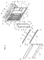
- reference numeral 31 denotes a submerged membrane separator.
- This submerged membrane separator 31 is submerged in a treatment tank 32 and separates activated sludge and treated water.
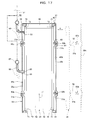
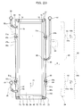
- the submerged membrane separator 31 includes a box-type casing 33 for membranes opened at the top and the bottom, a plurality of flat membrane cartridges 34 arrayed in parallel and opposed to one another in this casing 33, and an air diffuser 36 provided below these membrane cartridges 34.
- the air diffuser 36 is an example of a flow generating device for diffusing air from a plurality of diffusing holes formed in an air diffusion pipe to thereby generate upflow 77 along the membrane surface of the membrane cartridge 34 (an example of a flow in one direction).
- the casing 33 for membranes includes a frame body 37, a pair of front and rear end covers 38 for covering both front and rear ends of the frame body 37 in an arrangement direction C of the membrane cartridges 34, and a pair of left and right side panels 39a and 39b detachably attached to both left and right sides of the frame body 37.
- the side panels 39a and 39b are an example of wall members and located on both sides of a channel for the upflow 77 formed between the membrane cartridges 34 adjacent to each other.
- the frame body 37 includes a bottom frame 41 having a square frame shape, an upper frame 42 having a square frame shape, and a plurality of vertical frames 43a and 43b coupled between four corners of the frames 41 and 42.
- the width direction A is an example of the sideward direction (the other direction) orthogonal to the upflow 77 and orthogonal to the arrangement direction C of the membrane cartridges 34.
- the one side panel 39a is attached to the frame body 37 by a plurality of bolts 46 and closes the one side opening 45a.
- the other side panel 39b is attached to the frame body 37 by a plurality of bolts 46 and closes the other side opening 45b.
- the bolts 46 are removed and the one side panel 39a is removed from the frame body 37, the one side opening 45a is opened.
- the other side opening 45b is opened.
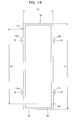
- Etch of the membrane cartridges 34 includes a flat filtration plate 49 having a rectangular shape elongated in the up-down direction, filtration membranes 50 attached to both front and rear sides of the filtration plate 49, and a plurality of supporting portions 51a and 51b provided on both sides of the filtration plate 49.
- the supporting portions 51a and 51b are provided vertically in pairs on both sides of the filtration plate 49 in the width direction A and project to the outer side.
- Recesses 52 having a square shape are formed in the supporting portions 51a and 51b.
- Water intake nozzles 53 (an example of water intake portions) for sucking treated water obtained by the filtration membranes 50 are provided at upper ends on both sides orthogonal to the width direction A (the other direction) of the filtration plate 49.
- Permeate channels (not shown) communicating with the water intake nozzles 53 are respectively formed on both front and rear sides of the filtration plate 49. The permeate channels are covered with the filtration membranes 50.
- a pair of left and right water collecting pipes 55 for collecting treated water sucked from the water intake nozzles 53 of the membrane cartridges 34 are provided in the front-rear direction on the outer sides on the left and right of the upper frame 42 of the frame body 37.
- the water collecting pipes 55 and the water intake nozzles 53 are connected via connection pipes 56 having flexibility.
- a lead-out pipe 57 for leading out the treated water is connected to the water collecting pipes 55.
- a suction pump (not shown) for generating a suction force for sucking the treated water is provided in the lead-out pipe 57.
- a suction force may be generated by using the head pressure of water to be treated 35 in the treatment tank 32 as a filtration driving pressure without using the suction pump.
- the peripheral portions of the filtration membranes 50 are welded to the filtration plate 49 by ultrasound or the like, whereby the filtration membranes 50 are attached to the filtration plate 49.
- Welded portions 59 of the filtration membranes 50 and the filtration plate 49 are formed over the entire periphery along the peripheral portions of the filtration membranes 50.
- a projecting portion 60 surrounding the outer sides of the peripheral portions of the filtration membranes 50 is formed on each of the front and rear surfaces of the filtration plate 49.
- the projecting portion 60 is formed in a square frame shape by a projecting portion 60a on one side, a projecting portion 60b on the other side, an upper projecting portion 60c, and a lower projecting portion 60d.
- the projecting portion 60a on one side is formed along the outer side of left or right one side of the filtration membranes 50.
- the projecting portion 60b on the other side is formed along the outer side of the other left or right side of the filtration membranes 50.
- the upper projecting portion 60c is formed along the outer side of the upper sides of the filtration membranes 50.
- the lower projecting potion 60d is formed along the outer side of the lower sides of the filtration membranes 50.
- the projecting portion 60 has a triangular section and includes inclined surfaces 61 that are inclined in a projecting direction from the surface of the filtration plate 49 as being closer to the peripheral edges of the filtration membranes 50 from the peripheral edges of the filtration plate 49.
- a height h from the surface of the filtration plate 49 to the distal end of the projecting portion 60 is set larger than a height t (thickness) of the peripheral edges of the filtration membranes 50.
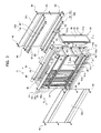
- upper guiding members 70 and lower guiding members 71 having a comb-tooth shape for guiding the membrane cartridge 34 in the width direction A (an example of a removing and inserting direction) are provided in the inside of the casing 33 for membranes.
- the upper guiding members 70 are provided horizontally in pairs in the upper frame 42 of the frame body 37.
- the lower guiding members 71 are provided horizontally in pairs in the bottom frame 41.
- a plurality of front and rear guiding grooves 72 are formed in each of the upper and lower guiding members 70 and 71.
- the upper end of the membrane cartridge 34 is freely inserted into and removed from the guiding grooves 72 of the upper guiding member 70 from the width direction A.
- the lower end of the membrane cartridge 34 is freely inserted into and removed from the guiding grooves 72 of the lower guiding member 71 from the width direction A.
- a height H1 between upper inner surfaces 70a of the guiding grooves 72 of the upper guiding member 70 and lower inner surfaces 71a of the guiding grooves 72 of the lower guiding member 71 is set slightly larger than a height H2 of the membrane cartridge 34.
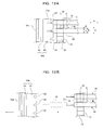
- pairs of left and right space maintaining members 63a and 63b for maintaining a space S between the membrane cartridges 34 at a predetermined space are provided vertically in two places in the casing 33 for membranes. As shown in FIGS. 8 and 9 , these space maintaining members 63a and 63b maintain the supporting portions 51a and 51b of the membrane cartridges 34 while allowing for movement in the up-down direction B.
- the space maintaining members 63a and 63b include horizontal frames 64 and holding members 65 provided in the horizontal frames 64.
- the horizontal frames 64 are angle-shaped members having vertical plate portions 64a and horizontal plate portions 64b. Both ends of the horizontal frame 64 are detachably coupled between the front and rear vertical frames 43a and 43b by bolts 66 and nuts 67.
- the material of the holding members 65 is an elastic material such as rubber. Grooves 68 are formed over the entire length on the outer surfaces of the holding members 65. A plurality of front and rear slits 69 are formed on the inner surfaces of the holding members 65. The horizontal plate portions 64b of the horizontal frames 64 are inserted into the grooves 68 of the holding members 65, whereby the holding members 65 are attached to the horizontal frames 64.
- the supporting portions 51a and 51b of the membrane cartridge 34 fit into the slits 69 of the holding member 65 in the recesses 52.
- the space S in the arrangement direction C between the membrane cartridges 34 is maintained at the predetermined space by the space maintaining members 63a and 63b.
- the recesses 52 of the supporting portions 51a and 51b are fit in and set in contact with the slits 69 of the holding member 65 in the width direction A (left-right direction), the up-down direction B, and the arrangement direction C (front-rear direction).
- the upflow 77 is generated between the membrane cartridges 34 by bubbles of air diffused from the air diffuser 36. The matter adhering to the membrane cartridges 34 is removed by the upflow 77.
- the holding members 65 of the space maintaining members 63a and 63b are deformed by receiving a force of the upflow 77 and a buoyant force acting on the membrane cartridge 34, whereby the membrane cartridge 34 is slightly buoyed up from the lower inner surface 71a of the guiding groove 72 of the lower guiding member 71 and actively vibrates in the up-down direction B and the arrangement direction C. Since the matter adhering to the membrane cartridge 34 is removed by this vibration, the cleaning effect of the membrane cartridge 34 is further improved.
- the bolts 66 are unscrewed to remove the space maintaining members 63a on one of the left and right from the frame body 37. Consequently, as shown in FIGS. 11 and 12B , the supporting portions 51a on one of the left and right of the membrane cartridge 34 disengage from the slits 69 of the space maintaining members 63a on one of the left and right. Thereafter, as indicated by the virtual lines of FIGS. 2 and 11 , the membrane cartridge 34 can be pulled out from the inside of the casing 33 for membranes in the width direction A of the membrane cartridge 34 through the one side opening 45a and taken out to the outer side of the casing 33.
- the recesses 52 of the supporting portions 51b on the other of the left and right of the membrane cartridge 34 disengage from the slits 69 of the space maintaining members 63b on the other of the left and right.
- the membrane cartridge 34 is pulled out in the width direction A while being guided by the upper and lower guiding grooves 72.
- the bolts 66 are screwed to attach the space maintaining members 63a on one of the left and right to the vertical frames 43a on one of the left and right of the frame body 37. Consequently, as shown in FIGS. 10 and 12A , the recesses 52 of the supporting portions 51a on one of the left and right of the membrane cartridges 34 are inserted into the slits 69 of the space maintaining members 63a on one of the left and right.
- the bolts 46 are screwed to attach the one side panel 39a to the frame body 37 as shown in FIGS. 10 and 12A to close the one side opening 45a.
- the membrane cartridge 34 is housed in the inside of the casing 33.
- the space S between the membrane cartridges 34 is accurately maintained at the predetermined space by the space maintaining members 63a and 63b.
- a clogging portion E of the sludge 14 occurs substantially over the entire length in the up-down direction B on both sides of the membrane cartridge 34.
- a width W in the sideward direction of the clogging portion E of the sludge 14 is extremely small compared with a length L in the up-down direction of the clogging portion E of the sledge 14.
- the direction in which the membrane cartridge 34 is removed is the same as the direction of the width W of the clogging portion E of the sludge 14 rather than the direction of the length L of the clogging portion E of the sludge 14 (see FIG. 30 ), unlike in the prior art. Therefore, resistance in pulling out of the membrane cartridge 34 is generated over the width W of the clogging portion E of the sludge 14.
- the width W of the clogging portion E of the sludge 14 is extremely small compared with the length L as explained above, at a time when the membrane cartridge 34 is pulled out by the width W, the sludge 14 in the clogging portion E is sheared and smashed.. Consequently, compared with the prior art, it is possible to reduce labor required for removing the membrane cartridge 34 from the inside of the casing 33.
- the injection nozzle 76 is opposed to the one side opening 45a and the high-pressure cleaning liquid 75 is jetted from the injection nozzle 76 to the membrane cartridges 34. Consequently, the high-pressure cleaning liquid 75 is jetted to between the membrane cartridges 34 through the one side opening 45a, the sludge 14 clogging spaces between the membrane cartridges 34 is smashed and removed, and the membrane surfaces of the membrane cartridges 34 are cleaned.
- the cleaning liquid 75 hits the projecting portion 60a on one side immediately before the left or right one side edge of the filtration membrane 50 and the direction of the cleaning liquid 75 is bent by the projecting portion 60a on one side. Therefore, it is possible to prevent the cleaning liquid 75 from directly hitting the left or right one side edge of the filtration membrane 50. Consequently, it is possible to prevent the left or right one side edge of the filtration membrane 50 from peeling off from the filtration plate 49.
- the one side panel 39a and the one space maintaining member 63a are removed from the frame body 37 to open the one side opening 45a and remove the membrane cartridge 34 from and insert the membrane cartridge 34 into the casing 33 through the one side opening 45a.
- the other side panel 39b and the other space maintaining member 63b may be removed from the frame body 37 to remove the membrane cartridge 34 from and insert the membrane cartridge 34 into the casing 33 through the other side opening 45b.
- the one side panel 39a is removed from the frame body 37 to open the one side opening 45a and jet the cleaning liquid 75 from the one side opening 45a to the spaces between the membrane cartridges 34.
- the other side panel 39b may be removed from the frame body 37 to open the other side opening 45b and jet the cleaning liquid 75 from the other side opening 45b to the spaces between the membrane cartridges 34.
- the cleaning liquid 75 hits the projecting portions 60b on the other side of the membrane cartridges 34, it is possible to prevent the cleaning liquid 75 from directly hitting the left or right other side edges of the filtration membranes 50.
- the cleaning liquid 75 may be jetted from an upper opening 40 of the casing 33 to the spaces between the membrane cartridges 34. In this case, since the cleaning liquid 75 hits the projecting portions 60c above the membrane cartridges 34, it is possible to prevent the cleaning liquid 75 from directly hitting the upper edges of the filtration membranes 50.
- the water intake nozzles 53 are provided in pairs horizontally in the membrane cartridge 34 and the water collecting pipes 55 are provided in pairs horizontally in the frame body 37.
- the left and right water intake nozzles 53 may be provided and only one of the left and right water collecting pipes 55 may be provided.
- the side panels 39a and 39b are detachably provided in the frame body 37.
- the side panels 39a and 39b may be openably and closably provided in the frame body 37.
- the air diffuser 36 is used as an example of the flow generating device, the upflow 77 is formed as an example of the flow in one direction, and the plurality of membrane cartridges 34 are arrayed in parallel at spaces S in the front-rear direction.
- the present invention is not limited to such a configuration.
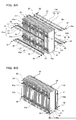
- the present invention may be a submerged membrane separator 31 in which, as shown in FIG. 13 , a rotary vane 81, is used as another example of the flow generating device, a horizontal current 82 in the front-rear direction is formed as an example of the flow in one direction, and a plurality of membrane cartridges 34 are arrayed in parallel at spaces S in the up-down direction.
- the membrane cartridges 34 are arranged in the inside of the casing 33.
- the present invention is not limited to such a configuration.
- projecting wall portions 83 may be formed on the sides of the membrane cartridges 34 and the membrane cartridges 34 may be arranged in contact with one another to use the wall portions 83 instead of the side panels 39a and 39b.
- a casing has a structure excluding the side panels 39a and 39b. The space S between the membrane cartridges 34 is maintained at a predetermined space by the wall portions 83.
- a fourth embodiment in the present invention is explained below with reference to FIGS. 15 to 17 .
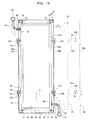
- a membrane cartridge 34 is formed in an elongated rectangle.
- a plurality of water intake nozzles 53 and 85 (an example of water intake portions) for sucking treated water obtained by a filtration membrane 50 are provided on one of both sides of a filtration plate 49 of the membrane cartridge 34 orthogonal to a width direction A.
- the first water intake nozzle 53 is located at the upper end of one side of the membrane cartridge 34 and the second water intake nozzle 85 is located between both upper and lower ends of one side thereof.
- the height from the lower side of the membrane cartridge 34 to the second water intake nozzle 85 is smaller than that from the lower side of the membrane cartridge 34 to the first water intake nozzle 53.
- a difference Hd between the heights of the first water intake nozzle 53 and the second water intake nozzle 85 is set to be equal to or larger than the length Lh in the sideward direction of the membrane cartridge 34 (i.e., Hd ⁇ Lh).
- Permeate channels 86 for communicating with the water intake nozzles 53 and 85 are respectively formed on both front and rear sides of the filtration plate 49.
- the permeate channels 86 are covered with the filtration membrane 50.
- a pair of upper and lower water collecting pipes 55 and 87 for collecting treated water sucked from the water intake nozzles 53 and 85 of the membrane cartridges 34 are provided in the front-rear direction on left or right one side of a frame body 37.
- the first water collecting pipe 55 and the first water intake nozzle 53 are connected via a first connection pipe 56 having flexibility.
- the second water collecting pipe 87 and the second water intake nozzle 85 are connected via a second connection pipe 88 having flexibility.
- a lead-out pipe 57 for leading out treated water is connected to the water collecting pipes 55 and 87.
- a suction pump (not shown) for generating a suction force for sucking the treated water is provided in the lead-out pipe 57.
- a suction force may be generated by using the head pressure of a liquid to be treated 35 in a treatment tank 32 as a filtration driving pressure without using the suction pump.
- Opened windows 89 and 90 are formed in a plurality of upper and lower places in a left or right one side panel 39a.
- the first opened window 89 is located at the upper end of the side panel 39a and opposed to the first water intake nozzle 53.
- the second opened window 90 is located between the upper and lower ends of the side panel 39a and opposed to the second water intake nozzle 85.
- the first connection pipe 56 is inserted through the first opened window 89 and the second connection pipe 88 is inserted through the second opened window 90.
- the first and second water intake nozzles 53 and 85 are provided on one side of the membrane cartridge 34 and are located at different heights. Therefore, a sufficient suction pressure acts on the entire membrane cartridge 34. Consequently, it is possible to obtain the treated water 79 (permeate) using the entire filtration membrane 50 effectively.
- the difference Hd between the heights of the first water intake nozzle 53 and the second water intake nozzle 85 is set to be equal to or larger than the length Lh in the sideward direction of the membrane cartridge 34.
- the matter adhering to the membrane surface of the membrane cartridge 34 is removed by upflow 77 generated by bubbles of air diffused from the air diffuser 36. Since the membrane cartridge 34 is vertically long, it is possible to effectively use the air diffusion by the air diffuser 36.
- the first and second water intake nozzles 53 and 85 are provided on one side of the membrane cartridge 34. Therefore, the upflow 77 smoothly flows without hitting the first and second connection pipes 56 and 88. Thus, matter adhering to the membrane surfaces of the membrane cartridges 34 is sufficiently removed. Since the upflow 77 does not hit the first and second connection pipes 56 and 88, vibration of the connection pipes 56 and 88 is reduced and it is possible to prevent a crack from occurring around the water intake nozzles 53 and 85.
- a part of air (gas) diffused from the air diffuser 36 passes through the filtration membrane 50 and is sucked into the inner side of the membrane cartridge 34 or a part of dissolved gas in permeate (treated water) permeating through the filtration membrane 50 and flowing into the inner side of the membrane cartridge 34 vaporizes.
- the first water intake nozzle 53 is located at the upper end of one side of the membrane cartridge 34, the gas such as air is sucked from the first intake nozzle 53 and is discharged from the inner side of the membrane cartridge 34. Consequently, it is possible to prevent the gas from being retained on the inner side at the upper end of the membrane cartridge 34.
- bolts 46 are unscrewed to remove the other side panels 39b from the frame body 37 and open the other side opening 45b.
- bolts 66 are unscrewed to remove the left or right other space maintaining member 63b from the frame body 37.
- the membrane cartridge 34 is pulled out from the inside of a casing 33 in the width direction A of the membrane cartridge 34 through the other side opening 45b and taken out to the outer side of the casing 33. At this point, the membrane cartridge 34 is pulled out in the width direction A while being guided by upper and lower guiding grooves 72. Consequently, it is possible to easily pull out the membrane cartridge 34 from the inside of the casing 33 in the width direction A (left-right sideward direction).
- the bolts 46 are screwed to attach the other side panel 39b to the frame body 37 as indicated by the solid line of FIG. 17 and the other side opening 45b is closed- Consequently, the membrane cartridge 34 is housed in the inside of the casing 33 and a space S between the membrane cartridges 34 is accurately maintained at a predetermined space by space maintaining members 63a and 63b.
- the distal end of the first connection pipe 56 is fit in and connected to the first water intake nozzle 53 by using the first opened window 89 of the one side panel 39a and the distal end of the second connection pipe 88 is fit in and connected to the second water intake nozzle 85 by using the second opened window 90.
- the water intake nozzles 53 and 85 are provided on one side of the membrane cartridge 34, the water intake nozzles 53 and 85 do not obstruct removal and insertion of the membrane cartridge 34.
- the water intake nozzles when a plurality of water intake nozzles are provided on a side of the membrane cartridge, the water intake nozzles obstruct removal and insertion of the membrane cartridge.
- the plurality of water intake nozzles 53 and 85 are provided on one side of the membrane cartridge 34.
- the water intake nozzles 53 and 85 may be provided on the opposite other side thereof.
- the water collecting pipes 55 and 87, the connection pipes 56 and 88, and the opened windows 89 and 90 are also located on the opposite other side.
- the one side panel 39a is removed and the membrane cartridge 34 is removed from and inserted into one side opening 45a.
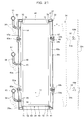
- a first water intake nozzle 53 is provided at the upper end of one of both sides of a filtration plate 49 of a membrane cartridge 34 orthogonal to a width direction A.
- a second water intake nozzle 85 is provided at the lower end of the other side thereof.
- a difference Hd between the heights of the first water intake nozzle 53 and the second water intake nozzle 85 is set to be equal to or larger than the length Lh in the sideward direction of the membrane cartridge 34 (i.e., Hd ⁇ Lh).
- a first water collecting pipe 55 for collecting treated water sucked from the first water intake nozzle 53 is provided above left or right one side of a frame body 37.
- a second water collecting pipe 87 for collecting treated water sucked from the second water intake nozzle 85 is provided below the left or right other side of the frame body 37.
- the first water collecting pipe 55 and the first water intake nozzle 53 are connected via a first connection pipe 56.
- the second water collecting pipe 87 and the second water intake nozzles 85 are connected via a second connection pipe 88.
- a first opened window 89 is formed at the upper end of left or right one side panel 39a and a second opened window 90 is formed at the lower end of the other side panel 39b.
- the first connection pipe 56 is inserted through the first opened window 89 and the second connection pipe 88 is inserted through the second opened window 90.
- the difference Hd between the heights of the first water intake nozzle 53 and the second water intake nozzle 85 is set to be equal to or larger than the length Lh in the sideward direction of the membrane cartridge 34. Consequently, it is possible to considerably reduce the overlap (interference) of the areas where the permeate can be obtained from the filtration membrane 50 by the respective water intake nozzles 53 and 85 and to sufficiently draw out the ability of the membrane cartridge 34.
- first and second water intake nozzles 53 and 85 are provided on both sides of the membrane cartridge 34, upflow 77 smoothly flows without hitting the first and second connection pipes 56 and 88. Consequently, matter adhering to the membrane surface of the membrane cartridge 34 is sufficiently removed. Vibration of the connection pipes 56 and 88 is reduced and it is possible to prevent a crack from occurring around the water intake nozzles 53 and 85.
- the membrane cartridge 34 can be pulled out from the inside of a casing 33 in the width direction A of the membrane cartridge 34 through the other side opening 45b and taken out to the outer side of the casing 33.
- the bolts 46 are screwed and, as indicated by the solid line of FIG. 19 , the other side panel 39b is attached to the frame body 37 and the other side opening 45b is closed. Consequently, the membrane cartridge 34 is housed in the inside of the casing 33 and a space S between the membrane cartridges 34 is accurately maintained at a predetermined space by space maintaining members 63a and 63b.
- the distal end of the first connection pipe 56 is fit in and connected to the first water intake nozzle 53 by using the first opened window 89 of the one side panel 39a and the distal end of the second connection pipe 88 is fit in and connected to the second water intake nozzle 85 by using the second opened window 90.
- the water intake nozzles 53 and 85 are provided on both sides of the membrane cartridge 34, the water intake nozzles 53 and 85 do not obstruct removal and insertion of the membrane cartridge 34.
- the submerged membrane separator of the type for inserting a membrane cartridge into and removing the membrane cartridge from a casing from the up-down direction as in the prior art when water intake nozzles are provided on both sides of the membrane cartridge, it is likely that the water intake nozzles obstruct removal and insertion of the membrane cartridge.
- the first, water intake nozzle 53 is provided at the upper end of one side of the membrane cartridge 34 and the second water intake nozzle 85 is provided at the lower end of the other side thereof.
- the first water intake nozzle 53 may be provided at the lower end of one side of the membrane cartridge 34 and the second water intake nozzle 85 may be provided at the upper end of the other side thereof.
- the upper and lower positions of the water collecting pipes 55 and 87, the connection pipes 56 and 88, and the opened windows 89 and 90 only have to be changed according to the upper and lower positions of the first and second water intake nozzles 53 and 85.
- the membrane cartridge 34 is removed from and inserted into the other side opening 45b.
- the membrane cartridges 34 may be removed from and inserted into one side opening 45a.
- the sixth embodiment is a modification of the fourth embodiment.
- first to third water intake nozzles 53, 85, and 92 (an example of water intake portions) are provided on one side of a filtration plate 49 of a membrane cartridge 34.
- the first water intake nozzle 53 is located at the upper end of one side of the membrane cartridge 34
- the third water intake nozzles 92 is located at the lower end of one side of the membrane cartridge 34
- the second water intake nozzle 85 is located between the upper first water intake nozzle 53 and the lower third water intake nozzle 92.
- a difference Hd1 between the heights of the first water intake nozzle 53 and the second water intake nozzle 85 is set to be equal to or larger than the length Lh in the sideward direction of the membrane cartridge 34 (i.e., Hd1-Lh).
- a difference Hd2 between the heights of the second water intake nozzle 85 and the third water intake nozzle 92 is set to be equal to or larger than the length Lh in the sideward direction of the membrane cartridge 34 (i.e., Hd2 ⁇ Lh).
- First to third water collecting pipes 55, 87, and 93 are provided on one of the left and right sides of a frame body 37.
- the first water collecting pipe 55 and the first water intake nozzle 53 are connected via a first connection pipe 56.
- the second water collecting pipe 87 and the second water intake nozzle 85 are connected via a second connection pipe 88.
- the third water collecting pipe 93 and the third water intake nozzle 92 are connected via a third connection pipe 94.
- First to third opened windows 89, 90, and 95 are formed in left or right one side panel 39a.
- the first opened window 89 is located at the upper end of the side panel 39a and opposed to the first water intake nozzle 53.
- the third opened window 95 is located at the lower end of the side panel 39a and opposed to the third water intake nozzle 92.
- the second opened window 90 is located between the upper first opened window 89 and the lower third opened window 95 and opposed to the second water intake nozzle 85.
- the first connection pipe 56 is inserted through the first opened window 89
- the second connection pipe 88 is inserted through the second opened window 90
- the third connection pipe 94 is inserted through the third opened window 95.
- first to third water intake nozzles 53, 85, and 92 are provided on one side of the membrane cartridge 34 and are located at different heights, a sufficient suction pressure acts on the entire membrane cartridge 34. Consequently, it is possible to obtain treated water (permeate) using the entire filtration membrane 50 effectively.
- the difference Hdl between the heights of the first water intake nozzle 53 and the second water intake nozzle 85 is set to be equal to or larger than the length Lh in the sideward direction of the membrane cartridge 34 and the difference Hd2 between the heights of the second water intake nozzle 85 and the third water intake nozzle 92 is set to be equal to or larger than the length Lh in the sideward direction of the membrane cartridge 34. Consequently, it is possible to considerably reduce the overlap (interference) of the areas where the permeate can be obtained from the filtration membrane 50 by the respective water intake nozzles 53, 85, and 92 and to sufficiently draw out the ability of the membrane cartridge 34.
- connection pipes 56, 88, and 94 Since upflow 77 smoothly flows without hitting the first to third connection pipes 56, 88, and 94, the matter adhering to the membrane surface of the membrane cartridge 34 is sufficiently removed. Vibration of the connection pipes 56, 88, and 94 is reduced and it is possible to prevent a crack from occurring around the water intake nozzles 53, 85, and 92.
- the other side panel 39b is removed to open the other side opening 45b and remove the left or right other space maintaining member 63b from the frame body 37.
- the membrane cartridge 34 is pulled out from the inside of a casing 33 in the width direction A of the membrane cartridge 34 through the other side opening 45b and taken out to the outer side of the casing 33.
- the distal end of the first connection pipe 56 is fit in and connected to the first water intake nozzle 53 by using the first opened window 89 of the one side panel 39a.
- the distal end of the second connection pipe 88 is fit in and connected to the second water intake nozzle 85 by using the second opened window 90.
- the distal end of the third connection pipe 94 is fit in and connected to the third water intake nozzle 92 by using the third opened window 95.
- the plurality of water intake nozzles 53, 85, and 92 are provided on one side of the membrane cartridge 34.
- the water intake nozzles 53, 85, and 92 may be provided on the opposite other side thereof.
- the water collecting pipes 55, 87, and 93, the connection pipes 56, 88, and 94, and the opened windows 89, 90, and 95 are also located on the opposite other side thereof.
- the one side panel 39a is removed and the membrane cartridge 34 is removed from and inserted into one side opening 45a.
- the three water intake nozzles 53, 85, and 92 are provided on the side of the membrane cartridge 34.
- two or four or more water intake nozzles 53, 85, and 92 may be provided according to the size of the membrane cartridge 34.
- the number of each of the water collecting pipes 55, 87 and 93, the connection pipes 56, 88 and 94, and the opened windows 89, 90 and 95 only has to be caused to correspond to the number of the water intake nozzles 53, 85 and 92.
- first to third water intake nozzles 53, 85, and 92 are provided on sides of a filtration plate 49 of a membrane cartridge 34.
- the first water intake nozzle 53 is located at the upper end of one side of the membrane cartridge 34.
- the third water intake nozzle 92 is located at the lower end of one side of the membrane cartridge 34.
- the second water intake nozzle 85 is provided on the other side of the membrane cartridge 34 and is located between the upper first water intake nozzle 53 and the lower third water intake nozzle 92.
- a difference Hdl, between the heights of the first water intake nozzle 53 and the second water intake nozzle 85 is set to be equal to or larger than the length Lh in the sideward direction of the membrane cartridge 34 (i.e., Hd1 ⁇ Lh).
- a difference Hd2 between the heights of the second water intake nozzle 85 and the third water intake nozzle 92 is set to be equal to or larger than the length Lh in the sideward direction of the membrane cartridge 34 (i.e., Hd2>Lh).
- First and third water collecting pipes 55 and 93 are provided on left or right one side of a frame body 37.
- a second water collecting pipe 87 is provided on the left or right other side of the frame body 37.
- the first water collecting pipe 55 and the first water intake nozzle 53 are connected via a first connection pipe 56.
- the second water collecting pipe 87 and the second water intake nozzle 85 are connected via a second connection pipe 88.
- the third water collecting pipe 93 and the third water intake nozzle 92 are connected via a third connection pipe 94.
- First and third opened windows 89 and 95 are formed in left or right one side panel 39a.
- a second opened window 90 is formed in the left or right other side panel 39b.
- the first opened window 89 is located at the upper end of the one side panel 39a and opposed to the first water intake nozzle 53.
- the third opened window 95 is located at the lower end of the one side panel 39a and opposed to the third water intake nozzle 92.
- the second opened window 90 is located between the upper and lower ends of the other side panel 39b and opposed to the second water intake nozzle 85.
- the difference Hd1 between the heights of the first water intake nozzle 53 and the second water intake nozzle 85 is set to be equal to or larger than the length Lh in the sideward direction of the membrane cartridge 34 and the difference Hd2 between the heights of the second water intake nozzle 85 and the third water intake nozzle 92 is set to be equal to or larger than the length Lh in the sideward direction thereof. Consequently, it is possible to considerably reduce the overlap (interference) of the areas where the permeate can be obtained from the filtration membrane 50 by the respective water intake nozzles 53, 85, and 92 and sufficiently draw out the ability of the membrane cartridge 34.
- connection pipes 56, 88, and 94 Since upflow 77 smoothly flows without hitting the first to third connection pipes 56, 88, and 94, the matter adhering to the membrane surface of the membrane cartridge 34 is sufficiently removed. Vibration of the connection pipes 56, 88, and 94 is reduced and it is possible to prevent a crack from occurring around the water intake nozzles 53, 85, and 92.
- the other side panel 39b is removed to open the other side opening 45b and remove the left or right other space maintaining member 63b from the frame body 37.
- the membrane cartridge 34 is pulled out from the inside of a casing 33 in the width direction A of the membrane cartridge 34 through the other side opening 45b and taken out to the outer side of the casing 33.
- the distal end of the first connection pipe 56 is fit in and connected to the first water intake nozzle 53 by using the first opened window 89 of the one side panel 39a.
- the distal end of the third connection pipe 94 is fit in and connected to the third water intake nozzle 92 by using the third opened window 95.
- the distil end of the second connection pipe 88 is fit in and connected to the second water intake nozzle 85 by using the second opened window 90 of the other side panel 39b.
- the water intake nozzles 53 and 92 are provided on one side of the membrane cartridge 34 and the water intake nozzle 85 is provided on the other side of the membrane cartridge 34.
- the water intake nozzles 53 and 92 may be provided on the other side thereof and the water intake nozzle 85 may be provided on one side thereof.
- the positions of the water collecting pipes 55, 87, and 93, the connection pipes 56, 88, and 94, and the opened windows 89, 90, and 95 only have to be respectively changed to the opposite sides according to the positions of the water intake nozzles 53, 85, and 92.
- One or three or more water intake nozzles 53 and 92 may be provided on one side of the membrane cartridge 34 or two or more water intake nozzles 85 may be provided on the other side of the membrane cartridge 34.
- first to fourth water intake nozzles 53, 85, 92, and 96 are provided on the sides of a filtration plate 49 of a membrane cartridge 34.
- the first water intake nozzle 53 is located at the upper end of one side of the membrane cartridge 34.
- the second water intake nozzle 85 is located between the upper and lower ends of one side of the membrane cartridge 34.
- the third water intake nozzle 92 is located at the upper end of the other side of the membrane cartridge 34.
- the fourth water intake nozzle 96 is located between the upper and lower ends of the other side of the membrane cartridge 34.
- the height from the lower side of the membrane cartridge 34 to the second water intake nozzle 85 is smaller than the height from the tower side of the membrane cartridge 34 to the first water intake nozzle 53.
- the height from the lower side of the membrane cartridge 34 to the fourth water intake nozzle 96 is smaller than the height from the lower side of the membrane cartridge 34 to the third water intake nozzle 92.
- the heights from the lower side of the membrane cartridge 34 to the first and third water intake nozzles 53 and 92 are the same.
- the heights from the lower side of the membrane cartridge 34 to the second and fourth water intake nozzles 85 and 96 are the same.
- a difference Hdl between the heights of the first water intake nozzle 53 and the second water intake nozzle 85 is set to be equal to or larger than the length Lh in the sideward direction of the membrane cartridge 34 (i.e., Hd1 ⁇ Lh).
- a difference Hd2 between the heights of the third water intake nozzle 92 and the fourth water intake nozzle 96 is set to be equal to or larger than the length Lh in the sideward direction of the membrane cartridge 34 (i.e., Hd2 ⁇ Lh).
- a first water collecting pipe 55 for collecting treated water sucked from the first and second water intake nozzles 53 and 85 of the membrane cartridges 34 is provided in the front-rear direction above left or right one side of a frame body 37.
- a second water collecting pipe 87 for collecting treated water sucked from the third and fourth water intake nozzles 92 and 96 of the membrane cartridges 34 is provided above the left or right other side of the frame body 37.
- the first water collecting pipe 55 and the first water intake nozzle 53 are connected via a first connection pipe 56.
- the first water collecting pipe 55 and the second water intake nozzle 85 are connected via a second connection pipe 88.
- the second water collecting pipe 87 and the third water intake nozzles 92 are connected via a third connection pipe 94.
- the second water collecting pipe 87 and the fourth water intake nozzle 96 are connected via a fourth connection pipe 97.
- the first to fourth connection pipes 56, 88, 94, and 97 have flexibility.
- First and second opened windows 89 and 90 are formed in left or right one side panel 39a.
- the first opened window 89 is located at the upper end of the side panel 39a and opposed to the first water intake nozzle 53.
- the second opened window 90 is located between the upper and lower ends of the side panel 39a and opposed to the second water intake nozzle 85.
- the first connection pipe 56 is inserted through the first opened window 89 and the second connection pipe 88 is inserted through the second opened window 90.
- Third and fourth opened windows 95 and 98 are formed in the left or right other side panel 39b.
- the third opened window 95 is located at the upper end of the side panel 39b and opposed to the third water intake nozzle 92.
- the fourth opened window 98 is located between the upper and lower ends of the side panel 39b and opposed to the fourth water intake nozzle 96.
- the third connection pipe 94 is inserted through the third opened window 95 and the fourth connection pipe 97 is inserted through the fourth opened window 98.
- the first and second water intake nozzles 53 and 85 are provided on one side of the membrane cartridge 34 and located at different heights.
- the third and fourth water intake nozzles 92 and 96 are provided on the other side of the membrane cartridge 34 and located at different heights. Therefore, a sufficient suction pressure acts on the entire membrane cartridge 34. Consequently, it is possible to obtain treated water (permeate) using the entire filtration membrane 50 effectively.
- connection pipes 56, 88, 94, and 97 Since upflow 77 smoothly flows without hitting the first to fourth connection pipes 56, 88, 94, and 97, the matter adhering to the membrane surface of the membrane cartridge 34 is sufficiently removed. Vibration of the connection pipes 56, 88, 94, and 97 is reduced and it is possible to prevent a crack from occurring around the water intake nozzles 53, 85, 92, and 96.
- the first and second connection pipes 56 and 88 are connected to the common first water collecting pipe 55 and the third and fourth connection pipes 94 and 97 are connected to the common second water collecting pipe 87. Therefore, it is possible to reduce the number of the water collecting pipes 55 and 87 with respect to the number of the water intake nozzles 53, 85, 92, and 96.
- the other side panel 39b is removed to open the other side opening 45b and remove the left or right other space maintaining member 63b from the frame body 37.
- the membrane cartridge 34 is pulled out from the inside of a casing 33 in the width direction A of the membrane cartridge 34 through the other side opening 45b and taken out to the outer side of the casing 33.
- the distal end of the first connection pipe 56 is fit in and connected to the first water intake nozzle 53 by using the first opened window 89.
- the distal end of the second connection pipe 88 is fit in and connected to the second water intake nozzle 85 by using the second opened window 90.
- the distal end of the third connection pipe 94 is fit in and connected to the third water intake nozzle 92 by using the third opened window 95.
- the distal end of the fourth connection pipe 97 is fit in and connected to the fourth water intake nozzle 96 by using the fourth opened window 98.
- the two water intake nozzles 53 and 85 are provided on one side of the membrane cartridge 34. However, one or three or more water intake nozzles 53 and 85 may be provided.
- the two water intake nozzles 92 and 96 are provided on the other side of the membrane cartridge 34. However, one or three or more water intake nozzles 92 and 96 may be provided. In this case, the numbers and positions of the connection pipes 56, 88, 94, and 97 and the opened windows 89, 90, 95, and 98 only have to be changed according to the number and positions of the water intake nozzles 53, 85, 92, and 96.
- the opened windows 89 and 90 are formed in the one side panel 39a.
- the opened windows 95 and 98 are formed in the other side panel 39b.
- the membrane cartridge 34 is formed in an elongated rectangle.
- the membrane cartridge 34 is not limited to the rectangle.
- the membrane cartridge 34 may be formed in a shape with a side 34a inclining with respect to the vertical direction, for example, as shown in FIG. 26 as a ninth embodiment, as long as the shape is an elongated shape.
- the membrane cartridge 34 may be formed in a shape with four corners 34b formed in a circular shape as shown in FIG. 27 as a tenth embodiment.
- the upper limit of the aspect ratio is desirably equal to or smaller than 4.
Landscapes
- Chemical & Material Sciences (AREA)
- Chemical Kinetics & Catalysis (AREA)
- Engineering & Computer Science (AREA)
- Water Supply & Treatment (AREA)
- Separation Using Semi-Permeable Membranes (AREA)
Applications Claiming Priority (3)
| Application Number | Priority Date | Filing Date | Title |
|---|---|---|---|
| JP2007307504 | 2007-11-28 | ||
| JP2008154930A JP5376424B2 (ja) | 2007-11-28 | 2008-06-13 | 浸漬型膜分離装置 |
| PCT/JP2008/003484 WO2009069294A1 (fr) | 2007-11-28 | 2008-11-27 | Appareil de séparation sur film de type à immersion et cartouche de film |
Publications (3)
| Publication Number | Publication Date |
|---|---|
| EP2228124A1 true EP2228124A1 (fr) | 2010-09-15 |
| EP2228124A4 EP2228124A4 (fr) | 2012-08-22 |
| EP2228124B1 EP2228124B1 (fr) | 2021-02-17 |
Family
ID=40678205
Family Applications (1)
| Application Number | Title | Priority Date | Filing Date |
|---|---|---|---|
| EP08853823.6A Active EP2228124B1 (fr) | 2007-11-28 | 2008-11-27 | Appareil de séparation sur film de type à immersion |
Country Status (5)
| Country | Link |
|---|---|
| US (1) | US9878290B2 (fr) |
| EP (1) | EP2228124B1 (fr) |
| JP (1) | JP5376424B2 (fr) |
| CN (1) | CN101878062B (fr) |
| WO (1) | WO2009069294A1 (fr) |
Cited By (3)
| Publication number | Priority date | Publication date | Assignee | Title |
|---|---|---|---|---|
| EP2873650A4 (fr) * | 2012-07-10 | 2016-06-29 | Toray Industries | Élément unitaire, module de membranes de séparation et procédé pour connecter/déconnecter un élément de membranes de séparation |
| WO2017067818A1 (fr) * | 2015-10-21 | 2017-04-27 | Itn Nanovation Ag | Procédé de nettoyage d'une membrane poreuse |
| EP3498362A4 (fr) * | 2016-08-11 | 2020-04-22 | Amogreentech Co., Ltd. | Module filtre de type à plaque pour traitement d'eau, et ensemble filtre pour traitement d'eau le comprenant |
Families Citing this family (10)
| Publication number | Priority date | Publication date | Assignee | Title |
|---|---|---|---|---|
| USD648007S1 (en) * | 2010-08-02 | 2011-11-01 | Asahi Kasei Chemicals Corporation | Air diffusion pipe for a filter |
| USD648009S1 (en) * | 2010-08-05 | 2011-11-01 | Asahi Kasei Chemicals Corporation | Pipe for a filter |
| KR101044350B1 (ko) * | 2011-01-12 | 2011-06-29 | 박병선 | 수처리 장치 |
| DE102013207250A1 (de) * | 2013-04-22 | 2014-10-23 | Mahle International Gmbh | Luftfiltereinrichtung |
| JP6156480B2 (ja) * | 2015-12-25 | 2017-07-05 | 株式会社明電舎 | 膜カセット及び膜ユニット |
| SG11201810460UA (en) | 2016-05-31 | 2018-12-28 | Meidensha Electric Mfg Co Ltd | Film separation device, structure for arranging film element, and film cassette and film unit |
| IL289660A (en) * | 2019-07-16 | 2022-07-01 | Fibracast Ltd | System and method for feeding submerged membrane units |
| JP6897832B1 (ja) * | 2020-03-23 | 2021-07-07 | 株式会社明電舎 | 支持構造および膜濾過装置 |
| KR20210132921A (ko) * | 2020-04-28 | 2021-11-05 | 주식회사 아모그린텍 | 중력식 정수장치용 필터모듈 및 이를 포함하는 중력식 정수장치 |
| CN116651214A (zh) * | 2023-07-07 | 2023-08-29 | 维尔利环保科技集团股份有限公司 | 一种用于高浓度有机废水净化的新型高效平板膜反应器 |
Family Cites Families (13)
| Publication number | Priority date | Publication date | Assignee | Title |
|---|---|---|---|---|
| US2312015A (en) * | 1940-09-09 | 1943-02-23 | Brosites Machine Company Inc | Frame for dialyzing apparatus |
| JPH07299339A (ja) * | 1994-05-09 | 1995-11-14 | Kubota Corp | 平板型膜分離装置 |
| JP3575072B2 (ja) * | 1994-08-01 | 2004-10-06 | 栗田工業株式会社 | 浸漬型膜分離装置 |
| US7037426B2 (en) * | 2000-05-04 | 2006-05-02 | Zenon Environmental Inc. | Immersed membrane apparatus |
| JPH10180052A (ja) | 1996-12-27 | 1998-07-07 | Inax Corp | 膜分離装置 |
| JPH11244672A (ja) * | 1998-03-02 | 1999-09-14 | Daisen Membrane Systems Kk | 平膜エレメント及びこれを用いた平膜モジュール |
| JP3606735B2 (ja) * | 1998-04-21 | 2005-01-05 | 株式会社クボタ | 活性汚泥用膜カートリッジの再生方法及びその装置 |
| CA2290053C (fr) * | 1999-11-18 | 2009-10-20 | Zenon Environmental Inc. | Module de membranes immergees et procede |
| US20040007527A1 (en) | 1998-11-23 | 2004-01-15 | Zenon Environmental Inc. | Membrane filtration device and process |
| JP2002362051A (ja) | 2001-06-05 | 2002-12-18 | Fuji Photo Film Co Ltd | 平版印刷版用原版 |
| JP2002361051A (ja) * | 2001-06-07 | 2002-12-17 | Kubota Corp | 膜カートリッジ |
| US7279215B2 (en) * | 2003-12-03 | 2007-10-09 | 3M Innovative Properties Company | Membrane modules and integrated membrane cassettes |
| KR20080110862A (ko) * | 2006-03-27 | 2008-12-19 | 도레이 카부시키가이샤 | 막 엘리먼트, 막 유닛 및 다단 적층 막 유닛 |
-
2008
- 2008-06-13 JP JP2008154930A patent/JP5376424B2/ja active Active
- 2008-11-27 EP EP08853823.6A patent/EP2228124B1/fr active Active
- 2008-11-27 US US12/734,883 patent/US9878290B2/en active Active
- 2008-11-27 CN CN200880118165.1A patent/CN101878062B/zh active Active
- 2008-11-27 WO PCT/JP2008/003484 patent/WO2009069294A1/fr not_active Ceased
Cited By (4)
| Publication number | Priority date | Publication date | Assignee | Title |
|---|---|---|---|---|
| EP2873650A4 (fr) * | 2012-07-10 | 2016-06-29 | Toray Industries | Élément unitaire, module de membranes de séparation et procédé pour connecter/déconnecter un élément de membranes de séparation |
| WO2017067818A1 (fr) * | 2015-10-21 | 2017-04-27 | Itn Nanovation Ag | Procédé de nettoyage d'une membrane poreuse |
| EP3498362A4 (fr) * | 2016-08-11 | 2020-04-22 | Amogreentech Co., Ltd. | Module filtre de type à plaque pour traitement d'eau, et ensemble filtre pour traitement d'eau le comprenant |
| US10933379B2 (en) | 2016-08-11 | 2021-03-02 | Amogreentech Co., Ltd. | Plate-type filter module for water treatment and filter assembly for water treatment comprising same |
Also Published As
| Publication number | Publication date |
|---|---|
| US9878290B2 (en) | 2018-01-30 |
| EP2228124B1 (fr) | 2021-02-17 |
| US20110005987A1 (en) | 2011-01-13 |
| JP5376424B2 (ja) | 2013-12-25 |
| WO2009069294A1 (fr) | 2009-06-04 |
| JP2009148743A (ja) | 2009-07-09 |
| CN101878062A (zh) | 2010-11-03 |
| CN101878062B (zh) | 2014-11-12 |
| EP2228124A4 (fr) | 2012-08-22 |
Similar Documents
| Publication | Publication Date | Title |
|---|---|---|
| EP2228124A1 (fr) | Appareil de séparation sur film de type à immersion et cartouche de film | |
| US8821726B2 (en) | Submerged membrane separator | |
| EP1945333B1 (fr) | Ensemble pour filtration d'eau pour réduire le volume de lavage à contre-courant | |
| US8647507B2 (en) | Membrane cartridge | |
| CA2579857A1 (fr) | Module de filtration par membranes et processus de nettoyage | |
| CA2501628A1 (fr) | Agencement de filtration et de lavage a contre-courant pour modules de membranes | |
| JP2018108585A (ja) | 散気装置、散気方法、及び水処理装置 | |
| CN101541405A (zh) | 中空纤维膜的盒模块 | |
| JP2010264355A (ja) | 浮上油回収装置 | |
| KR200368690Y1 (ko) | 침지형 평막 여과장치 | |
| WO2007108145A1 (fr) | Dispositif de filtrage pour réservoir d'eau | |
| JP5377028B2 (ja) | 膜分離装置 | |
| JP2010119976A (ja) | 散気装置 | |
| JP2010234228A (ja) | 膜分離装置の洗浄装置および洗浄方法 | |
| JP4996379B2 (ja) | ろ過装置 | |
| CN210855526U (zh) | 一种含油污水的气浮除油装置 | |
| JP5275082B2 (ja) | 散気装置及び浸漬膜ユニット | |
| JP2006007179A (ja) | 膜ろ過装置および膜ろ過方法 | |
| JPH07275668A (ja) | 膜分離ユニット | |
| KR20060015887A (ko) | 침지형 평막 여과장치 | |
| JP2005262045A (ja) | 移動床式砂ろ過装置およびそのエアリフト管の抜き差し方法 | |
| JP2015231592A (ja) | 散気装置の運転方法 | |
| AU2006284524A1 (en) | An assembly for water filtration using a tube manifold to minimise backwash | |
| JP2002153870A (ja) | 膜処理型排水処理施設用メンテナンス車 |
Legal Events
| Date | Code | Title | Description |
|---|---|---|---|
| PUAI | Public reference made under article 153(3) epc to a published international application that has entered the european phase |
Free format text: ORIGINAL CODE: 0009012 |
|
| 17P | Request for examination filed |
Effective date: 20100628 |
|
| AK | Designated contracting states |
Kind code of ref document: A1 Designated state(s): AT BE BG CH CY CZ DE DK EE ES FI FR GB GR HR HU IE IS IT LI LT LU LV MC MT NL NO PL PT RO SE SI SK TR |
|
| AX | Request for extension of the european patent |
Extension state: AL BA MK RS |
|
| DAX | Request for extension of the european patent (deleted) | ||
| A4 | Supplementary search report drawn up and despatched |
Effective date: 20120723 |
|
| RIC1 | Information provided on ipc code assigned before grant |
Ipc: B01D 65/02 20060101ALI20120717BHEP Ipc: B01D 63/08 20060101AFI20120717BHEP Ipc: B01D 61/18 20060101ALI20120717BHEP |
|
| STAA | Information on the status of an ep patent application or granted ep patent |
Free format text: STATUS: EXAMINATION IS IN PROGRESS |
|
| 17Q | First examination report despatched |
Effective date: 20171205 |
|
| GRAP | Despatch of communication of intention to grant a patent |
Free format text: ORIGINAL CODE: EPIDOSNIGR1 |
|
| STAA | Information on the status of an ep patent application or granted ep patent |
Free format text: STATUS: GRANT OF PATENT IS INTENDED |
|
| INTG | Intention to grant announced |
Effective date: 20201029 |
|
| RIN1 | Information on inventor provided before grant (corrected) |
Inventor name: ISHIKAWA, KIMIHIRO Inventor name: UEJIMA, TATSUYA Inventor name: SASAKI, TOMOHIKO Inventor name: MATSUZAKI, YOSHIO |
|
| GRAS | Grant fee paid |
Free format text: ORIGINAL CODE: EPIDOSNIGR3 |
|
| GRAA | (expected) grant |
Free format text: ORIGINAL CODE: 0009210 |
|
| STAA | Information on the status of an ep patent application or granted ep patent |
Free format text: STATUS: THE PATENT HAS BEEN GRANTED |
|
| AK | Designated contracting states |
Kind code of ref document: B1 Designated state(s): AT BE BG CH CY CZ DE DK EE ES FI FR GB GR HR HU IE IS IT LI LT LU LV MC MT NL NO PL PT RO SE SI SK TR |
|
| REG | Reference to a national code |
Ref country code: GB Ref legal event code: FG4D |
|
| REG | Reference to a national code |
Ref country code: CH Ref legal event code: EP |
|
| REG | Reference to a national code |
Ref country code: DE Ref legal event code: R096 Ref document number: 602008063712 Country of ref document: DE |
|
| REG | Reference to a national code |
Ref country code: AT Ref legal event code: REF Ref document number: 1360734 Country of ref document: AT Kind code of ref document: T Effective date: 20210315 |
|
| REG | Reference to a national code |
Ref country code: IE Ref legal event code: FG4D |
|
| REG | Reference to a national code |
Ref country code: LT Ref legal event code: MG9D |
|
| REG | Reference to a national code |
Ref country code: NL Ref legal event code: MP Effective date: 20210217 |
|
| PG25 | Lapsed in a contracting state [announced via postgrant information from national office to epo] |
Ref country code: NO Free format text: LAPSE BECAUSE OF FAILURE TO SUBMIT A TRANSLATION OF THE DESCRIPTION OR TO PAY THE FEE WITHIN THE PRESCRIBED TIME-LIMIT Effective date: 20210517 Ref country code: BG Free format text: LAPSE BECAUSE OF FAILURE TO SUBMIT A TRANSLATION OF THE DESCRIPTION OR TO PAY THE FEE WITHIN THE PRESCRIBED TIME-LIMIT Effective date: 20210517 Ref country code: PT Free format text: LAPSE BECAUSE OF FAILURE TO SUBMIT A TRANSLATION OF THE DESCRIPTION OR TO PAY THE FEE WITHIN THE PRESCRIBED TIME-LIMIT Effective date: 20210617 Ref country code: GR Free format text: LAPSE BECAUSE OF FAILURE TO SUBMIT A TRANSLATION OF THE DESCRIPTION OR TO PAY THE FEE WITHIN THE PRESCRIBED TIME-LIMIT Effective date: 20210518 Ref country code: HR Free format text: LAPSE BECAUSE OF FAILURE TO SUBMIT A TRANSLATION OF THE DESCRIPTION OR TO PAY THE FEE WITHIN THE PRESCRIBED TIME-LIMIT Effective date: 20210217 Ref country code: FI Free format text: LAPSE BECAUSE OF FAILURE TO SUBMIT A TRANSLATION OF THE DESCRIPTION OR TO PAY THE FEE WITHIN THE PRESCRIBED TIME-LIMIT Effective date: 20210217 Ref country code: LT Free format text: LAPSE BECAUSE OF FAILURE TO SUBMIT A TRANSLATION OF THE DESCRIPTION OR TO PAY THE FEE WITHIN THE PRESCRIBED TIME-LIMIT Effective date: 20210217 |
|
| REG | Reference to a national code |
Ref country code: AT Ref legal event code: MK05 Ref document number: 1360734 Country of ref document: AT Kind code of ref document: T Effective date: 20210217 |
|
| PG25 | Lapsed in a contracting state [announced via postgrant information from national office to epo] |
Ref country code: SE Free format text: LAPSE BECAUSE OF FAILURE TO SUBMIT A TRANSLATION OF THE DESCRIPTION OR TO PAY THE FEE WITHIN THE PRESCRIBED TIME-LIMIT Effective date: 20210217 Ref country code: PL Free format text: LAPSE BECAUSE OF FAILURE TO SUBMIT A TRANSLATION OF THE DESCRIPTION OR TO PAY THE FEE WITHIN THE PRESCRIBED TIME-LIMIT Effective date: 20210217 Ref country code: LV Free format text: LAPSE BECAUSE OF FAILURE TO SUBMIT A TRANSLATION OF THE DESCRIPTION OR TO PAY THE FEE WITHIN THE PRESCRIBED TIME-LIMIT Effective date: 20210217 Ref country code: NL Free format text: LAPSE BECAUSE OF FAILURE TO SUBMIT A TRANSLATION OF THE DESCRIPTION OR TO PAY THE FEE WITHIN THE PRESCRIBED TIME-LIMIT Effective date: 20210217 |
|
| PG25 | Lapsed in a contracting state [announced via postgrant information from national office to epo] |
Ref country code: IS Free format text: LAPSE BECAUSE OF FAILURE TO SUBMIT A TRANSLATION OF THE DESCRIPTION OR TO PAY THE FEE WITHIN THE PRESCRIBED TIME-LIMIT Effective date: 20210617 |
|
| PG25 | Lapsed in a contracting state [announced via postgrant information from national office to epo] |
Ref country code: AT Free format text: LAPSE BECAUSE OF FAILURE TO SUBMIT A TRANSLATION OF THE DESCRIPTION OR TO PAY THE FEE WITHIN THE PRESCRIBED TIME-LIMIT Effective date: 20210217 Ref country code: EE Free format text: LAPSE BECAUSE OF FAILURE TO SUBMIT A TRANSLATION OF THE DESCRIPTION OR TO PAY THE FEE WITHIN THE PRESCRIBED TIME-LIMIT Effective date: 20210217 Ref country code: CZ Free format text: LAPSE BECAUSE OF FAILURE TO SUBMIT A TRANSLATION OF THE DESCRIPTION OR TO PAY THE FEE WITHIN THE PRESCRIBED TIME-LIMIT Effective date: 20210217 |
|
| REG | Reference to a national code |
Ref country code: DE Ref legal event code: R097 Ref document number: 602008063712 Country of ref document: DE |
|
| PG25 | Lapsed in a contracting state [announced via postgrant information from national office to epo] |
Ref country code: RO Free format text: LAPSE BECAUSE OF FAILURE TO SUBMIT A TRANSLATION OF THE DESCRIPTION OR TO PAY THE FEE WITHIN THE PRESCRIBED TIME-LIMIT Effective date: 20210217 Ref country code: SK Free format text: LAPSE BECAUSE OF FAILURE TO SUBMIT A TRANSLATION OF THE DESCRIPTION OR TO PAY THE FEE WITHIN THE PRESCRIBED TIME-LIMIT Effective date: 20210217 Ref country code: DK Free format text: LAPSE BECAUSE OF FAILURE TO SUBMIT A TRANSLATION OF THE DESCRIPTION OR TO PAY THE FEE WITHIN THE PRESCRIBED TIME-LIMIT Effective date: 20210217 Ref country code: ES Free format text: LAPSE BECAUSE OF FAILURE TO SUBMIT A TRANSLATION OF THE DESCRIPTION OR TO PAY THE FEE WITHIN THE PRESCRIBED TIME-LIMIT Effective date: 20210217 |
|
| PLBE | No opposition filed within time limit |
Free format text: ORIGINAL CODE: 0009261 |
|
| STAA | Information on the status of an ep patent application or granted ep patent |
Free format text: STATUS: NO OPPOSITION FILED WITHIN TIME LIMIT |
|
| 26N | No opposition filed |
Effective date: 20211118 |
|
| PG25 | Lapsed in a contracting state [announced via postgrant information from national office to epo] |
Ref country code: SI Free format text: LAPSE BECAUSE OF FAILURE TO SUBMIT A TRANSLATION OF THE DESCRIPTION OR TO PAY THE FEE WITHIN THE PRESCRIBED TIME-LIMIT Effective date: 20210217 |
|
| PG25 | Lapsed in a contracting state [announced via postgrant information from national office to epo] |
Ref country code: IS Free format text: LAPSE BECAUSE OF FAILURE TO SUBMIT A TRANSLATION OF THE DESCRIPTION OR TO PAY THE FEE WITHIN THE PRESCRIBED TIME-LIMIT Effective date: 20210617 |
|
| REG | Reference to a national code |
Ref country code: DE Ref legal event code: R119 Ref document number: 602008063712 Country of ref document: DE |
|
| PG25 | Lapsed in a contracting state [announced via postgrant information from national office to epo] |
Ref country code: MC Free format text: LAPSE BECAUSE OF FAILURE TO SUBMIT A TRANSLATION OF THE DESCRIPTION OR TO PAY THE FEE WITHIN THE PRESCRIBED TIME-LIMIT Effective date: 20210217 |
|
| REG | Reference to a national code |
Ref country code: CH Ref legal event code: PL |
|
| GBPC | Gb: european patent ceased through non-payment of renewal fee |
Effective date: 20211127 |
|
| PG25 | Lapsed in a contracting state [announced via postgrant information from national office to epo] |
Ref country code: LU Free format text: LAPSE BECAUSE OF NON-PAYMENT OF DUE FEES Effective date: 20211127 Ref country code: BE Free format text: LAPSE BECAUSE OF NON-PAYMENT OF DUE FEES Effective date: 20211130 |
|
| REG | Reference to a national code |
Ref country code: BE Ref legal event code: MM Effective date: 20211130 |
|
| PG25 | Lapsed in a contracting state [announced via postgrant information from national office to epo] |
Ref country code: LI Free format text: LAPSE BECAUSE OF NON-PAYMENT OF DUE FEES Effective date: 20211130 Ref country code: CH Free format text: LAPSE BECAUSE OF NON-PAYMENT OF DUE FEES Effective date: 20211130 |
|
| PG25 | Lapsed in a contracting state [announced via postgrant information from national office to epo] |
Ref country code: IE Free format text: LAPSE BECAUSE OF NON-PAYMENT OF DUE FEES Effective date: 20211127 Ref country code: GB Free format text: LAPSE BECAUSE OF NON-PAYMENT OF DUE FEES Effective date: 20211127 Ref country code: DE Free format text: LAPSE BECAUSE OF NON-PAYMENT OF DUE FEES Effective date: 20220601 |
|
| PG25 | Lapsed in a contracting state [announced via postgrant information from national office to epo] |
Ref country code: HU Free format text: LAPSE BECAUSE OF FAILURE TO SUBMIT A TRANSLATION OF THE DESCRIPTION OR TO PAY THE FEE WITHIN THE PRESCRIBED TIME-LIMIT; INVALID AB INITIO Effective date: 20081127 Ref country code: CY Free format text: LAPSE BECAUSE OF FAILURE TO SUBMIT A TRANSLATION OF THE DESCRIPTION OR TO PAY THE FEE WITHIN THE PRESCRIBED TIME-LIMIT Effective date: 20210217 |
|
| PG25 | Lapsed in a contracting state [announced via postgrant information from national office to epo] |
Ref country code: MT Free format text: LAPSE BECAUSE OF FAILURE TO SUBMIT A TRANSLATION OF THE DESCRIPTION OR TO PAY THE FEE WITHIN THE PRESCRIBED TIME-LIMIT Effective date: 20210217 |
|
| PGFP | Annual fee paid to national office [announced via postgrant information from national office to epo] |
Ref country code: FR Payment date: 20250930 Year of fee payment: 18 |
|
| PG25 | Lapsed in a contracting state [announced via postgrant information from national office to epo] |
Ref country code: TR Free format text: LAPSE BECAUSE OF FAILURE TO SUBMIT A TRANSLATION OF THE DESCRIPTION OR TO PAY THE FEE WITHIN THE PRESCRIBED TIME-LIMIT Effective date: 20210217 |
|
| PGFP | Annual fee paid to national office [announced via postgrant information from national office to epo] |
Ref country code: IT Payment date: 20251022 Year of fee payment: 18 |