EP2228162B1 - Suspendable resistance spot welding gun - Google Patents
Suspendable resistance spot welding gun Download PDFInfo
- Publication number
- EP2228162B1 EP2228162B1 EP10002343.1A EP10002343A EP2228162B1 EP 2228162 B1 EP2228162 B1 EP 2228162B1 EP 10002343 A EP10002343 A EP 10002343A EP 2228162 B1 EP2228162 B1 EP 2228162B1
- Authority
- EP
- European Patent Office
- Prior art keywords
- welding gun
- support member
- gun according
- electrode holder
- plate
- Prior art date
- Legal status (The legal status is an assumption and is not a legal conclusion. Google has not performed a legal analysis and makes no representation as to the accuracy of the status listed.)
- Active
Links
Images


Classifications
-
- B—PERFORMING OPERATIONS; TRANSPORTING
- B23—MACHINE TOOLS; METAL-WORKING NOT OTHERWISE PROVIDED FOR
- B23K—SOLDERING OR UNSOLDERING; WELDING; CLADDING OR PLATING BY SOLDERING OR WELDING; CUTTING BY APPLYING HEAT LOCALLY, e.g. FLAME CUTTING; WORKING BY LASER BEAM
- B23K11/00—Resistance welding; Severing by resistance heating
- B23K11/28—Portable welding equipment
Definitions
- the present invention refers to resistance spot welding guns, which can be used, for example, for carrying out welding operations on motor vehicle body members, during which the guns need to be kept suspended in order to be moved in the space, either manually by an operator or by a robotized driving device such as the arm of an anthropomorphic robot, or need to be suspended on a stationary support base in which case a workpiece to be welded is moved by a handling apparatus.
- a robotized driving device such as the arm of an anthropomorphic robot
- the invention relates to a gun of the type defined in the preamble of appended claim 1.
- a welding gun of the type mentioned above is known for example from EP-A-1 782 909 .
- the structure of the gun of this document comprises a circular plate support member by which the gun is articulably suspended so that it can be directed in the space according to different axis and directions, in order to allow the welding electrodes to be positioned at the zones of a workpiece in which weldings have to be carried out.
- the plate support member is arranged in a barycentric position, intermediate between two electrode holder arms, on the one side, and a transformer unit and a linear actuator for controlling a movable holder arm, on the other side.
- a pair of parallel brackets that extend in a wide through central opening of the plate member, carry, at one end thereof, a clamp for fastening a stationary electrode holder arm of the gun.
- the other end of the brackets, at the side opposite with respect to the plate member, is crossed by a transverse pin that supports, cantilever and in a swingabe manner, the body of the linear actuator.
- the linear actuator comprises a slidable rod extending within the opening of the support member, and engaging a transverse bar connected to the movable arm of the gun.
- the structure of this known gun is such that, when a welding operation is performed, the compressive stress applied to the two electrode holder arms, and therefore to the respective welding electrodes, is discharged partially on the rod of the linear actuator, and partially on the pin of articulation that supports the linear actuator.
- the pin of articulation of the linear actuator is a critical member for the determination of the maximum compressive stress allowable by the welding gun.
- the structure of the gun, and particularly of the aforesaid pin of articulation and of the portions of the brackets to which it is connected need to be very stout and therefore heavy, which negatively affects the inertia of the clamp and, in particular, gets worse the capability to move the gun in the space in a precise and fast manner.
- the structure of the clamp of this document is little adapted to being used for performing weldings that require a high force of compression to be applied to the welding electrodes, such as in the case of spot weldings, which may require a compressive load to be applied to the electrodes of the order of the hundreds of kilograms.
- JP-10-296457 discloses a suspendable resistance spot welding gun, comprising a bearing structure adapted to be connected to support and/or articulation means of the gun, and including a support member, a first electrode holder arm stationary mounted with respect to the bearing structure by bracket means, and a second electrode holder arm movable with respect to the first arm, the movement of the second arm being controlled by a linear actuator the body of which is associated with the bearing structure.
- Both the electrode holder arms are provided with respective welding electrodes movable to each other as a result of the movement of the second arm, and powered by an electric current delivered by a trasformer unit.
- the bracket means are rigidly connected to an end portion of the body of the linear actuator, and are rotatably connected to the support member in order to allow the position of the bracket means together with the body of the linear actuator to be adjusted with respect to the support member.
- the position of the support member is fixable with respect to the bracket means by bolts.
- the main object of the invention is to propose a welding gun adapted to support a very high compressive stress of the electrode holder arms so that it can be used in an effective manner for carrying out spot weldings, and the structure of which is at the same time relatively light, so that it involves low inertias in order not to limit the quickness and precision of its movements, as well as to make simpler and safe the suspension of the gun.
- the gun comprises bracket means rigidly connected with an end portion of the body of the linear actuator through the support member, so that the support member constitutes a single body both with the bracket means and with the body of the linear actuator.
- the structure of the welding gun according to the invention allows the load applied to the electrode holder arms to be discharged directly on the support member, which makes therefore the gun very stout and relatively light.
- the transformer unit is fixed to the support member, so that the support member constitutes the main bearing member for the loads applied to the gun.
- the support member consists of a plate
- the bracket means are connected to a first face of the plate support member by connection means extending through it and engaging corresponding seats of a base portion of the body of the linear actuator, adjacent to the second face of the plate support member.
- the gun of the invention has a relatively simple structure, to full advantage of the reliability in use, and it is at the same time economical to be manufactured.
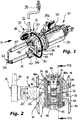
- a welding gun according to a first embodiment of the invention is indicated 10 in its whole.
- the gun 10 which is of the type adapted to be controlled manually by an operator, comprises an intermediate portion provided with a barycentric system allowing it to be supported and articulated, indicated 12 in general.
- the system 12 includes a main bearing 14 adapted to allow the gun 10 to rotate about a longitudinal main axis thereof, which comprises an inner ring 16, forming a main support member of the gun 10, and an outer ring 18.
- the rings 16 and 18 have mutually facing rolling races 22a to allow rotary members, such as balls 22, to slide.
- a cantilever support arm 20 extends radially from the outer ring 18, outwardly from the bearing 14.
- a secondary bearing 24, the axis of which is parallel to the arm 20, is connected to the arm 20 to allow the gun 10 to rotate transversely with respect to its longitudinal axis, according to a pitch movement.
- a S-shaped upright 26 projects radially upwards from the outer ring of the bearing 24, an upper end of which is intended to be connected and articulated in 28 to a overhead suspension device, in a manner known per se.
- a maneuver handwheel 30 fixed to the inner ring of the bearing 14 by connection members 32, as well as a pair of upper and side handles 34a and 34b, respectively.
- the gun 10 is provided with a pair of electrode holder arms, which are movable one with respect to the other, and are provided with respective welding electrodes.
- the gun 10 comprises a lower tubular electrode holder arm 36 provided with an electrode 38, stationary mounted with respect to the inner ring 16 of the bearing 14 by means of a clamp 40.
- the clamp 40 is fixed to a first end of a pair of brackets 42 extending cantilever along a generally tilted direction with respect to the longitudinal axis of the gun 10.
- the brackets 42 are crossed in a middle position by a transverse pin of rotation 44 to which first ends of a pair of L-shaped arms of articulation 46 are pivoted, which are also conveniently of light alloy, outside of the brackets 42.
- a clamp 48 is fixed to the second ends of the arms 46, on the side opposite to the pin 44, in order to allow an upper tubular electrode holder arm 50 to be secured.
- the electrode holder arms 36 and 50 are usually made of copper or relevant alloys, are insulated with respect to the clamps 40 and 48 by respective insulating gaskets (not shown), and are cooled by inner water circulation, in a manner known per se.
- the relative movement of the electrodes 38 and 52 could be of the translational type, in which case the movable electrode 52 is adapted to move along a rectilinear path to-and-from the stationary electrode 38, and has, in this case, a substantially a C-shaped general configuration, according to an arrangement known per se in the art.
- the rear portion of the gun 10 mainly includes a linear actuator 54 intended to control the movement of the movable electrode holder arm 50, and a transformer unit 56 for feeding an electrical welding current to the electrodes 38 and 52, as well as relevant electrical wirings and ducts for flowing service fluids.
- a linear actuator 54 intended to control the movement of the movable electrode holder arm 50
- a transformer unit 56 for feeding an electrical welding current to the electrodes 38 and 52, as well as relevant electrical wirings and ducts for flowing service fluids.
- its rear portion including the actuator 54 and the transformer unit 56 is sheathed by a covering 58 shown in figure 1 .
- the actuator 54 has a body 60 the structure of which comprises a plurality of segments 62 interconnected by screw studs 64, and which is fixed in a manner known per se, typically by means of fastening screws (not shown in detail), to a base plate 66 arranged adjacent to the back face (with reference to the figures) of the inner ring 16 of the bearing 14.
- a pair of symmetrical wings 66a, shaped as circular segments, can be associated to the base plate 66, at opposite sides, in order to make, together with the base plate 66, a member having a substantially circular shape corresponding to that of the ring 16.
- Each bracket 42 bears on the front surface of the inner ring 16 by a respective end foot 42a.
- a pair of adjacent holes are formed in each end foot 42a of the brackets 42, in which respective screws 70 are inserted, said screws crossing also respective through holes 72 of the inner ring 16, and having threaded ends projecting from the ring 16 so as to engage threaded holes 74 of the plate 66.
- the brackets 42 are rigidly connected with the inner ring 16 and with the plate 66 and, through the latter, with the body 60 of the actuator 54 which is arranged adjacent to the rear face of the ring 16, so that the brackets 42 form a single body with the body 60 of the actuator 54 and with the inner ring 16, which performs the function of a main support member for the gun 10.
- auxiliary fixing screws 75 are usually associated to each bracket 42 in order to fix permanently it to the inner ring 16.
- one or more through holes 76 are formed in the ring 16, to allow a respective screw 75 to be inserted, the thread of which engage a threaded hole 78 formed in a base portion of the respective bracket 42, which base portion faces the front face of the ring 16, at the side opposite to the clamp 40.
- the actuator 54 has a slidable stem 80 crossing, with a clearance, a hole 82 formed in the ring 16 in a central position between the holes 72, in such a manner that the stem 80 projects from the front face of the ring 16.
- a transmission unit is fixed to the free end of the stem 80, typically in an axially adjustable manner.
- Such a transmission unit includes a block 84 in which an arched slot 86 is formed, which slot is intended to be slidably engaged by a transverse bar 88, parallel to the pin 44 and connected to both the arms of articulation 46 at through holes 88a formed at position adjacent to their intermediate elbow portions.
- the ring 16 has a through wide opening 90 below the hole 82, close to which, at its rear side, the transformer unit 56 is fixed by fastening means known per se and not shown in detail, for example screws.
- a pair of conductors 92 and 94 extend through the opening 90, which are connected in a manner known per se on the one side with the clamps 40 and 48, and on the other side with the secondary of the transformer 56, respectively, with the aim of feeding with electrical current the electrodes 38 and 52 supported by the arms 36 and 50, at least the conductor 94 being of the flexible type.
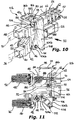
- FIG. 8 to 11 A second embodiment of the invention is shown in figures 8 to 11 , of which figures 8, 9 and 10, 11 refer, respectively, to two modifications of welding guns which are adapted to be suspended to a handling robot arm, for example of the anthropomorhic type so that their movement in the space can be controlled automatically, or, as an alternative, are adapted to be suspended to a stationary column shaped support base, in which case the workpiece to be welded is intended to be moved by a handling apparatus known per se.
- the welding gun here indicated 10a, comprises a frame 96a, preferably made by light alloy members, for supporting the welding equipment that includes the two electrode holder arms 36 as well as the actuator 54 and the transformer unit 56.
- the frame 96a intended to be suspended to the wrist of a robot (not shown) in order to allow the gun 10a to be moved, or to the aforesaid column base, essentially comprises an upper head 98 in which a seat 99 is formed for the engagement of the wrist of the robot or of the support base, and from which a pair of substantially trapezoidal shaped parallel flanks 100, 102, fixed to the opposite side edges of the head 98 by conventional connection means, extend downwards.
- connection means such as fixed joint formations and/or fastening screws, to the opposite side edges of a support plate 16a having a general rectangular shape, the function of which, similarly to that of the ring 16 of the previous embodiment, is to constitute the main support member of the gun 10a.
- the transformer unit 56 is also fixed at a wide opening, which cannot be seen in the drawings but which is quite similar to the opening 90 of the ring 16 of the previous embodiment, on the rear face of the plate 16a, at the side opposite to the electrode holder arms 36 and 50.
- each bracket 42 is fixed to the plate 16a by a pair of screws 70 the threads of which engage threaded holes formed in the base plate 66 of the actuator 54.
- auxiliary screws 75 are provided, which screws cross through holes of the plate 16a in order to engage threaded holes formed on the basis of the brackets 42, in a position adjacent to the plate 16a.
- the transformer unit 56 is fixed in a manner known per se to the plate 16a.
- brackets 42 are rigidly connected to the body 60 of the actuator 54 and to the transformer unit 56 through the plate 16a, the latter carrying out the function of a support member for the gun 10a, and therefore to the frame 96a, in such a manner that the brackets 42 form a single body with the frame 96a.
- the stresses exchanged between the actuator 54 and the electrode holder arms 36 and 50 are transmitted directly through the brackets 42, so that the plate 16a can be relatively thin, to full advantage of the reduction of the overall weight of the gun 10a.
- FIG. 10b a modification of the welding gun of the second embodiment is shown, which is here indicated 10b, in general.
- the clamp 10b comprises a frame 96b, similar to the frame 96a of the previous modification, also intended to be suspended from the wrist of a robot, or from a stationary support base.
- flanks 104, 106 having a general rectangular shape, extend from the upper head 98 of the frame 96b towards the bottom.
- Such flanks have respective front appendages 104a, 106a, at an outer position with respect to the brackets 42, in which the opposite ends of the pin 44 are engaged, as well as respective lower appendages 104b, 106b, at the side opposite to the head 98, to which the opposite ends of a transverse rod 108, parallel to the hinge 44, are fixed.
- a generally rectangular plate 16b is arranged between the flanks 104 and 106, which plate carries out a support function similar to that of the ring 16 of the previous embodiment, that is to constitute the main support member of the gun 10b.
- the plate 16b is slidably mounted with respect to the flanks 104 and 106, owing to the presence of a gap between such flanks and the respective side edges of the plate 16b.
- the two brackets 42 are fixed to the plate 16b by pairs of screws 70 engaging also the base plate 66 of the body 60 of the actuator 54, such brackets 42 being usually connected to the plate 16b also through auxiliary screws 75 crossing the plate 16b and engaging threaded holes formed at the basis of the brackets 42.
- transformer unit 56 is mounted on the rear face of the plate 16b at a wide opening similar to the opening 90 of the ring 16 of the previous embodiment.
- Another transverse rod 110 parallel to the rod 108, has the opposite ends fixed to the two brackets 42, at a substantially intermediate position between the hinge 44 and the plate 16b.
- the body of the auxiliary actuator 112 in a manner known per se, is articulated to the transverse rod 108, and a slidable rod 114, the free end of which is articulated to the transverse rod 110 between the brackets 42, extends from it.
- the auxiliary actuator 112 allows also the whole welding equipment to be kept in a predetermined and repeatable configuration in the space, when it is in a non-operative condition, for example during a step in which the gun 10b is moved, with the electrodes 38 and 52 separated to each other.
- brackets 42 are rigidly connected with the body 60 of the actuator 54 and with the transformer unit 56 through the plate 16b, the latter carrying out the function of a main support member of the gun 10b, and therefore with the frame 96b, in such a manner that the brackets 42 form a single body with the frame 96b.
- the stress exchanged between the actuator 54 and the electrode holder arms 36 and 50 are transmitted directly through the brackets 42, so that the plate 16b can be relatively thin, to full advantage of the reduction of the overall weight of the gun 10b.
- the relative movement of the electrodes 38 and 52 can be of the articulated type, such as described in the first embodiment, or, as an alternative, of the translational type in which the electrode 52 is movable along a rectilinear path to-and-fro the stationary electrode 38 that, in this case, will have a substantially C-shaped general configuration, according to an arrangement known per se in the art.
Landscapes
- Engineering & Computer Science (AREA)
- Mechanical Engineering (AREA)
- Resistance Welding (AREA)
Priority Applications (1)
| Application Number | Priority Date | Filing Date | Title |
|---|---|---|---|
| PL10002343T PL2228162T3 (pl) | 2009-03-10 | 2010-03-08 | Podwieszana rezystancyjna zgrzewarka punktowa |
Applications Claiming Priority (1)
| Application Number | Priority Date | Filing Date | Title |
|---|---|---|---|
| ITTO2009A000177A IT1393436B1 (it) | 2009-03-10 | 2009-03-10 | Pinza di saldatura a punti per resistenza sospendibile. |
Publications (2)
| Publication Number | Publication Date |
|---|---|
| EP2228162A1 EP2228162A1 (en) | 2010-09-15 |
| EP2228162B1 true EP2228162B1 (en) | 2017-08-09 |
Family
ID=41327698
Family Applications (1)
| Application Number | Title | Priority Date | Filing Date |
|---|---|---|---|
| EP10002343.1A Active EP2228162B1 (en) | 2009-03-10 | 2010-03-08 | Suspendable resistance spot welding gun |
Country Status (6)
| Country | Link |
|---|---|
| EP (1) | EP2228162B1 (it) |
| BR (1) | BRPI1000724B1 (it) |
| ES (1) | ES2645347T3 (it) |
| IT (1) | IT1393436B1 (it) |
| PL (1) | PL2228162T3 (it) |
| RU (1) | RU2538447C2 (it) |
Families Citing this family (10)
| Publication number | Priority date | Publication date | Assignee | Title |
|---|---|---|---|---|
| CN102513677A (zh) * | 2011-12-30 | 2012-06-27 | 长城汽车股份有限公司 | 一种四轴联动自动点焊机 |
| RS55828B1 (sr) * | 2012-05-15 | 2017-08-31 | Comau Spa | Glava za električno tačkasto zavarivanje namenjena za primenu sa višeosnim industrijskim robotima sa kućištem i nosećom strukturom; robot koji sadrži tu glavu |
| ITTO20120900A1 (it) * | 2012-10-15 | 2014-04-16 | Kgr Spa | Pinza di saldatura a proiezione per il fissaggio di un pezzo, quale una boccola, su una superficie di un elemento di lamiera, e impianto di saldatura che la comprende. |
| ITTO20130090A1 (it) | 2013-02-04 | 2014-08-05 | Kgr Spa | Attuatore a fluido, particolarmente per controllare il movimento relativo dei bracci portaelettrodo di una pinza di saldatura a punti per resistenza. |
| ITTO20130334A1 (it) * | 2013-04-23 | 2014-10-24 | Kgr Spa | Perfezionamenti relativi alle pinze di saldatura per resistenza sospendibili. |
| JP6240981B2 (ja) * | 2014-05-08 | 2017-12-06 | Smc株式会社 | 溶接ガン |
| CN106974444B (zh) * | 2017-04-24 | 2022-11-08 | 深圳市健坤五金有限公司 | 一种可折叠的自动夹紧支撑座结构 |
| FR3098135B1 (fr) | 2019-07-05 | 2022-05-06 | Psa Automobiles Sa | Dispositif de maintien de pince de soudage par point résistant suspendue |
| CN112355430B (zh) * | 2020-10-29 | 2021-05-11 | 广州腾涟晟建材有限公司 | 一种便捷固定异型钢材的钢材切割装置 |
| CN114101996B (zh) * | 2021-12-07 | 2023-10-31 | 安徽福本机械制造有限公司 | 一种工程机械用发动机舱格栅网焊接装置 |
Family Cites Families (6)
| Publication number | Priority date | Publication date | Assignee | Title |
|---|---|---|---|---|
| SU1016112A1 (ru) * | 1981-06-19 | 1983-05-07 | Ордена Ленина И Ордена Трудового Красного Знамени Институт Электросварки Им.Е.О.Патона | Клещи дл контактной точечной сварки |
| US4684778A (en) * | 1984-04-30 | 1987-08-04 | Cecil Dimitrios G | Resistance spot welding gun and transformer assembly |
| SU1719175A1 (ru) * | 1989-04-18 | 1992-03-15 | Донецкий Филиал Проектного И Конструкторско-Технологического Института "Киевский Проектстроймеханизация" | Машина дл контактной точечной сварки |
| SU1785153A1 (ru) * | 1989-11-29 | 1996-08-27 | Всесоюзный научно-исследовательский, проектно-конструкторский и технологический институт электросварочного оборудования | Подвесная сварочная машина |
| JP3799536B2 (ja) * | 1997-04-28 | 2006-07-19 | Obara株式会社 | ポ―タブルスポットガン用吊り金具取付ベ―ス |
| ITBO20050670A1 (it) * | 2005-11-02 | 2007-05-03 | Tecna Spa | Saldatrice a punti a configurazione variabile |
-
2009
- 2009-03-10 IT ITTO2009A000177A patent/IT1393436B1/it active
-
2010
- 2010-03-08 EP EP10002343.1A patent/EP2228162B1/en active Active
- 2010-03-08 ES ES10002343.1T patent/ES2645347T3/es active Active
- 2010-03-08 PL PL10002343T patent/PL2228162T3/pl unknown
- 2010-03-09 RU RU2010108504/02A patent/RU2538447C2/ru active
- 2010-03-10 BR BRPI1000724-5A patent/BRPI1000724B1/pt active IP Right Grant
Non-Patent Citations (1)
| Title |
|---|
| None * |
Also Published As
| Publication number | Publication date |
|---|---|
| RU2010108504A (ru) | 2011-09-20 |
| BRPI1000724A2 (pt) | 2011-06-21 |
| ITTO20090177A1 (it) | 2010-09-11 |
| RU2538447C2 (ru) | 2015-01-10 |
| ES2645347T3 (es) | 2017-12-05 |
| EP2228162A1 (en) | 2010-09-15 |
| PL2228162T3 (pl) | 2018-01-31 |
| BRPI1000724B1 (pt) | 2017-11-28 |
| IT1393436B1 (it) | 2012-04-20 |
Similar Documents
| Publication | Publication Date | Title |
|---|---|---|
| EP2228162B1 (en) | Suspendable resistance spot welding gun | |
| US9844841B2 (en) | Drop center positioner with multiple rotate modules | |
| JP6696509B2 (ja) | 可動加圧部材を有するスポット溶接電極、及びそれを用いたスポット溶接方法 | |
| KR101796398B1 (ko) | 인다이렉트 스폿 용접 장치 | |
| KR20090071541A (ko) | 유사 프레임, 바람직하게는 동일 프레임을 구비하여 평판들을 고정하는 집게 계열, 및 그러한 계열의 집게들 | |
| CN110899908A (zh) | 一种机器人焊缝跟踪激光视觉检测装置 | |
| KR20100089690A (ko) | 선박조립용 이동식 용접장치 | |
| CN106457448A (zh) | 具有多个臂杆和接头的人体工学焊臂 | |
| US11848526B1 (en) | Portable welding ground clamp attachment systems | |
| JP2005028454A (ja) | 溶接ガン | |
| JPH04266486A (ja) | スポット溶接用トング | |
| DE102017116089B4 (de) | Roboterschweißzange | |
| US7091440B2 (en) | Spot welding assembly | |
| CN220217390U (zh) | 一种自动焊接装置 | |
| JP7306900B2 (ja) | 溶接ガン及び溶接方法 | |
| EP1782909A1 (en) | Spot welder with variable configuration | |
| JP5596658B2 (ja) | スポット溶接装置 | |
| JPH06126446A (ja) | 鉄骨構造物用溶接装置 | |
| JP2002224848A (ja) | ポータブルスポット溶接装置 | |
| CN212191837U (zh) | 一种智能焊接系统 | |
| JPH10235478A (ja) | スポット溶接機保持装置およびスポット溶接装置 | |
| JP3872528B2 (ja) | スポット溶接装置 | |
| KR101257164B1 (ko) | 저항 점용접기의 지그 장치 | |
| JP2020040080A (ja) | スポット溶接機の電極位置調整機構 | |
| CN205496777U (zh) | 一种焊钳本体 |
Legal Events
| Date | Code | Title | Description |
|---|---|---|---|
| PUAI | Public reference made under article 153(3) epc to a published international application that has entered the european phase |
Free format text: ORIGINAL CODE: 0009012 |
|
| AK | Designated contracting states |
Kind code of ref document: A1 Designated state(s): AT BE BG CH CY CZ DE DK EE ES FI FR GB GR HR HU IE IS IT LI LT LU LV MC MK MT NL NO PL PT RO SE SI SK SM TR |
|
| AX | Request for extension of the european patent |
Extension state: AL BA ME RS |
|
| 17P | Request for examination filed |
Effective date: 20110310 |
|
| GRAP | Despatch of communication of intention to grant a patent |
Free format text: ORIGINAL CODE: EPIDOSNIGR1 |
|
| RIC1 | Information provided on ipc code assigned before grant |
Ipc: B23K 11/28 20060101AFI20170215BHEP |
|
| INTG | Intention to grant announced |
Effective date: 20170301 |
|
| GRAS | Grant fee paid |
Free format text: ORIGINAL CODE: EPIDOSNIGR3 |
|
| GRAA | (expected) grant |
Free format text: ORIGINAL CODE: 0009210 |
|
| AK | Designated contracting states |
Kind code of ref document: B1 Designated state(s): AT BE BG CH CY CZ DE DK EE ES FI FR GB GR HR HU IE IS IT LI LT LU LV MC MK MT NL NO PL PT RO SE SI SK SM TR |
|
| REG | Reference to a national code |
Ref country code: GB Ref legal event code: FG4D |
|
| REG | Reference to a national code |
Ref country code: CH Ref legal event code: EP Ref country code: AT Ref legal event code: REF Ref document number: 916291 Country of ref document: AT Kind code of ref document: T Effective date: 20170815 |
|
| REG | Reference to a national code |
Ref country code: DE Ref legal event code: R082 Ref document number: 602010044188 Country of ref document: DE Representative=s name: GUSTORF, GERHARD, DIPL.-ING., DE Ref country code: DE Ref legal event code: R082 Ref document number: 602010044188 Ref country code: DE Ref legal event code: R082 Ref document number: 602010044188 Country of ref document: DE Representative=s name: KUHNEN & WACKER PATENT- UND RECHTSANWALTSBUERO, DE |
|
| REG | Reference to a national code |
Ref country code: IE Ref legal event code: FG4D |
|
| REG | Reference to a national code |
Ref country code: DE Ref legal event code: R096 Ref document number: 602010044188 Country of ref document: DE |
|
| REG | Reference to a national code |
Ref country code: RO Ref legal event code: EPE |
|
| REG | Reference to a national code |
Ref country code: DE Ref legal event code: R082 Ref document number: 602010044188 Country of ref document: DE Representative=s name: KUHNEN & WACKER PATENT- UND RECHTSANWALTSBUERO, DE |
|
| REG | Reference to a national code |
Ref country code: ES Ref legal event code: FG2A Ref document number: 2645347 Country of ref document: ES Kind code of ref document: T3 Effective date: 20171205 |
|
| REG | Reference to a national code |
Ref country code: NL Ref legal event code: MP Effective date: 20170809 |
|
| REG | Reference to a national code |
Ref country code: LT Ref legal event code: MG4D |
|
| PG25 | Lapsed in a contracting state [announced via postgrant information from national office to epo] |
Ref country code: SE Free format text: LAPSE BECAUSE OF FAILURE TO SUBMIT A TRANSLATION OF THE DESCRIPTION OR TO PAY THE FEE WITHIN THE PRESCRIBED TIME-LIMIT Effective date: 20170809 Ref country code: NO Free format text: LAPSE BECAUSE OF FAILURE TO SUBMIT A TRANSLATION OF THE DESCRIPTION OR TO PAY THE FEE WITHIN THE PRESCRIBED TIME-LIMIT Effective date: 20171109 Ref country code: FI Free format text: LAPSE BECAUSE OF FAILURE TO SUBMIT A TRANSLATION OF THE DESCRIPTION OR TO PAY THE FEE WITHIN THE PRESCRIBED TIME-LIMIT Effective date: 20170809 Ref country code: HR Free format text: LAPSE BECAUSE OF FAILURE TO SUBMIT A TRANSLATION OF THE DESCRIPTION OR TO PAY THE FEE WITHIN THE PRESCRIBED TIME-LIMIT Effective date: 20170809 Ref country code: LT Free format text: LAPSE BECAUSE OF FAILURE TO SUBMIT A TRANSLATION OF THE DESCRIPTION OR TO PAY THE FEE WITHIN THE PRESCRIBED TIME-LIMIT Effective date: 20170809 Ref country code: NL Free format text: LAPSE BECAUSE OF FAILURE TO SUBMIT A TRANSLATION OF THE DESCRIPTION OR TO PAY THE FEE WITHIN THE PRESCRIBED TIME-LIMIT Effective date: 20170809 |
|
| PG25 | Lapsed in a contracting state [announced via postgrant information from national office to epo] |
Ref country code: LV Free format text: LAPSE BECAUSE OF FAILURE TO SUBMIT A TRANSLATION OF THE DESCRIPTION OR TO PAY THE FEE WITHIN THE PRESCRIBED TIME-LIMIT Effective date: 20170809 Ref country code: BG Free format text: LAPSE BECAUSE OF FAILURE TO SUBMIT A TRANSLATION OF THE DESCRIPTION OR TO PAY THE FEE WITHIN THE PRESCRIBED TIME-LIMIT Effective date: 20171109 Ref country code: GR Free format text: LAPSE BECAUSE OF FAILURE TO SUBMIT A TRANSLATION OF THE DESCRIPTION OR TO PAY THE FEE WITHIN THE PRESCRIBED TIME-LIMIT Effective date: 20171110 Ref country code: IS Free format text: LAPSE BECAUSE OF FAILURE TO SUBMIT A TRANSLATION OF THE DESCRIPTION OR TO PAY THE FEE WITHIN THE PRESCRIBED TIME-LIMIT Effective date: 20171209 |
|
| REG | Reference to a national code |
Ref country code: FR Ref legal event code: PLFP Year of fee payment: 9 |
|
| PG25 | Lapsed in a contracting state [announced via postgrant information from national office to epo] |
Ref country code: CZ Free format text: LAPSE BECAUSE OF FAILURE TO SUBMIT A TRANSLATION OF THE DESCRIPTION OR TO PAY THE FEE WITHIN THE PRESCRIBED TIME-LIMIT Effective date: 20170809 Ref country code: DK Free format text: LAPSE BECAUSE OF FAILURE TO SUBMIT A TRANSLATION OF THE DESCRIPTION OR TO PAY THE FEE WITHIN THE PRESCRIBED TIME-LIMIT Effective date: 20170809 |
|
| REG | Reference to a national code |
Ref country code: DE Ref legal event code: R097 Ref document number: 602010044188 Country of ref document: DE |
|
| PG25 | Lapsed in a contracting state [announced via postgrant information from national office to epo] |
Ref country code: SM Free format text: LAPSE BECAUSE OF FAILURE TO SUBMIT A TRANSLATION OF THE DESCRIPTION OR TO PAY THE FEE WITHIN THE PRESCRIBED TIME-LIMIT Effective date: 20170809 Ref country code: SK Free format text: LAPSE BECAUSE OF FAILURE TO SUBMIT A TRANSLATION OF THE DESCRIPTION OR TO PAY THE FEE WITHIN THE PRESCRIBED TIME-LIMIT Effective date: 20170809 Ref country code: EE Free format text: LAPSE BECAUSE OF FAILURE TO SUBMIT A TRANSLATION OF THE DESCRIPTION OR TO PAY THE FEE WITHIN THE PRESCRIBED TIME-LIMIT Effective date: 20170809 |
|
| PLBE | No opposition filed within time limit |
Free format text: ORIGINAL CODE: 0009261 |
|
| STAA | Information on the status of an ep patent application or granted ep patent |
Free format text: STATUS: NO OPPOSITION FILED WITHIN TIME LIMIT |
|
| 26N | No opposition filed |
Effective date: 20180511 |
|
| PG25 | Lapsed in a contracting state [announced via postgrant information from national office to epo] |
Ref country code: SI Free format text: LAPSE BECAUSE OF FAILURE TO SUBMIT A TRANSLATION OF THE DESCRIPTION OR TO PAY THE FEE WITHIN THE PRESCRIBED TIME-LIMIT Effective date: 20170809 |
|
| REG | Reference to a national code |
Ref country code: CH Ref legal event code: PL |
|
| PG25 | Lapsed in a contracting state [announced via postgrant information from national office to epo] |
Ref country code: MC Free format text: LAPSE BECAUSE OF FAILURE TO SUBMIT A TRANSLATION OF THE DESCRIPTION OR TO PAY THE FEE WITHIN THE PRESCRIBED TIME-LIMIT Effective date: 20170809 |
|
| REG | Reference to a national code |
Ref country code: BE Ref legal event code: MM Effective date: 20180331 |
|
| REG | Reference to a national code |
Ref country code: IE Ref legal event code: MM4A |
|
| PG25 | Lapsed in a contracting state [announced via postgrant information from national office to epo] |
Ref country code: LU Free format text: LAPSE BECAUSE OF NON-PAYMENT OF DUE FEES Effective date: 20180308 |
|
| PG25 | Lapsed in a contracting state [announced via postgrant information from national office to epo] |
Ref country code: IE Free format text: LAPSE BECAUSE OF NON-PAYMENT OF DUE FEES Effective date: 20180308 |
|
| PG25 | Lapsed in a contracting state [announced via postgrant information from national office to epo] |
Ref country code: BE Free format text: LAPSE BECAUSE OF NON-PAYMENT OF DUE FEES Effective date: 20180331 Ref country code: CH Free format text: LAPSE BECAUSE OF NON-PAYMENT OF DUE FEES Effective date: 20180331 Ref country code: LI Free format text: LAPSE BECAUSE OF NON-PAYMENT OF DUE FEES Effective date: 20180331 |
|
| PG25 | Lapsed in a contracting state [announced via postgrant information from national office to epo] |
Ref country code: MT Free format text: LAPSE BECAUSE OF NON-PAYMENT OF DUE FEES Effective date: 20180308 |
|
| PG25 | Lapsed in a contracting state [announced via postgrant information from national office to epo] |
Ref country code: PT Free format text: LAPSE BECAUSE OF FAILURE TO SUBMIT A TRANSLATION OF THE DESCRIPTION OR TO PAY THE FEE WITHIN THE PRESCRIBED TIME-LIMIT Effective date: 20170809 Ref country code: HU Free format text: LAPSE BECAUSE OF FAILURE TO SUBMIT A TRANSLATION OF THE DESCRIPTION OR TO PAY THE FEE WITHIN THE PRESCRIBED TIME-LIMIT; INVALID AB INITIO Effective date: 20100308 |
|
| PG25 | Lapsed in a contracting state [announced via postgrant information from national office to epo] |
Ref country code: CY Free format text: LAPSE BECAUSE OF FAILURE TO SUBMIT A TRANSLATION OF THE DESCRIPTION OR TO PAY THE FEE WITHIN THE PRESCRIBED TIME-LIMIT Effective date: 20170809 Ref country code: MK Free format text: LAPSE BECAUSE OF NON-PAYMENT OF DUE FEES Effective date: 20170809 |
|
| REG | Reference to a national code |
Ref country code: DE Ref legal event code: R082 Ref document number: 602010044188 Country of ref document: DE Representative=s name: KUHNEN & WACKER PATENT- UND RECHTSANWALTSBUERO, DE |
|
| REG | Reference to a national code |
Ref country code: AT Ref legal event code: UEP Ref document number: 916291 Country of ref document: AT Kind code of ref document: T Effective date: 20170809 |
|
| PGFP | Annual fee paid to national office [announced via postgrant information from national office to epo] |
Ref country code: RO Payment date: 20230307 Year of fee payment: 14 |
|
| P01 | Opt-out of the competence of the unified patent court (upc) registered |
Effective date: 20230603 |
|
| PGFP | Annual fee paid to national office [announced via postgrant information from national office to epo] |
Ref country code: AT Payment date: 20240125 Year of fee payment: 15 |
|
| PGFP | Annual fee paid to national office [announced via postgrant information from national office to epo] |
Ref country code: TR Payment date: 20240125 Year of fee payment: 15 |
|
| PG25 | Lapsed in a contracting state [announced via postgrant information from national office to epo] |
Ref country code: RO Free format text: LAPSE BECAUSE OF NON-PAYMENT OF DUE FEES Effective date: 20240308 |
|
| PGFP | Annual fee paid to national office [announced via postgrant information from national office to epo] |
Ref country code: ES Payment date: 20250404 Year of fee payment: 16 |
|
| REG | Reference to a national code |
Ref country code: AT Ref legal event code: MM01 Ref document number: 916291 Country of ref document: AT Kind code of ref document: T Effective date: 20250308 |
|
| PG25 | Lapsed in a contracting state [announced via postgrant information from national office to epo] |
Ref country code: AT Free format text: LAPSE BECAUSE OF NON-PAYMENT OF DUE FEES Effective date: 20250308 |
|
| PGFP | Annual fee paid to national office [announced via postgrant information from national office to epo] |
Ref country code: FR Payment date: 20251231 Year of fee payment: 17 |
|
| PGFP | Annual fee paid to national office [announced via postgrant information from national office to epo] |
Ref country code: PL Payment date: 20251212 Year of fee payment: 17 |
|
| PGFP | Annual fee paid to national office [announced via postgrant information from national office to epo] |
Ref country code: GB Payment date: 20260106 Year of fee payment: 17 |
|
| PGFP | Annual fee paid to national office [announced via postgrant information from national office to epo] |
Ref country code: DE Payment date: 20260102 Year of fee payment: 17 |
|
| PGFP | Annual fee paid to national office [announced via postgrant information from national office to epo] |
Ref country code: IT Payment date: 20260213 Year of fee payment: 17 |