EP2228295B1 - Rollenbahn - Google Patents
Rollenbahn Download PDFInfo
- Publication number
- EP2228295B1 EP2228295B1 EP10155877.3A EP10155877A EP2228295B1 EP 2228295 B1 EP2228295 B1 EP 2228295B1 EP 10155877 A EP10155877 A EP 10155877A EP 2228295 B1 EP2228295 B1 EP 2228295B1
- Authority
- EP
- European Patent Office
- Prior art keywords
- rail
- roller conveyor
- stabilisation
- floor
- loading plane
- Prior art date
- Legal status (The legal status is an assumption and is not a legal conclusion. Google has not performed a legal analysis and makes no representation as to the accuracy of the status listed.)
- Not-in-force
Links
- 230000006641 stabilisation Effects 0.000 claims description 13
- 229910052751 metal Inorganic materials 0.000 claims description 5
- 239000002184 metal Substances 0.000 claims description 5
- 229920002430 Fibre-reinforced plastic Polymers 0.000 claims description 2
- 229910052782 aluminium Inorganic materials 0.000 claims description 2
- XAGFODPZIPBFFR-UHFFFAOYSA-N aluminium Chemical compound [Al] XAGFODPZIPBFFR-UHFFFAOYSA-N 0.000 claims description 2
- 239000011151 fibre-reinforced plastic Substances 0.000 claims description 2
- 239000000463 material Substances 0.000 claims description 2
- 239000004411 aluminium Substances 0.000 claims 1
- 238000011105 stabilization Methods 0.000 description 7
- 230000000087 stabilizing effect Effects 0.000 description 5
- 238000010276 construction Methods 0.000 description 2
- 230000002093 peripheral effect Effects 0.000 description 2
- 238000005452 bending Methods 0.000 description 1
- 150000001875 compounds Chemical class 0.000 description 1
- 239000004033 plastic Substances 0.000 description 1
- 229920003023 plastic Polymers 0.000 description 1
- 239000003381 stabilizer Substances 0.000 description 1
- 239000004575 stone Substances 0.000 description 1
Images
Classifications
-
- B—PERFORMING OPERATIONS; TRANSPORTING
- B64—AIRCRAFT; AVIATION; COSMONAUTICS
- B64D—EQUIPMENT FOR FITTING IN OR TO AIRCRAFT; FLIGHT SUITS; PARACHUTES; ARRANGEMENT OR MOUNTING OF POWER PLANTS OR PROPULSION TRANSMISSIONS IN AIRCRAFT
- B64D9/00—Equipment for handling freight; Equipment for facilitating passenger embarkation or the like
-
- B—PERFORMING OPERATIONS; TRANSPORTING
- B64—AIRCRAFT; AVIATION; COSMONAUTICS
- B64C—AEROPLANES; HELICOPTERS
- B64C1/00—Fuselages; Constructional features common to fuselages, wings, stabilising surfaces or the like
- B64C1/18—Floors
- B64C1/20—Floors specially adapted for freight
-
- B—PERFORMING OPERATIONS; TRANSPORTING
- B64—AIRCRAFT; AVIATION; COSMONAUTICS
- B64D—EQUIPMENT FOR FITTING IN OR TO AIRCRAFT; FLIGHT SUITS; PARACHUTES; ARRANGEMENT OR MOUNTING OF POWER PLANTS OR PROPULSION TRANSMISSIONS IN AIRCRAFT
- B64D9/00—Equipment for handling freight; Equipment for facilitating passenger embarkation or the like
- B64D2009/006—Rollers or drives for pallets of freight containers, e.g. PDU
Definitions
- the invention relates to a roller conveyor according to the preamble of claim 1.
- a cargo deck for receiving cargo in the hold of an aircraft is known, which is constructed of modules which can be mounted outside of the fuselage and installed in a largely assembled state in the aircraft. These floor modules must be considered both on their own (when installed and installed in the aircraft) as well as later in the aircraft have a high stability.
- roller conveyors which connect cross members of the floor modules together with floor panels.
- the invention is based on the object to show a roller conveyor of the type mentioned in such a way that increased stability of the floor modules is guaranteed.
- the rail has an outer flange, on which the stabilizing element extending obliquely to the loading plane is fastened.
- the roller conveyor or the rail is mounted on the edge of the floor module. This stabilization element thus gives the roller conveyor increased rigidity, which in turn makes the floor modules "firmer”.
- the stabilization element comprises a stabilization bar provided with a stop area, which is at least partially higher than the upper edges of the rail relative to the loading plane.
- a stop for displaced on the roller conveyor loads is achieved at the same time. It will be here so "two birds with one stone” beaten.
- the stabilizing element may further comprise a bent sheet metal element, which is firmly connected to the rail.
- a sheet metal element has a low weight, but additionally increases the flexural rigidity of the rail.
- a cover of the edge regions between the floor modules and the fuselage is ensured, so that here again a multi-functionality is ensured.
- the rail is preferably made as an extruded profile, in particular made of aluminum. This is inexpensive.
- the stop bar is preferably made of fiber-reinforced plastic.
- a high strength is achieved at relatively low weight
- a sufficiently high wear resistance is given, which is useful for such a stop.
- such materials also have relatively low coefficients of friction, as is advantageous when a container is moved in the hold under attack on the stop bar.
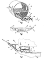
- Fig. 2 is a part of a fuselage with a ground module shown, as shown in the EP 1 646 556 B1 is known.
- a floor module 20 has cross members 30, which are connected to one another via roller conveyors 23 and edge roller conveyors or rails 40.
- floor panels 22 are provided, which are mounted between the roller conveyors 23 and 40 and the cross members 30, so that a walk-in surface is formed.
- the panels 22 and the surface of the floor module 20 forms a loading plane in the XY direction, as in Fig. 2 is indicated with a coordinate system.
- Such floor modules 20 may be mounted outside of an aircraft fuselage 10 having an upper portion 8 and a lower portion 9 in which a cargo space is formed.
- the floor modules 20 are attached to end portions of the cross members 30 to frames 11 as shown in FIGS FIGS. 2 and 3 is shown. End portions 33, 33 'of the cross member 30 are also on the frames 11 and on an outer skin 12 of the fuselage 10th fastened when the floor module 30 is installed after its (taking place outside of the fuselage) assembly in the fuselage.
- the rail 40 which forms a peripheral roller conveyor, constructed such that between side cheeks 41, 42 which extend in the XZ direction, rollers 24 are rotatably mounted such that its outer periphery on upper edges 49, 49 'of the rail 40th protrude.
- the side cheeks 41, 42 are interconnected by a bottom portion 43 having a kink portion 46.
- the kink region 46 connects a higher section 44 with a lower section 45 (seen relative to the upper edges 49, 49 'or to the loading plane XY), so that this kinked area 46 in FIG Fig. 1 from top left to bottom right.
- the rail 40 is given increased stability in the longitudinal direction.
- the rail 40 is further provided with an inner flange 48 which serves to support and secure the floor panels 22.
- a plate member 63 is fixedly mounted, which is also inclined from top left to bottom right.
- the rail 40 is at several locations in Fig. 1 are shown schematically by lines with thickened end points, connected to the cross member 30. These are preferably screwed or riveted joints. Such compounds also fix the sheet 63 on the outer flange 47 of the rail 40 and connect the plate 63 with the end portion 33 of the cross member 30th
- a stabilizing strip 61 is provided, which is designed as a plastic hollow profile and is connected together with the plate 63 with the end portion 33 of the cross member 30.
- this stabilizer bar 61 forms, together with the sheet metal element 63 and the connection with the outer flange 47 to the rail 40, a further stabilizing element 60 for the rail 40 or for the entire floor module 20.
- the stabilization strip 61 has a stop region 62 which lies above the upper edges 49, 49 'of the rail 40.
- a particularly rigid bottom module 20 is created by a combination of individual components and their special construction.
Landscapes
- Engineering & Computer Science (AREA)
- Aviation & Aerospace Engineering (AREA)
- Mechanical Engineering (AREA)
- Rollers For Roller Conveyors For Transfer (AREA)
- Connection Of Plates (AREA)
Description
- Die Erfindung betrifft eine Rollenbahn nach dem Oberbegriff des Patentanspruches 1.
- Aus der
EP 1 646 556 B1 und aus derEP 1 646 557 B1 ist ein Frachtdeck zur Aufnahme von Ladung im Frachtraum eines Flugzeugs bekannt, das aus Modulen aufgebaut ist, welche außerhalb des Flugzeugrumpfes montiert und in einem zum großen Teil fertig montierten Zustand in das Flugzeug eingebaut werden können. Diese Bodenmodule müssen sowohl für sich alleine gesehen (bei Montage und Einbau in das Flugzeug) als auch später im Flugzeug eine hohe Stabilität aufweisen. - Einen wesentlichen Anteil an der Stabilität haben Rollenbahnen, welche Querträger der Bodenmodule zusammen mit Bodenpanelen verbinden.
- Aus der
US 3 915 275 , die als nächstliegender Stand der Technik betrochtet wird, A ist eine Rollenbahn bekannt, deren Boden zweifach geknickt ist. Dadurch wird eine erhöhte Stabilität erzielt. Diese genügt jedoch für den Anwendungszweck als Rollenbahn eines Bodenmoduls noch nicht. - Der Erfindung liegt die Aufgabe zu Grunde, eine Rollenbahn der eingangs genannten Art dahin gehend aufzuzeigen, dass eine erhöhte Stabilität der Bodenmodule gewährleistet ist.
- Diese Aufgabe wird durch eine Rollenbahn nach Patentanspruch 1 gelöst.
- Insbesondere wird die Aufgabe durch eine Rollenbahn mit einem Stabilisationselement bei einem Bodenmodul eines Bodenmoduls eines Flugzeug-Frachtraumbodens gelöst, der eine Ladeebene (X, Y) definiert, wobei das Bodenmodul Querträger aufweist, an denen die Rollenbahn befestigt werden kann, umfassend eine Schiene mit zwei Seitenwangen, zwischen denen Rollen drehbar derart gelagert sind, dass sie über Oberränder der Schiene herausragen, und einen, die Seitenwangen verbindenden Bodenabschnitt, wobei der Bodenabschnitt einen im Querschnitt schräg zur Ladeebene (X, Y) geneigten Knickbereich aufweist, der den Bodenabschnitt in einen höheren und einen niedrigeren relativ zu den Oberrändern liegenden Teilabschnitt unterteilt. Hierbei weist die Schiene einen Außenflansch auf, an welchem das zur Ladeebene schräg verlaufende Stabilisationselement befestigt ist. In diesem Fall ist also die Rollenbahn bzw. die Schiene am Rand des Bodenmoduls montiert. Dieses Stabilisationselement verleiht somit der Rollenbahn eine erhöhte Steifigkeit, was die Bodenmodule wiederum "fester" macht.
- Wenn die Rollenbahn am Rand des Bodenmoduls montiert ist, so ist es von Vorteil, wenn das Stabilisationselement eine mit einem Anschlagbereich versehene Stabilisationsleiste umfasst, die relativ zur Ladeebene mindestens abschnittsweise höher ist als die Oberränder der Schiene. Einerseits wird dadurch wiederum eine Erhöhung der Biegesteifigkeit erzielt, andererseits wird gleichzeitig ein Anschlag für auf der Rollenbahn verschobene Lasten (Container) erzielt. Es werden also hier gleich "zwei Fliegen mit einer Klappe geschlagen".
- Das Stabilisationselement kann weiterhin ein gebogenes Blechelement umfassen, welches mit der Schiene fest verbunden ist. Ein solches Blechelement weist ein geringes Gewicht auf, erhöht jedoch die Biegesteifigkeit der Schiene zusätzlich. Darüber hinaus wird auch gleichzeitig eine Abdeckung der Randbereiche zwischen den Bodenmodulen und dem Flugzeugrumpf sichergestellt, so dass auch hier wieder eine Mehrfunktionalität gewährleistet ist.
- Die Schiene wird vorzugsweise als Strangpressprofil, insbesondere aus Aluminium gefertigt. Dies ist kostengünstig.
- Die Anschlagleiste wiederum ist vorzugsweise aus faserverstärktem Kunststoff gefertigt. Dadurch wird bei relativ niedrigem Gewicht einerseits eine hohe Festigkeit erzielt, andererseits ist auch eine hinreichend hohe Verschleißfestigkeit gegeben, welche für einen derartigen Anschlag sinnvoll ist. Schließlich weisen derartige Materialien auch relativ niedrige Reibungskoeffizienten auf, wie dies vorteilhaft ist, wenn ein Container im Laderaum unter Anschlag an der Anschlagleiste verschoben wird.
- Nachfolgend wird die Erfindung anhand eines Ausführungsbeispiels näher erläutert, das in den beiliegenden Zeichnungen gezeigt ist. Hierbei zeigen
- - Fig. 1
- Einen Querschnitt durch eine Rollenbahn mit Stabilisationselement gemäß einer Ausführungsform der Erfindung,
- - Fig. 2
- eine perspektivische Darstellung eines Flugzeugrumpf-Abschnittes mit einem Bodenmodul und
- - Fig. 3
- eine Teil-Draufsicht auf ein Bodenmodul mit dazu gehörigem Rumpf-Abschnitt.
- In der nachfolgenden Beschreibung werden für gleiche und gleich wirkende Teile dieselben Bezugsziffern verwendet.
- In
Fig. 2 ist ein Teil eines Flugzeugrumpfes mit einem Bodenmodul gezeigt, wie dies aus derEP 1 646 556 B1 bekannt ist. Ein solches Bodenmodul 20 weist Querträger 30 auf, welche über Rollenbahnen 23 sowie randseitige Rollenbahnen bzw. Schienen 40 miteinander verbunden sind. Es sind weiterhin Bodenpaneele 22 vorgesehen, die zwischen den Rollenbahnen 23 bzw. 40 und den Querträgern 30 montiert sind, so dass eine begehbare Fläche entsteht. Die Paneele 22 bzw. die Oberfläche des Bodenmoduls 20 bildet eine Ladeebene in X-Y-Richtung, wie dies inFig. 2 mit einem Koordinatensystem angedeutet ist. Derartige Bodenmodule 20 können außerhalb eines Flugzeugrumpfes 10 montiert werden, der einen oberen Abschnitt 8 und einen unteren Abschnitt 9 aufweist, in welchem ein Frachtraum gebildet ist. - Die Bodenmodule 20 werden mit Endabschnitten der Querträger 30 an Spanten 11 befestigt, wie dies in den
Fig. 2 und 3 gezeigt ist. Endabschnitte 33, 33' der Querträger 30 werden ebenfalls an den Spanten 11 bzw. an einer Außenhaut 12 des Rumpfes 10 befestigt, wenn das Bodenmodul 30 nach seiner (außerhalb des Flugzeugrumpfes stattfindenden) Montage in den Flugzeugrumpf eingebaut wird. - Wie in
Fig. 1 dargestellt, ist die Schiene 40, welche eine randseitige Rollenbahn bildet, derart aufgebaut, dass zwischen Seitenwangen 41, 42, die sich in X-Z-Richtung erstrecken, Rollen 24 derart drehbeweglich gelagert sind, dass ihr Außenumfang über Oberränder 49, 49' der Schiene 40 hervorstehen. - Die Seitenwangen 41, 42 sind durch einen Bodenabschnitt 43 miteinander verbunden, der einen Knickbereich 46 aufweist. Der Knickbereich 46 verbindet einen höheren Teilabschnitt 44 mit einem niedrigeren Teilabschnitt 45 (relativ zu den Oberrändern 49, 49' bzw. zur Ladeebene X-Y gesehen), so dass dieser Knickbereich 46 in
Fig. 1 von links oben nach rechts unten verläuft. Durch diesen Knickbereich erhält die Schiene 40 eine erhöhte Stabilität in Längsrichtung. - Die Schiene 40 ist weiterhin mit einem Innenflansch 48 versehen, der zur Auflage und Befestigung der Bodenpaneele 22 dient.
- An einem Außenflansch 47 der Schiene 40 ist ein Blechelement 63 fest angebracht, das ebenfalls von links oben nach rechts unten geneigt verläuft.
- Die Schiene 40 ist an mehreren Stellen, die in
Fig. 1 durch Linien mit verdickten Endpunkten schematisiert dargestellt sind, mit dem Querträger 30 verbunden. Dies sind vorzugsweise Schraub- oder Nietverbindungen. Derartige Verbindungen fixieren auch das Blech 63 am Außenflansch 47 der Schiene 40 und verbinden das Blech 63 mit dem Endabschnitt 33 des Querträgers 30. - Weiter ist eine Stabilisationsleiste 61 vorgesehen, die als Kunststoff-Hohlprofil ausgebildet ist und zusammen mit dem Blech 63 mit dem Endabschnitt 33 des Querträgers 30 verbunden ist. Somit bildet diese Stabilisationsleiste 61 zusammen mit dem Blechelement 63 und der Verbindung mit dem Außenflansch 47 zur Schiene 40 ein weiteres Stabilisationselement 60 für die Schiene 40 bzw. für das gesamte Bodenmodul 20.
- Die Stabilisationsleiste 61 weist einen Anschlagbereich 62 auf, der oberhalb der Oberränder 49, 49' der Schiene 40 liegt. Dadurch können Container 1, welche auf den Rollen 24 verschoben werden, mit ihrem Außenrand am Anschlagbereich 62 entlang gleitend verschoben werden. An dieser Stelle sei bemerkt, dass der Container 1 lediglich schematisiert dargestellt ist, seine übliche spezielle Konstruktion mit einem umlaufenden Außenflansch ist nicht dargestellt.
- Aus Obigem geht hervor, dass mit der vorliegenden Erfindung durch eine Kombination von Einzelbauelementen und deren spezieller Konstruktion ein besonders biegesteifes Bodenmodul 20 geschaffen wird.
-
- 8
- oberer Abschnitt
- 9
- unter Abschnitt
- 10
- Flugzeugrumpf
- 11
- Spanten
- 12
- Außenhaut
- 20
- Bodenmodul
- 22
- Bodenpaneel
- 23
- Rollenbahn
- 24
- Rolle
- 30
- Querträger
- 31
- Stütze
- 32
- Stütze
- 33, 33'
- Endabschnitt
- 40
- Schiene
- 41
- Seitenwange
- 42
- Seitenwange
- 43
- Bodenabschnitt
- 44
- höherer Teilabschnitt
- 45
- niedrigerer Teilabschnitt
- 46
- Knickbereich
- 47
- Außenflansch
- 48
- Innenflansch
- 49, 49'
- Oberrand
- 60
- Stabilisationselement
- 61
- Stabilisationsleiste
- 62
- Anschlagbereich
- 63
- Blechelement
Claims (5)
- Rollenbahn mit einem Stabilisationselement (60) bei einem Bodenmodul (20) eines Flugzeug-Frachtraumbodens, der eine Ladeebene (X, Y) definiert, wobei das Bodenmodul (20) Querträger (30) aufweist, an denen die Rollenbahn befestigt werden kann, umfassend
eine Schiene (40) mit zwei Seitenwangen (41, 42), zwischen denen Rollen (24) drehbar derart gelagert sind, dass sie über Oberränder (49, 49') der Schiene (40) hinausragen, und einen, die Seitenwangen (41, 42) verbindenden Bodenabschnitt (43), wobei der Bodenabschnitt (43) einen im Querschnitt schräg zur Ladeebene (X, Y) geneigten Knickbereich (46) aufweist, der den Bodenabschnitt (43) in einen höheren (44) und einen niedrigeren (44') relativ zu den Oberrändern (49, 49') liegenden Teilabschnitt (45) unterteilt,
dadurch gekennzeichnet, dass
die Schiene (40) einen Außenflansch (47) aufweist, an welchem das zur Ladeebene (X, Y) schräg verlaufende Stabilisationselement (60) befestigt ist. - Rollenbahn nach einem der vorhergehenden Ansprüche, insbesondere nach Anspruch 1,
dadurch gekennzeichnet, dass
das Stabilisationselement (60) eine mit einem Anschlagbereich (62) versehene Stabilisationsleiste (61) umfasst, die relativ zur Ladeebene (X, Y) mindestens abschnittsweise höher als die Oberränder (49, 49') der Schiene (40) angeordnet ist. - Rollenbahn nach einem der vorhergehenden Ansprüche,
dadurch gekennzeichnet, dass
das Stabilisationselement (60) ein gebogenes Blechelement (63) umfasst, welches mit der Schiene (40) fest verbunden ist. - Rollenbahn nach einem der vorhergehenden Ansprüche,
dadurch gekennzeichnet, dass
die Schiene (40) als Strangpressprofil, insbesondere aus Aluminium gefertigt ist. - Rollenbahn nach Anspruch 2,
dadurch gekennzeichnet, dass
die Stabilisationsleiste (61) aus einem faserverstärkten Kunststoff gefertigt ist.
Applications Claiming Priority (1)
| Application Number | Priority Date | Filing Date | Title |
|---|---|---|---|
| DE102009012426A DE102009012426A1 (de) | 2009-03-10 | 2009-03-10 | Rollenbahn |
Publications (3)
| Publication Number | Publication Date |
|---|---|
| EP2228295A2 EP2228295A2 (de) | 2010-09-15 |
| EP2228295A3 EP2228295A3 (de) | 2010-11-17 |
| EP2228295B1 true EP2228295B1 (de) | 2013-05-15 |
Family
ID=42272474
Family Applications (1)
| Application Number | Title | Priority Date | Filing Date |
|---|---|---|---|
| EP10155877.3A Not-in-force EP2228295B1 (de) | 2009-03-10 | 2010-03-09 | Rollenbahn |
Country Status (3)
| Country | Link |
|---|---|
| US (1) | US8714490B2 (de) |
| EP (1) | EP2228295B1 (de) |
| DE (1) | DE102009012426A1 (de) |
Families Citing this family (6)
| Publication number | Priority date | Publication date | Assignee | Title |
|---|---|---|---|---|
| FR2979896A1 (fr) * | 2011-09-08 | 2013-03-15 | Airbus Operations Sas | Element de cadre de fuselage d'aeronef |
| US10773784B2 (en) | 2015-03-20 | 2020-09-15 | Telair International Gmbh | Floor module of an aircraft cargo hold |
| DE102015117571B3 (de) * | 2015-10-15 | 2016-12-01 | Telair International Gmbh | Bodenmodul eines Flugzeugfrachtraumes |
| DE102015104230B4 (de) | 2015-03-20 | 2017-07-13 | Telair International Gmbh | Montageeinrichtung |
| CN106114867B (zh) * | 2016-07-28 | 2019-12-27 | 顺丰科技有限公司 | 无人机货舱 |
| US20240217637A1 (en) * | 2021-06-02 | 2024-07-04 | Bae Systems Plc | Watercraft system |
Family Cites Families (11)
| Publication number | Priority date | Publication date | Assignee | Title |
|---|---|---|---|---|
| DE1060264B (de) * | 1957-09-18 | 1959-06-25 | Iaweseria Flugzeugbau Ges Mit | Ausbildung des Rumpfbodens von Grossflugzeugen, insbesondere Lastflugzeugen |
| US3203527A (en) * | 1962-10-26 | 1965-08-31 | Aircraft cargo handling system | |
| US3357372A (en) * | 1963-07-02 | 1967-12-12 | Mc Donnell Douglas Corp | Cargo handling system |
| NL7408031A (nl) | 1973-08-27 | 1975-03-03 | Masyc Ag | Assortiment, groep of set bouwelementen voor het vervaardigen van transportinrichtingen. |
| US4077590A (en) * | 1976-03-11 | 1978-03-07 | The Boeing Company | Integrated treadway cargo handling system |
| US4039163A (en) * | 1976-04-05 | 1977-08-02 | The Boeing Company | Aircraft cargo ramp |
| US4395172A (en) * | 1980-12-12 | 1983-07-26 | The Boeing Company | Cargo restraint system with spring fuse |
| DE19812014C1 (de) | 1998-03-19 | 1999-08-19 | Daimler Chrysler Aerospace | Riegelelement zum Arretieren von Frachtgütern innerhalb eines Frachtladesystems, insbesondere in einem Flugzeug |
| DE10043180B4 (de) | 2000-08-11 | 2005-08-25 | Telair International Gmbh | Frachtladesystem |
| EP1646556B1 (de) | 2003-07-18 | 2007-06-27 | Telair International GmbH | Frachtdeck zur aufnahme von ladung im frachtraum eines flugzeugs |
| US7748510B2 (en) * | 2007-02-27 | 2010-07-06 | The Boeing Company | Torque tube apparatus for moving cargo |
-
2009
- 2009-03-10 DE DE102009012426A patent/DE102009012426A1/de not_active Ceased
-
2010
- 2010-03-09 EP EP10155877.3A patent/EP2228295B1/de not_active Not-in-force
- 2010-03-10 US US12/721,468 patent/US8714490B2/en not_active Expired - Fee Related
Also Published As
| Publication number | Publication date |
|---|---|
| DE102009012426A1 (de) | 2010-09-16 |
| US8714490B2 (en) | 2014-05-06 |
| EP2228295A2 (de) | 2010-09-15 |
| EP2228295A3 (de) | 2010-11-17 |
| US20100230545A1 (en) | 2010-09-16 |
Similar Documents
| Publication | Publication Date | Title |
|---|---|---|
| EP2195234A1 (de) | STRUKTURBAUTEIL UND VERFAHREN ZUM VERSTEIFEN EINER AUßENHAUT | |
| WO2016150891A1 (de) | Bodenmodul eines flugzeugfrachtraumes | |
| EP2228295A2 (de) | Rollenbahn | |
| EP2508407B1 (de) | Gerüst, insbesondere für elektrische Einrichtungen in einem Schienenfahrzeug, und Verfahren zur Herstellung des Gerüsts | |
| EP2187146B1 (de) | Traganordnung | |
| EP2420406B1 (de) | Vorrichtung zum Sichern von Ladung auf einer Ladefläche eines Fahrzeugaufbaus | |
| DE102005060480B4 (de) | Kraftfahrzeugsitz | |
| EP2324732A1 (de) | Lagerregal, insbesondere automatisches Kleinteilelager | |
| DE102015117571B3 (de) | Bodenmodul eines Flugzeugfrachtraumes | |
| DE102016115081B4 (de) | Verladeklappenvorrichtung für Tiertransportfahrzeuge | |
| DE102015103226B4 (de) | Längsträger für ein Kraftfahrzeug | |
| EP3129285B1 (de) | Flugzeugsitzrahmenvorrichtung | |
| DE102012006387B4 (de) | Verdeckgestell für einen Planenaufbau sowie Schiebestrebe | |
| EP2921631B1 (de) | Bodenschwelle | |
| EP2945827B1 (de) | Montagevorrichtung für ein seitenwandverkleidungselement eines schienenfahrzeugs | |
| DE202021004415U1 (de) | Heckträger | |
| DE3318174C2 (de) | ||
| DE102012106974B4 (de) | Dachanordnung und Verfahren zur Montage einer Dachanordnung für ein Cabriolet-Fahrzeug | |
| DE102021120323B4 (de) | Endseitig einseitig abgestützter Ausleger für ein Kabeltragsystem | |
| DE102012110685A1 (de) | Fensterrahmenstütze | |
| DE102014007165A1 (de) | Sitzquerträger für eine Personenkraftwagenkarosserie | |
| EP4145651B1 (de) | Endseitig einseitig abgestützter ausleger für ein kabeltragsystem | |
| DE2933915A1 (de) | Dachgebaecktraeger fuer kraftfahrzeuge. | |
| DE102008021726B4 (de) | Ladebordwand | |
| EP1889742A2 (de) | Element zur Befestigung des Tanks an der Karosserie eines Kraftfahrzeuges |
Legal Events
| Date | Code | Title | Description |
|---|---|---|---|
| PUAI | Public reference made under article 153(3) epc to a published international application that has entered the european phase |
Free format text: ORIGINAL CODE: 0009012 |
|
| AK | Designated contracting states |
Kind code of ref document: A2 Designated state(s): AT BE BG CH CY CZ DE DK EE ES FI FR GB GR HR HU IE IS IT LI LT LU LV MC MK MT NL NO PL PT RO SE SI SK SM TR |
|
| AX | Request for extension of the european patent |
Extension state: AL BA ME RS |
|
| PUAL | Search report despatched |
Free format text: ORIGINAL CODE: 0009013 |
|
| AK | Designated contracting states |
Kind code of ref document: A3 Designated state(s): AT BE BG CH CY CZ DE DK EE ES FI FR GB GR HR HU IE IS IT LI LT LU LV MC MK MT NL NO PL PT RO SE SI SK SM TR |
|
| AX | Request for extension of the european patent |
Extension state: AL BA ME RS |
|
| 17P | Request for examination filed |
Effective date: 20110321 |
|
| 17Q | First examination report despatched |
Effective date: 20120321 |
|
| GRAP | Despatch of communication of intention to grant a patent |
Free format text: ORIGINAL CODE: EPIDOSNIGR1 |
|
| GRAS | Grant fee paid |
Free format text: ORIGINAL CODE: EPIDOSNIGR3 |
|
| GRAA | (expected) grant |
Free format text: ORIGINAL CODE: 0009210 |
|
| AK | Designated contracting states |
Kind code of ref document: B1 Designated state(s): AT BE BG CH CY CZ DE DK EE ES FI FR GB GR HR HU IE IS IT LI LT LU LV MC MK MT NL NO PL PT RO SE SI SK SM TR |
|
| REG | Reference to a national code |
Ref country code: GB Ref legal event code: FG4D Free format text: NOT ENGLISH Ref country code: CH Ref legal event code: EP |
|
| REG | Reference to a national code |
Ref country code: AT Ref legal event code: REF Ref document number: 612008 Country of ref document: AT Kind code of ref document: T Effective date: 20130615 |
|
| REG | Reference to a national code |
Ref country code: IE Ref legal event code: FG4D Free format text: LANGUAGE OF EP DOCUMENT: GERMAN |
|
| REG | Reference to a national code |
Ref country code: DE Ref legal event code: R096 Ref document number: 502010003325 Country of ref document: DE Effective date: 20130711 |
|
| REG | Reference to a national code |
Ref country code: LT Ref legal event code: MG4D |
|
| REG | Reference to a national code |
Ref country code: NL Ref legal event code: VDEP Effective date: 20130515 |
|
| PG25 | Lapsed in a contracting state [announced via postgrant information from national office to epo] |
Ref country code: LT Free format text: LAPSE BECAUSE OF FAILURE TO SUBMIT A TRANSLATION OF THE DESCRIPTION OR TO PAY THE FEE WITHIN THE PRESCRIBED TIME-LIMIT Effective date: 20130515 Ref country code: FI Free format text: LAPSE BECAUSE OF FAILURE TO SUBMIT A TRANSLATION OF THE DESCRIPTION OR TO PAY THE FEE WITHIN THE PRESCRIBED TIME-LIMIT Effective date: 20130515 Ref country code: ES Free format text: LAPSE BECAUSE OF FAILURE TO SUBMIT A TRANSLATION OF THE DESCRIPTION OR TO PAY THE FEE WITHIN THE PRESCRIBED TIME-LIMIT Effective date: 20130826 Ref country code: PT Free format text: LAPSE BECAUSE OF FAILURE TO SUBMIT A TRANSLATION OF THE DESCRIPTION OR TO PAY THE FEE WITHIN THE PRESCRIBED TIME-LIMIT Effective date: 20130916 Ref country code: SE Free format text: LAPSE BECAUSE OF FAILURE TO SUBMIT A TRANSLATION OF THE DESCRIPTION OR TO PAY THE FEE WITHIN THE PRESCRIBED TIME-LIMIT Effective date: 20130515 Ref country code: NO Free format text: LAPSE BECAUSE OF FAILURE TO SUBMIT A TRANSLATION OF THE DESCRIPTION OR TO PAY THE FEE WITHIN THE PRESCRIBED TIME-LIMIT Effective date: 20130815 Ref country code: IS Free format text: LAPSE BECAUSE OF FAILURE TO SUBMIT A TRANSLATION OF THE DESCRIPTION OR TO PAY THE FEE WITHIN THE PRESCRIBED TIME-LIMIT Effective date: 20130915 Ref country code: GR Free format text: LAPSE BECAUSE OF FAILURE TO SUBMIT A TRANSLATION OF THE DESCRIPTION OR TO PAY THE FEE WITHIN THE PRESCRIBED TIME-LIMIT Effective date: 20130816 Ref country code: SI Free format text: LAPSE BECAUSE OF FAILURE TO SUBMIT A TRANSLATION OF THE DESCRIPTION OR TO PAY THE FEE WITHIN THE PRESCRIBED TIME-LIMIT Effective date: 20130515 |
|
| PG25 | Lapsed in a contracting state [announced via postgrant information from national office to epo] |
Ref country code: HR Free format text: LAPSE BECAUSE OF FAILURE TO SUBMIT A TRANSLATION OF THE DESCRIPTION OR TO PAY THE FEE WITHIN THE PRESCRIBED TIME-LIMIT Effective date: 20130515 Ref country code: PL Free format text: LAPSE BECAUSE OF FAILURE TO SUBMIT A TRANSLATION OF THE DESCRIPTION OR TO PAY THE FEE WITHIN THE PRESCRIBED TIME-LIMIT Effective date: 20130515 Ref country code: BG Free format text: LAPSE BECAUSE OF FAILURE TO SUBMIT A TRANSLATION OF THE DESCRIPTION OR TO PAY THE FEE WITHIN THE PRESCRIBED TIME-LIMIT Effective date: 20130815 |
|
| PG25 | Lapsed in a contracting state [announced via postgrant information from national office to epo] |
Ref country code: LV Free format text: LAPSE BECAUSE OF FAILURE TO SUBMIT A TRANSLATION OF THE DESCRIPTION OR TO PAY THE FEE WITHIN THE PRESCRIBED TIME-LIMIT Effective date: 20130515 |
|
| PG25 | Lapsed in a contracting state [announced via postgrant information from national office to epo] |
Ref country code: CZ Free format text: LAPSE BECAUSE OF FAILURE TO SUBMIT A TRANSLATION OF THE DESCRIPTION OR TO PAY THE FEE WITHIN THE PRESCRIBED TIME-LIMIT Effective date: 20130515 Ref country code: SK Free format text: LAPSE BECAUSE OF FAILURE TO SUBMIT A TRANSLATION OF THE DESCRIPTION OR TO PAY THE FEE WITHIN THE PRESCRIBED TIME-LIMIT Effective date: 20130515 Ref country code: EE Free format text: LAPSE BECAUSE OF FAILURE TO SUBMIT A TRANSLATION OF THE DESCRIPTION OR TO PAY THE FEE WITHIN THE PRESCRIBED TIME-LIMIT Effective date: 20130515 Ref country code: DK Free format text: LAPSE BECAUSE OF FAILURE TO SUBMIT A TRANSLATION OF THE DESCRIPTION OR TO PAY THE FEE WITHIN THE PRESCRIBED TIME-LIMIT Effective date: 20130515 |
|
| PG25 | Lapsed in a contracting state [announced via postgrant information from national office to epo] |
Ref country code: NL Free format text: LAPSE BECAUSE OF FAILURE TO SUBMIT A TRANSLATION OF THE DESCRIPTION OR TO PAY THE FEE WITHIN THE PRESCRIBED TIME-LIMIT Effective date: 20130515 Ref country code: IT Free format text: LAPSE BECAUSE OF FAILURE TO SUBMIT A TRANSLATION OF THE DESCRIPTION OR TO PAY THE FEE WITHIN THE PRESCRIBED TIME-LIMIT Effective date: 20130515 Ref country code: RO Free format text: LAPSE BECAUSE OF FAILURE TO SUBMIT A TRANSLATION OF THE DESCRIPTION OR TO PAY THE FEE WITHIN THE PRESCRIBED TIME-LIMIT Effective date: 20130515 |
|
| PLBE | No opposition filed within time limit |
Free format text: ORIGINAL CODE: 0009261 |
|
| STAA | Information on the status of an ep patent application or granted ep patent |
Free format text: STATUS: NO OPPOSITION FILED WITHIN TIME LIMIT |
|
| 26N | No opposition filed |
Effective date: 20140218 |
|
| REG | Reference to a national code |
Ref country code: DE Ref legal event code: R097 Ref document number: 502010003325 Country of ref document: DE Effective date: 20140218 |
|
| PG25 | Lapsed in a contracting state [announced via postgrant information from national office to epo] |
Ref country code: LU Free format text: LAPSE BECAUSE OF FAILURE TO SUBMIT A TRANSLATION OF THE DESCRIPTION OR TO PAY THE FEE WITHIN THE PRESCRIBED TIME-LIMIT Effective date: 20140309 |
|
| REG | Reference to a national code |
Ref country code: CH Ref legal event code: PL |
|
| REG | Reference to a national code |
Ref country code: IE Ref legal event code: MM4A |
|
| PG25 | Lapsed in a contracting state [announced via postgrant information from national office to epo] |
Ref country code: IE Free format text: LAPSE BECAUSE OF NON-PAYMENT OF DUE FEES Effective date: 20140309 Ref country code: CH Free format text: LAPSE BECAUSE OF NON-PAYMENT OF DUE FEES Effective date: 20140331 Ref country code: LI Free format text: LAPSE BECAUSE OF NON-PAYMENT OF DUE FEES Effective date: 20140331 |
|
| PG25 | Lapsed in a contracting state [announced via postgrant information from national office to epo] |
Ref country code: MT Free format text: LAPSE BECAUSE OF FAILURE TO SUBMIT A TRANSLATION OF THE DESCRIPTION OR TO PAY THE FEE WITHIN THE PRESCRIBED TIME-LIMIT Effective date: 20130515 |
|
| REG | Reference to a national code |
Ref country code: FR Ref legal event code: PLFP Year of fee payment: 7 |
|
| PG25 | Lapsed in a contracting state [announced via postgrant information from national office to epo] |
Ref country code: SM Free format text: LAPSE BECAUSE OF FAILURE TO SUBMIT A TRANSLATION OF THE DESCRIPTION OR TO PAY THE FEE WITHIN THE PRESCRIBED TIME-LIMIT Effective date: 20130515 |
|
| REG | Reference to a national code |
Ref country code: AT Ref legal event code: MM01 Ref document number: 612008 Country of ref document: AT Kind code of ref document: T Effective date: 20150309 |
|
| PG25 | Lapsed in a contracting state [announced via postgrant information from national office to epo] |
Ref country code: MC Free format text: LAPSE BECAUSE OF FAILURE TO SUBMIT A TRANSLATION OF THE DESCRIPTION OR TO PAY THE FEE WITHIN THE PRESCRIBED TIME-LIMIT Effective date: 20130515 |
|
| PG25 | Lapsed in a contracting state [announced via postgrant information from national office to epo] |
Ref country code: CY Free format text: LAPSE BECAUSE OF FAILURE TO SUBMIT A TRANSLATION OF THE DESCRIPTION OR TO PAY THE FEE WITHIN THE PRESCRIBED TIME-LIMIT Effective date: 20130515 |
|
| PG25 | Lapsed in a contracting state [announced via postgrant information from national office to epo] |
Ref country code: HU Free format text: LAPSE BECAUSE OF FAILURE TO SUBMIT A TRANSLATION OF THE DESCRIPTION OR TO PAY THE FEE WITHIN THE PRESCRIBED TIME-LIMIT; INVALID AB INITIO Effective date: 20100309 Ref country code: TR Free format text: LAPSE BECAUSE OF FAILURE TO SUBMIT A TRANSLATION OF THE DESCRIPTION OR TO PAY THE FEE WITHIN THE PRESCRIBED TIME-LIMIT Effective date: 20130515 |
|
| PG25 | Lapsed in a contracting state [announced via postgrant information from national office to epo] |
Ref country code: AT Free format text: LAPSE BECAUSE OF NON-PAYMENT OF DUE FEES Effective date: 20150309 |
|
| REG | Reference to a national code |
Ref country code: FR Ref legal event code: PLFP Year of fee payment: 8 |
|
| PG25 | Lapsed in a contracting state [announced via postgrant information from national office to epo] |
Ref country code: BE Free format text: LAPSE BECAUSE OF NON-PAYMENT OF DUE FEES Effective date: 20140331 |
|
| REG | Reference to a national code |
Ref country code: FR Ref legal event code: PLFP Year of fee payment: 9 |
|
| PG25 | Lapsed in a contracting state [announced via postgrant information from national office to epo] |
Ref country code: MK Free format text: LAPSE BECAUSE OF FAILURE TO SUBMIT A TRANSLATION OF THE DESCRIPTION OR TO PAY THE FEE WITHIN THE PRESCRIBED TIME-LIMIT Effective date: 20130515 |
|
| PGFP | Annual fee paid to national office [announced via postgrant information from national office to epo] |
Ref country code: DE Payment date: 20190329 Year of fee payment: 10 Ref country code: FR Payment date: 20190328 Year of fee payment: 10 Ref country code: GB Payment date: 20190327 Year of fee payment: 10 |
|
| REG | Reference to a national code |
Ref country code: DE Ref legal event code: R119 Ref document number: 502010003325 Country of ref document: DE |
|
| PG25 | Lapsed in a contracting state [announced via postgrant information from national office to epo] |
Ref country code: DE Free format text: LAPSE BECAUSE OF NON-PAYMENT OF DUE FEES Effective date: 20201001 Ref country code: FR Free format text: LAPSE BECAUSE OF NON-PAYMENT OF DUE FEES Effective date: 20200331 |
|
| GBPC | Gb: european patent ceased through non-payment of renewal fee |
Effective date: 20200309 |
|
| PG25 | Lapsed in a contracting state [announced via postgrant information from national office to epo] |
Ref country code: GB Free format text: LAPSE BECAUSE OF NON-PAYMENT OF DUE FEES Effective date: 20200309 |