EP2228302A2 - Système de distribution aérienne - Google Patents
Système de distribution aérienne Download PDFInfo
- Publication number
- EP2228302A2 EP2228302A2 EP20100006765 EP10006765A EP2228302A2 EP 2228302 A2 EP2228302 A2 EP 2228302A2 EP 20100006765 EP20100006765 EP 20100006765 EP 10006765 A EP10006765 A EP 10006765A EP 2228302 A2 EP2228302 A2 EP 2228302A2
- Authority
- EP
- European Patent Office
- Prior art keywords
- aircraft
- storage tanks
- aft
- fluid
- tanks
- Prior art date
- Legal status (The legal status is an assumption and is not a legal conclusion. Google has not performed a legal analysis and makes no representation as to the accuracy of the status listed.)
- Withdrawn
Links
- 238000012384 transportation and delivery Methods 0.000 title claims abstract description 107
- 230000001629 suppression Effects 0.000 claims abstract 3
- 239000012530 fluid Substances 0.000 claims description 126
- 238000000926 separation method Methods 0.000 claims description 25
- 238000000034 method Methods 0.000 abstract description 23
- 230000004048 modification Effects 0.000 abstract description 9
- 238000012986 modification Methods 0.000 abstract description 9
- 239000000126 substance Substances 0.000 abstract description 5
- 239000003063 flame retardant Substances 0.000 abstract description 4
- 239000000463 material Substances 0.000 description 285
- 230000005484 gravity Effects 0.000 description 53
- 150000001875 compounds Chemical class 0.000 description 25
- XLYOFNOQVPJJNP-UHFFFAOYSA-N water Substances O XLYOFNOQVPJJNP-UHFFFAOYSA-N 0.000 description 10
- 238000005202 decontamination Methods 0.000 description 8
- 230000003588 decontaminative effect Effects 0.000 description 8
- 239000003305 oil spill Substances 0.000 description 8
- 239000000499 gel Substances 0.000 description 7
- 229910000831 Steel Inorganic materials 0.000 description 4
- 230000008878 coupling Effects 0.000 description 4
- 238000010168 coupling process Methods 0.000 description 4
- 238000005859 coupling reaction Methods 0.000 description 4
- 239000010959 steel Substances 0.000 description 4
- 239000012190 activator Substances 0.000 description 3
- 238000007796 conventional method Methods 0.000 description 2
- 230000007246 mechanism Effects 0.000 description 2
- 239000000203 mixture Substances 0.000 description 2
- 239000000843 powder Substances 0.000 description 2
- 210000001015 abdomen Anatomy 0.000 description 1
- 230000035508 accumulation Effects 0.000 description 1
- 238000009825 accumulation Methods 0.000 description 1
- 238000013459 approach Methods 0.000 description 1
- 230000004888 barrier function Effects 0.000 description 1
- 230000008901 benefit Effects 0.000 description 1
- 239000003124 biologic agent Substances 0.000 description 1
- 238000009390 chemical decontamination Methods 0.000 description 1
- 238000011109 contamination Methods 0.000 description 1
- 238000013461 design Methods 0.000 description 1
- 239000013072 incoming material Substances 0.000 description 1
- 238000007726 management method Methods 0.000 description 1
- 238000006386 neutralization reaction Methods 0.000 description 1
- 230000009467 reduction Effects 0.000 description 1
- 239000002689 soil Substances 0.000 description 1
- 125000006850 spacer group Chemical group 0.000 description 1
- 230000006641 stabilisation Effects 0.000 description 1
- 238000011105 stabilization Methods 0.000 description 1
- 238000012360 testing method Methods 0.000 description 1
- 238000012546 transfer Methods 0.000 description 1
Images




Classifications
-
- A—HUMAN NECESSITIES
- A62—LIFE-SAVING; FIRE-FIGHTING
- A62C—FIRE-FIGHTING
- A62C3/00—Fire prevention, containment or extinguishing specially adapted for particular objects or places
- A62C3/02—Fire prevention, containment or extinguishing specially adapted for particular objects or places for area conflagrations, e.g. forest fires, subterranean fires
- A62C3/0228—Fire prevention, containment or extinguishing specially adapted for particular objects or places for area conflagrations, e.g. forest fires, subterranean fires with delivery of fire extinguishing material by air or aircraft
-
- B—PERFORMING OPERATIONS; TRANSPORTING
- B64—AIRCRAFT; AVIATION; COSMONAUTICS
- B64D—EQUIPMENT FOR FITTING IN OR TO AIRCRAFT; FLIGHT SUITS; PARACHUTES; ARRANGEMENT OR MOUNTING OF POWER PLANTS OR PROPULSION TRANSMISSIONS IN AIRCRAFT
- B64D1/00—Dropping, ejecting, releasing or receiving articles, liquids, or the like, in flight
- B64D1/16—Dropping or releasing powdered, liquid, or gaseous matter, e.g. for fire-fighting
-
- A—HUMAN NECESSITIES
- A62—LIFE-SAVING; FIRE-FIGHTING
- A62C—FIRE-FIGHTING
- A62C3/00—Fire prevention, containment or extinguishing specially adapted for particular objects or places
- A62C3/02—Fire prevention, containment or extinguishing specially adapted for particular objects or places for area conflagrations, e.g. forest fires, subterranean fires
- A62C3/0228—Fire prevention, containment or extinguishing specially adapted for particular objects or places for area conflagrations, e.g. forest fires, subterranean fires with delivery of fire extinguishing material by air or aircraft
- A62C3/0242—Fire prevention, containment or extinguishing specially adapted for particular objects or places for area conflagrations, e.g. forest fires, subterranean fires with delivery of fire extinguishing material by air or aircraft by spraying extinguishants from the aircraft
-
- Y—GENERAL TAGGING OF NEW TECHNOLOGICAL DEVELOPMENTS; GENERAL TAGGING OF CROSS-SECTIONAL TECHNOLOGIES SPANNING OVER SEVERAL SECTIONS OF THE IPC; TECHNICAL SUBJECTS COVERED BY FORMER USPC CROSS-REFERENCE ART COLLECTIONS [XRACs] AND DIGESTS
- Y10—TECHNICAL SUBJECTS COVERED BY FORMER USPC
- Y10T—TECHNICAL SUBJECTS COVERED BY FORMER US CLASSIFICATION
- Y10T137/00—Fluid handling
- Y10T137/6851—With casing, support, protector or static constructional installations
- Y10T137/6855—Vehicle
- Y10T137/6906—Aerial or water-supported [e.g., airplane or ship, etc.]
Definitions
- the present invention is directed to an aerial delivery system.
- the invention is directed to an aerial delivery system capable of ejecting material in a downward direction from the aircraft.
- Aerial delivery systems are used to carry and dump, under control, loads of water, or other fire-retardants, onto a forest fire beneath.
- other aerial delivery systems are used to carry and dump fluids or other materials on to objects and/or the ground below the aircraft such as for decontamination of an area due to a chemical spill or attack, oil spills, or for soil stabilization.
- conventional aerial delivery systems lack capability in delivering desired fluids or other materials to the ground in sufficiently high densities and/or require undesirably low flying altitudes for delivery.
- the present invention is directed towards an aerial delivery system and a method of using the aerial delivery system.
- the aerial delivery system is capable of association with an aircraft and includes an aboard area and an outer area of the aircraft; an air accumulator associated with a plurality of tanks, the air accumulator located in the aboard area of the aircraft, the tanks capable of containing a material and/or fluid, the air accumulator capable of propelling the material and/or fluid contained in the tanks; a dump manifold associated with the tanks; and a dump valve, the dump valve associated with the dump manifold, wherein the fluid and/or material is directed by pressure in the accumulator and is propelled through the dump valve downward from the aboard area of the aircraft.
- the fluid and/or material is selected from at least one of a water, gel, powder, decontamination compound, weather modification compound, oil spill treatment compound, and a firefighting compound.
- the aerial delivery system is capable of association with an airplane, helicopter, and balloon.
- the aerial delivery system is capable of use with an aircraft having an air accumulator, the air accumulator capable of holding high-pressure air; a high pressure line; at least a material holding tank connected to the air accumulator by the high pressure line, the material holding tank having a forward end and an aft end; a high pressure regulator associated with the air accumulator, wherein the high pressure regulator allows the air accumulator to hold large amounts of air at high pressures so low and constant air pressure can be delivered to the material holding tank; at least a separation valve associated with the aft end of the material holding tank; a dump manifold associated with the material holding tank; and a dump outlet associated with the dump manifold, the dump outlets located behind the aircraft wing box, wherein the fluid held within the material holding tank is capable of exiting the system from the dump outlets under propulsion from high pressure air from the air accumulator.
- the aerial delivery system further includes a faring housed over the dump outlet.
- the material holding tank is a high pressure vessel.
- the aerial delivery system includes a second material holding tank joined to form a branching T joint or a branching Y joint.
- the material holding tank may be made of steel.
- the separation valve may be a butterfly valve. The separation valve may be located on each side of the branching T joint or branching Y joint.
- the dump outlet may be a chute or nozzle.
- the aerial delivery system further includes a drop controller.
- the material holding tanks run generally longitudinally with the aircraft.
- the aircraft may be a Boeing 747.
- the aerial delivery system 1 is self-contained and reusable and enables aircraft, such as but not limited to cargo/utility aircraft, to carry and dump a load, under control.
- aircraft such as but not limited to cargo/utility aircraft
- the aerial delivery system 1 is attached at a reinforced part of the fuselage 3 of the aircraft.
- This system 1 is pressurized and allows a uniform and narrow material drop from high altitudes and a reduction in the amount of time material is suspended in the air. It is capable of delivering pressurized fluid from outlets 5 directed straight downward.
- the aircraft with which the aerial delivery system 1 is associated will have a body 10 having a bottom side 15, which is generally the closest side of the fuselage 3 to the ground when the aircraft is being support on the ground by its wheel system.
- the pressurized fluid or other material delivered from the outlets 5 is directed straight down and exiting the body 10 at the bottom side 15 with the material moving further downward away from the body and the bottom side.
- the aerial delivery system 1 is attached to a Boeing 747 aircraft.
- the aerial delivery system 1 allows the Boeing 747 to fly at higher altitudes and still drop a load.
- the contents are shot to the ground by the aerial fluid delivery system, not just away from the aircraft and its turbulence, as in prior art systems, thus better ground coverage is achieved.
- the aerial delivery system 1 can be used to fight fires, chemical decontamination, weather modification and to treat oil spill contamination, among other uses.
- the aerial delivery system 1 may also be referred to as a "fire bomber.”
- the aerial delivery system 1 is capable of carrying and dropping a load at about 2,500 feet.
- the aerial delivery system 1 can drop about 25,000 gallons of fluid in approximately 5 seconds.
- the quantity of material delivered by the aerial delivery system 1 and duration of the aerial delivery system deliveries will be controllable by the pilot at any flight regime the aircraft is capable of operating in (i.e., altitude, airspeed, pressurized or unpressurized).
- the system's load has the ability to be dispersed in segmented drops or at one time.
- the aerial delivery system 1 is attached to an aircraft at the wing box 2.
- the wing box 2 runs through the lower portion of the fuselage 3 and ties wings 25 into the rest of the aircraft.
- the majority of the aerial delivery system 1 attaches at the wing box 2, a strong point on the aircraft.
- the aerial delivery system 1 includes at least a material storage tank 30 generally longitudinal with the aircraft.
- a material storage tank 30 With larger aircraft such as the Boeing 747, DC 10, or Airbus 380, generally a plurality of the material storage tanks 30 would be used such as further described below to potentially increase the material carrying capacity of the aircraft while addressing issues regarding maintaining center of gravity of the overall aircraft and its load.
- the material storage tank 30 may be made of steel.
- the material storage tank 30 may be located aboard the aircraft. Towards the aft of the aircraft and the aerial delivery system 1 at or about the wing box 2, the material storage tank 30 forms a branching joint 35, such as but not limited to a "T" or "Y" joint, and continues aft as a single tank. As it continues aft, a plurality of pressurized outlets 5, such as nozzles or chutes, extend from the tank 30, directed downward from the bottom side 15 of the aircraft. From these outlets 5, pressurized fluid and/or material can exit. In one aspect, the outlets 5 expel their contents directly downwards.
- the aerial delivery system 1 includes a separation valve 40 located on each material storage tank 30 before merging into the branching joint 35.
- a first material storage tank 30 merging into the branching joint 35 from the front of the aircraft could carry water while a second material storage tank 30 from the front of the aircraft could carry a chemical activated upon mixing with the water.
- the separation valves 40 Upon opening of the separation valves 40, the contents of the two tanks 30 would intermix and be activated.
- the activated mixture is carried aft of the aircraft and released from the outlets 5. This embodiment would be useful to carry compounds which have a short half life and where it would be desirable to mix the components at a time closer to use.
- the aerial delivery system 1 has the capability to premix materials, mix materials onboard or disperse two different materials separately.
- the number of valves controlling the outlets 5 that are opened at any time controls the quantity of material ejected.
- the aerial delivery system 1 utilizes one or more air accumulators 45, charged to one or more specific pressures, that propel various materials stored in the material storage tanks 30 various air accumulations 45 can contain air pressurized at different pressures to match requirements of different materials contained in different of the material storage tanks 30.
- materials include, but are not limited to, water, gels, powders, chemicals and biological agents used for decontamination, neutralization, weather modification, oil spill treatment and firefighting.
- the specific material is directed by pressure in air accumulators 45, and is propelled through dump outlets 5 straight down or at a forward angle away from the aircraft at variable pressures. Ejected material can strike or interact with its intended target either with forward direction or slow into a rain-like state dependant on which pressures and altitudes are used.
- the air accumulators 45 have one or more pressure vessel tanks 46 capable of holding high-pressure air.
- the stored air (energy) is the propulsion system allowing fluid and/or materials to exit the aircraft.
- the pressure vessel tanks 46 are pressurized with either bleed air from the airplane, air from an onboard compressor or by using the incoming material.
- the air accumulators 45 are connected to a high-pressure regulator 50, which will regulate the pressure vessel tank 46 pressure.
- the high pressure regulator 50 is coupled to the air accumulator 45 that holds large amounts of air at high pressure, so that lower and constant air pressure can be delivered to the material storage tanks 30 via air lines 55 coupled to the lower pressure side of the high pressure regulator.
- the material storage tanks 30 are pressure vessels that house the material and/or fluid to be expelled.
- the material storage tank 30 design consists of two tanks that run longitudinally and join at a branching joint 35, such as in a "Y" or "T” joint.
- the air lines 55 feed into the forward portion of the material storage tanks 30.
- the material storage tanks 30 are able to withstand any air pressure delivered from the high-pressure regulator 50.
- the material storage tanks 30 can be filled by a material fill line (not shown) installed anywhere in either material storage tank 30. This would allow for a division of two separate materials, such as a dormant fire retardant material and an activator material. The dormant fire retardant material and the activator would be admixed close to the time of use.
- the aerial delivery system 1 may also include the separation valves 40 for the division of the two separate materials, such as dormant and activator materials.
- positioned at the aft end of the material storage tank 30 would be a set of two butterfly valves on each side of the branching joint 35 from the two material storage tanks 30 to a dump manifold 70.
- the dump manifold 70 is a pressure vessel which serves as not only a connecting point for the materials and/or fluid but a way to divert the material and/or fluid to a lower compartment of a multi-compartment aircraft for discharge.
- This mechanism includes, but is not limited to, eight butterfly valves which open individually, in combination, or all at once to acquire the desired flow rate.
- the control and/or operation of the butterfly valves can be by a hydraulic actuator system. Exit locations of the outlets 5, which can be straight pipe sections, exit the belly of aircraft behind the wing box 2.
- a bellows pressure barrier (not shown) will hook between the fuselage skin and an exit pipe (not shown), allowing the aircraft to maintain cabin pressure.
- a faring (not shown) will be housed over the exit pipes.
- a drop controller 85 such as a microprocessor-based computer device, given flow rate and line length, will calculate how many valves to open and at what time to provide exact flow rate management (e. g., levels of coverage, intensity of coverage).
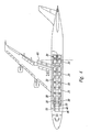
- Figures 3-5 show another embodiment of the aerial fluid delivery system 1 in conjunction with a large aircraft such as a Boeing 747 (shown in the drawings), DC 10, Airbus 380, or other substantially large aircraft.
- a large aircraft such as a Boeing 747 (shown in the drawings), DC 10, Airbus 380, or other substantially large aircraft.
- the pressure vessel tanks 46 are positioned transverse to the longitudinal dimension of the fuselage 3.
- a greater number of material storage tanks 30 are also used and are distributed in port and starboard pairs along the longitudinal direction of the fuselage 3 to better distribute load within the aircraft.
- the material storage tanks 30 are sized in the depicted embodiment such that the forward most pair of tanks (1 L and 1 R in Figure 4 ) are smallest, the second forward pair of tanks (2L and 2R in Figure 4 ) are larger, the next two pairs of tanks (3L, 3R and 4L, 4R in Figure 4 ) are largest and the aft most pair of tanks (5L and 5R in Figure 4 ) are sized similar to the second forward pair of tanks (2L and 2R in Figure 4 ).
- the implementation as depicted in Figures 3-5 has the air lines 55 connected to the most forward pair of tanks (1 L and 1 R in Figure 4 ) so that the most forward pair of tanks empties first, then the second forward pair of tanks empties.
- the center of gravity of the aircraft when the material storage tanks 30 are full is near the forward most center of gravity limit point CGf and is near the aft most center of gravity limit point CGa when the material storage tanks are substantially empty.
- lines for the dump manifold 70 protrude in a direction perpendicular to the longitudinal dimension of the aircraft from the aft most pair (5L and 5R in Figure 4 ) of material storage tanks 30, which allows the aft most pair of material storage tanks to be located farther aft in the aircraft relative to the outlets 5 than the first embodiment.
- outlets 5 are again directed to emit in a downward direction approximately perpendicular to the longitudinal dimension of the fuselage 3.
- This downward perpendicular direction of emission combined with the pressurized nature of emission is designed to project the contents of the material storage tanks 30 not only past the aircraft and substantially past the aircraft turbulence to a great degree, but also so the contents can be better directed downward toward objects or other targets generally located on that portion of the earth in a vicinity below the aircraft.
- the outlets 5 are generally located along the longitudinal dimension of the aircraft relatively near the trailing edge (the most aft edge) of the inboard flaps 90 in their extended position.
- the extended position of the inboard flaps 90 is taken into consideration since the aircraft is generally travelling at reduced speed with the inboard flaps in an extended position at the time of dumping of the content of the material storage tanks 30. It has been found that in this area just aft of the trailing edge of the extended inboard flaps 90 that there is a minimal amount of turbulence to be dealt with. If the outlets 5 are moved forward of the trailing edge of the inboard flaps 90 or moved more aft toward the tail of the aircraft, there can be more turbulence, which can reduce ability to delivery content of the material storage tanks 30 to the ground generally below the aircraft in sufficient concentrations.
- the outlets 5 are sized with relatively large pipe diameters such as having 16 inch diameters in some implementations. With large pipe diameters for the outlets 5 and substantially high pressure levels for the pressure vessel tanks 46, such as 65 psi, a substantial amount of thrust induced force can result from the material in the material storage tanks 30 being shot out from the large diameter outlets at high pressure.
- Conventional methods of securing outlets to an aircraft involve common techniques to secure pallets to the aircraft, such as with outer guide locks.
- An outlet securing system 100 is depicted in Figure 6 to properly distribute the unconventionally high thrust induced loads to an adequately sized portion of the aircraft.
- the outlet securing system 100 couples the outlets 5 to the aircraft by coupling to seat tracks 101 originally designed for securing passenger seats to the aircraft when the aircraft is used as a passenger airliner. Coupling the outlets 5 to the aircraft by coupling the outlets to the seat tracks 101 allows for a more secure way of imparting the thrust induced load to the aircraft structure than the conventional methods used involving securing pallets to the aircraft. Consequently, the outlet securing system 100 allows the aerial delivery system 1 to delivery greater quantities of material with air tank pressures substantially higher than used by conventional delivery systems.
- the outlet securing system 100 includes brace beams 102 coupled to the outlets 5 with conforming spacers 104 and bolts 106.
- the brace beams 102 are coupled to frame members 108 with bolts 110.
- the frame members 108 are in turn coupled to seat track spanning members 112 with bolts 114.
- the seat track spanning members 112 can be sized to span between two or more of the seat tracks 101.
- the seat track spanning members 112 are coupled to seat track couplers 116 with bolts 118.
- the seat track couplers 116 are shaped and fashioned to directly fasten to portions of a plurality of the seat tracks 101 (shown in Figure 6 as coupling to portions of four of the seat tracks of the aircraft).
- Figure 6 has depicted a particular structure for the outlet securing system 100, other implementations are also envisioned that involve other configurations of frame members and seat track couplers while retaining a general approach of securing the outlets 5 to portions of one or more of the seat tracks 101 found in the aircraft for enhanced load distribution.
- the aerial fluid delivery system is capable of association with an aircraft comprising: an aboard area and an outer area of the aircraft; an air accumulator associated with a plurality of tanks, the air accumulator located in the aboard area of the aircraft, the tanks capable of containing a fluid, the air accumulator capable of propelling the fluid contained in the tanks; a dump manifold associated with the tanks; and a dump valve, the dump valve associated with the dump manifold, wherein the fluid is directed by pressure in the accumulator and is propelled through the dump valve downward from the aboard area of the aircraft.
- the aerial fluid delivery system may have the fluid selected from the group consisting of at least a water, gel, decontamination compound, weather modification compound, oil spill treatment compound, and a firefighting compound.
- the aerial fluid delivery system may be capable of association with an airplane, helicopter, or balloon.
- the aerial fluid delivery system 1 is used with an aircraft having a wing box comprising: an air accumulator, the air accumulator capable of holding high-pressure air; a high pressure line; at least a material holding tank connected to the air accumulator by the high pressure line, the material holding tank having a forward end and an aft end; a high pressure regulator associated with the air accumulator, wherein the high pressure regulator allows the air accumulator to hold large amounts of air at high pressures so low and constant air pressure can be delivered to the material holding tank; at least a separation valve associated with the aft end of the material holding tank; a dump manifold associated with the material holding tank; and a dump outlet associated with the dump manifold, the dump outlets located behind the aircraft wing box, wherein the fluid held within the material holding tank is capable of exiting the system from the dump outlets under propulsion from high pressure air from the air accumulator.
- the aerial fluid delivery system may include a faring housed over the dump outlet.
- the aerial fluid delivery system may use a pressure vessel tank as the air accumulator.
- the aerial fluid delivery system may use the a high pressure vessel as the material holding tank.
- the aerial fluid delivery system may further include a second material holding tank, the material holding tank and the second material holding tank being joined to form a branching T joint.
- the material holding tank, and the second material holding tank may be joined to form a branching Y joint.
- the aerial fluid delivery system may use a material holding tank made of steel.
- the aerial fluid delivery system may use a butterfly valve as a separation valve.
- the separation valve may be located on each side of the branching T joint, or be located on each side of the branching Y joint, depending on which is used.
- the aerial fluid delivery system may use a chute as the dump outlet.
- the dump outlet may be a nozzle.
- the aerial fluid delivery system may further include a drop controller.
- the aerial fluid delivery system may include a second material holding tank, with the material holding tank and the second material holding tank located generally longitudinal with the aircraft.
- the aerial fluid delivery system may use a Boeing 747 aircraft.
- the present invention further relates to:
Landscapes
- Life Sciences & Earth Sciences (AREA)
- Biodiversity & Conservation Biology (AREA)
- Ecology (AREA)
- Forests & Forestry (AREA)
- Health & Medical Sciences (AREA)
- Public Health (AREA)
- Business, Economics & Management (AREA)
- Emergency Management (AREA)
- Engineering & Computer Science (AREA)
- Aviation & Aerospace Engineering (AREA)
- Filling Or Discharging Of Gas Storage Vessels (AREA)
- Catching Or Destruction (AREA)
- Fire-Extinguishing By Fire Departments, And Fire-Extinguishing Equipment And Control Thereof (AREA)
Applications Claiming Priority (3)
| Application Number | Priority Date | Filing Date | Title |
|---|---|---|---|
| US47782903P | 2003-06-11 | 2003-06-11 | |
| US57181904P | 2004-05-17 | 2004-05-17 | |
| EP20040776537 EP1644246B1 (fr) | 2003-06-11 | 2004-06-14 | Methode de Largage Aerien de Matériau |
Related Parent Applications (1)
| Application Number | Title | Priority Date | Filing Date |
|---|---|---|---|
| EP04776537.5 Division | 2004-06-14 |
Publications (2)
| Publication Number | Publication Date |
|---|---|
| EP2228302A2 true EP2228302A2 (fr) | 2010-09-15 |
| EP2228302A3 EP2228302A3 (fr) | 2010-11-17 |
Family
ID=33514162
Family Applications (2)
| Application Number | Title | Priority Date | Filing Date |
|---|---|---|---|
| EP20100006765 Withdrawn EP2228302A3 (fr) | 2003-06-11 | 2004-06-14 | Système de distribution aérienne |
| EP20040776537 Expired - Lifetime EP1644246B1 (fr) | 2003-06-11 | 2004-06-14 | Methode de Largage Aerien de Matériau |
Family Applications After (1)
| Application Number | Title | Priority Date | Filing Date |
|---|---|---|---|
| EP20040776537 Expired - Lifetime EP1644246B1 (fr) | 2003-06-11 | 2004-06-14 | Methode de Largage Aerien de Matériau |
Country Status (6)
| Country | Link |
|---|---|
| US (2) | US7413145B2 (fr) |
| EP (2) | EP2228302A3 (fr) |
| AT (1) | ATE519673T1 (fr) |
| AU (2) | AU2004245570B2 (fr) |
| CA (2) | CA2529060C (fr) |
| WO (1) | WO2004108528A2 (fr) |
Cited By (3)
| Publication number | Priority date | Publication date | Assignee | Title |
|---|---|---|---|---|
| RU2486593C2 (ru) * | 2009-12-16 | 2013-06-27 | Закрытое акционерное общество "Научно-технический центр "КАЧЕСТВО" | Авиационное аэрозольное устройство и способ маркирования места происшествия |
| CN112607031A (zh) * | 2020-12-22 | 2021-04-06 | 西安羚控电子科技有限公司 | 一种模块化无人机集群空中快速投放系统 |
| FR3148576A1 (fr) * | 2023-07-27 | 2024-11-15 | Airbus Operations | Aéronef comportant au moins un réservoir tubulaire de stockage d’un fluide extincteur |
Families Citing this family (46)
| Publication number | Priority date | Publication date | Assignee | Title |
|---|---|---|---|---|
| ATE519673T1 (de) * | 2003-06-11 | 2011-08-15 | Evergreen Internat Aviat Inc | Methode für materialausbringung aus der luft |
| US7624666B1 (en) * | 2003-07-08 | 2009-12-01 | Raytheon Company | Obscuration method for reducing the infrared signature of an object |
| US7284727B2 (en) * | 2003-10-01 | 2007-10-23 | L-3 Integrated Systems Company | Systems and methods for aerial dispersion of materials |
| US6889940B1 (en) * | 2004-01-29 | 2005-05-10 | The Boeing Company | Auxiliary fuel tank systems for aircraft and methods for their manufacture and use |
| US7051979B2 (en) * | 2004-01-29 | 2006-05-30 | The Boeing Company | Auxiliary fuel tank systems for aircraft and methods for their manufacture and use |
| US7357149B2 (en) * | 2004-01-29 | 2008-04-15 | The Boeing Company | Auxiliary fuel tank systems for aircraft and methods for their manufacture and use |
| US7198226B2 (en) * | 2004-06-03 | 2007-04-03 | The Boeing Company | Landing assist apparatus retention strap spool |
| US7344108B2 (en) * | 2004-06-03 | 2008-03-18 | The Boeing Company | Landing assist apparatus interface bulkhead and method of installation |
| US7303168B1 (en) * | 2005-02-25 | 2007-12-04 | Lazes Richard J | Aircraft spraying conversion kit for use in extinguishing fires |
| US7735781B1 (en) * | 2005-07-18 | 2010-06-15 | United States Of America As Represented By The Secretary Of The Navy | Method and system for deployment of ordnance from an aircraft in mid-flight |
| US7819362B2 (en) * | 2007-03-01 | 2010-10-26 | Evergreen International Aviation, Inc. | Enhanced aerial delivery system |
| DE102008019146A1 (de) * | 2008-04-16 | 2009-11-05 | Airbus Deutschland Gmbh | Enteisungssystem für ein Flugzeug |
| US8165731B2 (en) * | 2008-09-12 | 2012-04-24 | Lonestar Inventions, L.P. | System for aerial delivery of fire retardant |
| US9945753B2 (en) * | 2009-01-13 | 2018-04-17 | United Aeronautical Corp. | Cargo loading trailer |
| US9192797B2 (en) * | 2010-02-19 | 2015-11-24 | Leonard E. Doten | Fire suppression gel blender and airborne delivery system |
| RU2476354C2 (ru) * | 2011-11-29 | 2013-02-27 | Виктор Александрович Кравченко | Вертосамолет-п (пожарный) |
| ITMI20120593A1 (it) * | 2012-04-12 | 2013-10-13 | Marco Ghio | Procedimento e dispositivo di controllo per incendi |
| EP2879012A1 (fr) * | 2013-11-29 | 2015-06-03 | The Boeing Company | Système et procédé pour commander une charge utile d'un aéronef |
| US9555886B1 (en) | 2014-04-22 | 2017-01-31 | Oubada Hawass | Multi-modular aerial firefighting control method and apparatus |
| US10195471B2 (en) * | 2014-08-01 | 2019-02-05 | Leonard E. Doten | Aircraft firefighting tank with mixing |
| US9656108B2 (en) * | 2014-08-01 | 2017-05-23 | Leonard E. Doten | Aircraft water tank polymer gel preparation system |
| US9266609B1 (en) * | 2014-10-20 | 2016-02-23 | Insitu, Inc | Dual mode flight vehicle |
| US8967029B1 (en) | 2014-11-20 | 2015-03-03 | TMARS Associates, Trustee for Toxic mosquito aerial release system CRT Trust | Toxic mosquito aerial release system |
| US10370110B2 (en) * | 2016-09-21 | 2019-08-06 | General Electric Company | Aircraft having an aft engine |
| US10273003B2 (en) * | 2017-04-14 | 2019-04-30 | Britton COULSON | Multi-tank system for aerial firefighting aircraft |
| US11836807B2 (en) | 2017-12-02 | 2023-12-05 | Mighty Fire Breaker Llc | System, network and methods for estimating and recording quantities of carbon securely stored in class-A fire-protected wood-framed and mass-timber buildings on construction job-sites, and class-A fire-protected wood-framed and mass timber components in factory environments |
| US11865394B2 (en) | 2017-12-03 | 2024-01-09 | Mighty Fire Breaker Llc | Environmentally-clean biodegradable water-based concentrates for producing fire inhibiting and fire extinguishing liquids for fighting class A and class B fires |
| US12594448B2 (en) | 2019-06-22 | 2026-04-07 | Mighty Fire Breaker Llc | Environmentally-clean aqueous-based fire extinguishing biochemical liquid concentrates for mixing with proportioned quantities of water to produce fire extinguishing water streams |
| US10653904B2 (en) | 2017-12-02 | 2020-05-19 | M-Fire Holdings, Llc | Methods of suppressing wild fires raging across regions of land in the direction of prevailing winds by forming anti-fire (AF) chemical fire-breaking systems using environmentally clean anti-fire (AF) liquid spray applied using GPS-tracking techniques |
| US11395931B2 (en) | 2017-12-02 | 2022-07-26 | Mighty Fire Breaker Llc | Method of and system network for managing the application of fire and smoke inhibiting compositions on ground surfaces before the incidence of wild-fires, and also thereafter, upon smoldering ambers and ashes to reduce smoke and suppress fire re-ignition |
| US10260232B1 (en) | 2017-12-02 | 2019-04-16 | M-Fire Supression, Inc. | Methods of designing and constructing Class-A fire-protected multi-story wood-framed buildings |
| US11865390B2 (en) | 2017-12-03 | 2024-01-09 | Mighty Fire Breaker Llc | Environmentally-clean water-based fire inhibiting biochemical compositions, and methods of and apparatus for applying the same to protect property against wildfire |
| US10311444B1 (en) | 2017-12-02 | 2019-06-04 | M-Fire Suppression, Inc. | Method of providing class-A fire-protection to wood-framed buildings using on-site spraying of clean fire inhibiting chemical liquid on exposed interior wood surfaces of the wood-framed buildings, and mobile computing systems for uploading fire-protection certifications and status information to a central database and remote access thereof by firefighters on job site locations during fire outbreaks on construction sites |
| US20240157180A1 (en) | 2021-02-04 | 2024-05-16 | Mighty Fire Breaker Llc | Method of and kit for installing and operating a wildfire defense spraying system on a property parcel for proactively spraying environmentally-clean liquid fire inhibitor thereover to inhibit fire ignition and flame spread caused by wind-driven wildfire embers |
| US10290004B1 (en) | 2017-12-02 | 2019-05-14 | M-Fire Suppression, Inc. | Supply chain management system for supplying clean fire inhibiting chemical (CFIC) totes to a network of wood-treating lumber and prefabrication panel factories and wood-framed building construction job sites |
| US10695597B2 (en) | 2017-12-02 | 2020-06-30 | M-Fire Holdings Llc | Method of and apparatus for applying fire and smoke inhibiting compositions on ground surfaces before the incidence of wild-fires, and also thereafter, upon smoldering ambers and ashes to reduce smoke and suppress fire re-ignition |
| US10814150B2 (en) | 2017-12-02 | 2020-10-27 | M-Fire Holdings Llc | Methods of and system networks for wireless management of GPS-tracked spraying systems deployed to spray property and ground surfaces with environmentally-clean wildfire inhibitor to protect and defend against wildfires |
| US10332222B1 (en) | 2017-12-02 | 2019-06-25 | M-Fire Supression, Inc. | Just-in-time factory methods, system and network for prefabricating class-A fire-protected wood-framed buildings and components used to construct the same |
| US10430757B2 (en) | 2017-12-02 | 2019-10-01 | N-Fire Suppression, Inc. | Mass timber building factory system for producing prefabricated class-A fire-protected mass timber building components for use in constructing prefabricated class-A fire-protected mass timber buildings |
| US11826592B2 (en) | 2018-01-09 | 2023-11-28 | Mighty Fire Breaker Llc | Process of forming strategic chemical-type wildfire breaks on ground surfaces to proactively prevent fire ignition and flame spread, and reduce the production of smoke in the presence of a wild fire |
| US11911643B2 (en) | 2021-02-04 | 2024-02-27 | Mighty Fire Breaker Llc | Environmentally-clean fire inhibiting and extinguishing compositions and products for sorbing flammable liquids while inhibiting ignition and extinguishing fire |
| US20240252866A1 (en) | 2020-03-01 | 2024-08-01 | Mighty Fire Breaker Llc | Liquid hydrocarbon sorbing article of manufacture for inhibiting fire ignition involving flammable liquid hydrocarbons, while absorbing the flammable liquid hydrocarbons when spilled on a body of water and/or land |
| CA3209766A1 (fr) * | 2022-08-30 | 2024-02-29 | Airbus (S.A.S.) | Dispositif de largage de fluide dans une direction determinee pour aeronef hote de lutte contre le feu et aeronef equipe d'un tel dispositif |
| US20240066337A1 (en) * | 2022-08-30 | 2024-02-29 | Airbus Sas | Device for controlling, as a function of at least one parametrized criterion, a system for jettisoning fluid for a firefighting host aircraft |
| US12365460B1 (en) | 2024-10-31 | 2025-07-22 | Charles Hamilton Barfield, III | Aerial spreading device |
| CN119408710B (zh) * | 2024-11-11 | 2026-02-10 | 中国商用飞机有限责任公司 | 飞行器投放装置和包含该飞行器投放装置的飞行器 |
Family Cites Families (27)
| Publication number | Priority date | Publication date | Assignee | Title |
|---|---|---|---|---|
| US242677A (en) | 1881-06-07 | Gravity grain-separator | ||
| US1911431A (en) * | 1931-05-14 | 1933-05-30 | Aloysius J Cawley | Irrigation apparatus |
| US1997669A (en) * | 1934-02-23 | 1935-04-16 | Arcieri Antonio | Aeroplane attachment for extinguishing fires |
| US2242705A (en) * | 1939-02-06 | 1941-05-20 | Gordon Isaac | Water spraying airplane |
| US2412729A (en) | 1941-09-09 | 1946-12-17 | Cons Vultee Aircraft Corp | Aircraft load handling system |
| GB564771A (en) | 1943-04-08 | 1944-10-12 | Walter Eugene Ripper | Improved means for aerial spraying |
| US2426771A (en) * | 1944-10-09 | 1947-09-02 | Charles B Harp | Airplane mounted fire extinguishing apparatus |
| US2493017A (en) * | 1946-08-05 | 1950-01-03 | Ervin J Nutter | Grid spray nozzle |
| US2926688A (en) * | 1956-05-08 | 1960-03-01 | Beech Aircraft Corp | Precise control distribution of airplane fuel stores |
| DE977805C (de) * | 1967-02-27 | 1970-07-30 | Messerschmitt Boelkow Blohm | Einrichtung zum Abwerfen von Schuettgut aus an Flugzeugen befestigten Behaeltern |
| US3698480A (en) * | 1971-07-12 | 1972-10-17 | Aero Union Corp | Dual tank air borne fire retardant dispensing system |
| US3828857A (en) | 1971-12-07 | 1974-08-13 | A Mason | Apparatus for filling and emptying containers for use in firefighting |
| US3995328A (en) * | 1974-12-13 | 1976-12-07 | The Boeing Company | Vacuum toilet system |
| US4172499A (en) * | 1977-12-05 | 1979-10-30 | Canadair Limited | Powder and water mixing and dropping system onboard an aircraft |
| US4208949A (en) * | 1978-05-03 | 1980-06-24 | Boeing Commercial Airplane Company | Missile carrier airplane |
| US4202061A (en) * | 1978-12-29 | 1980-05-13 | The Boeing Company | Lavatory wastewater disposal system for aircraft |
| GB8421988D0 (en) | 1984-08-31 | 1984-10-24 | Ndn Aircraft Ltd | Aircraft |
| DE4202719C2 (de) * | 1992-01-31 | 1993-11-04 | Deutsche Aerospace Airbus | Wassersystem fuer ein flugzeug |
| CA2070546A1 (fr) * | 1992-06-05 | 1993-12-06 | Larry T. Pahl | Systeme de distribution aerien a regulation de debit |
| US5385208A (en) * | 1993-04-13 | 1995-01-31 | Baker; R. Arnold | Airborne fire suppressant foam delivery apparatus |
| DE4408493C1 (de) * | 1994-03-14 | 1995-02-09 | Deutsche Aerospace Airbus | Vorrichtung zur Abwasserdrainage aus Flugzeugen |
| DE19609939C1 (de) * | 1996-03-14 | 1997-09-11 | Daimler Benz Aerospace Airbus | Wassersystem in Flugzeugen |
| US6626375B1 (en) * | 2000-10-19 | 2003-09-30 | Cybercore, Inc. | Method and apparatus for aerial spray marking of ground surfaces |
| US20020121382A1 (en) * | 2001-03-02 | 2002-09-05 | Fima Raoul G. | Lighter-than-air water dispensing airship for fire control |
| US6758441B2 (en) * | 2002-07-25 | 2004-07-06 | The Boeing Company | Store ejection system with replaceable pressure vessel |
| US6622966B1 (en) * | 2002-09-23 | 2003-09-23 | Mcconnell, Sr. John R. | System for extinguishing wild fires and method therefor |
| ATE519673T1 (de) | 2003-06-11 | 2011-08-15 | Evergreen Internat Aviat Inc | Methode für materialausbringung aus der luft |
-
2004
- 2004-06-14 AT AT04776537T patent/ATE519673T1/de not_active IP Right Cessation
- 2004-06-14 AU AU2004245570A patent/AU2004245570B2/en not_active Ceased
- 2004-06-14 EP EP20100006765 patent/EP2228302A3/fr not_active Withdrawn
- 2004-06-14 CA CA 2529060 patent/CA2529060C/fr not_active Expired - Fee Related
- 2004-06-14 EP EP20040776537 patent/EP1644246B1/fr not_active Expired - Lifetime
- 2004-06-14 CA CA 2689610 patent/CA2689610A1/fr not_active Abandoned
- 2004-06-14 US US10/867,571 patent/US7413145B2/en not_active Expired - Lifetime
- 2004-06-14 WO PCT/US2004/018846 patent/WO2004108528A2/fr not_active Ceased
-
2008
- 2008-07-30 US US12/182,505 patent/US7748662B2/en not_active Expired - Fee Related
-
2010
- 2010-01-14 AU AU2010200149A patent/AU2010200149A1/en not_active Abandoned
Non-Patent Citations (1)
| Title |
|---|
| None |
Cited By (5)
| Publication number | Priority date | Publication date | Assignee | Title |
|---|---|---|---|---|
| RU2486593C2 (ru) * | 2009-12-16 | 2013-06-27 | Закрытое акционерное общество "Научно-технический центр "КАЧЕСТВО" | Авиационное аэрозольное устройство и способ маркирования места происшествия |
| CN112607031A (zh) * | 2020-12-22 | 2021-04-06 | 西安羚控电子科技有限公司 | 一种模块化无人机集群空中快速投放系统 |
| CN112607031B (zh) * | 2020-12-22 | 2022-02-22 | 西安羚控电子科技有限公司 | 一种模块化无人机集群空中快速投放系统 |
| FR3148576A1 (fr) * | 2023-07-27 | 2024-11-15 | Airbus Operations | Aéronef comportant au moins un réservoir tubulaire de stockage d’un fluide extincteur |
| EP4497680A1 (fr) * | 2023-07-27 | 2025-01-29 | Airbus Operations (S.A.S.) | Aéronef comportant au moins un réservoir tubulaire de stockage d'un fluide extincteur |
Also Published As
| Publication number | Publication date |
|---|---|
| US20050017131A1 (en) | 2005-01-27 |
| AU2010200149A1 (en) | 2010-02-04 |
| US7748662B2 (en) | 2010-07-06 |
| ATE519673T1 (de) | 2011-08-15 |
| EP1644246B1 (fr) | 2011-08-10 |
| AU2004245570A1 (en) | 2004-12-16 |
| EP2228302A3 (fr) | 2010-11-17 |
| EP1644246A2 (fr) | 2006-04-12 |
| EP1644246A4 (fr) | 2009-04-22 |
| AU2004245570B2 (en) | 2010-04-08 |
| WO2004108528A2 (fr) | 2004-12-16 |
| CA2529060C (fr) | 2010-11-02 |
| WO2004108528A3 (fr) | 2005-06-09 |
| CA2529060A1 (fr) | 2004-12-16 |
| US7413145B2 (en) | 2008-08-19 |
| CA2689610A1 (fr) | 2004-12-16 |
| US20090065646A1 (en) | 2009-03-12 |
Similar Documents
| Publication | Publication Date | Title |
|---|---|---|
| US7413145B2 (en) | Aerial delivery system | |
| CA2879287C (fr) | Systeme de distribution aerienne ameliore | |
| US4979571A (en) | Foam producing apparatus and method for emergency foam delivery systems | |
| JP6116557B2 (ja) | 拡張可能な貨物消火剤分配システム | |
| US9750963B2 (en) | Advanced airborne fire fighting system | |
| US7165627B2 (en) | Portable airborne firefighting and sensing system | |
| US20050183869A1 (en) | Fire-suppression system for an aircraft | |
| US11897614B2 (en) | Multi-purpose passenger aircraft, use thereof, operation method therefore and passenger aircraft series | |
| EP3374267B1 (fr) | Système de carburant pour aéronef | |
| US20070246609A1 (en) | Method for Expelling a Fluid Medium from an Aircraft | |
| US20140224935A1 (en) | Aircraft Liquid Dispensing System | |
| US20210107650A1 (en) | Aerial firefighting system | |
| ES2369832T3 (es) | Procedimiento para la liberación aérea de material. | |
| RU2339545C2 (ru) | Способ выброса текучей среды с борта летательного аппарата |
Legal Events
| Date | Code | Title | Description |
|---|---|---|---|
| PUAI | Public reference made under article 153(3) epc to a published international application that has entered the european phase |
Free format text: ORIGINAL CODE: 0009012 |
|
| AC | Divisional application: reference to earlier application |
Ref document number: 1644246 Country of ref document: EP Kind code of ref document: P |
|
| AK | Designated contracting states |
Kind code of ref document: A2 Designated state(s): AT BE BG CH CY CZ DE DK EE ES FI FR GB GR HU IE IT LI LU MC NL PL PT RO SE SI SK TR |
|
| PUAL | Search report despatched |
Free format text: ORIGINAL CODE: 0009013 |
|
| AK | Designated contracting states |
Kind code of ref document: A3 Designated state(s): AT BE BG CH CY CZ DE DK EE ES FI FR GB GR HU IE IT LI LU MC NL PL PT RO SE SI SK TR |
|
| STAA | Information on the status of an ep patent application or granted ep patent |
Free format text: STATUS: THE APPLICATION IS DEEMED TO BE WITHDRAWN |
|
| 18D | Application deemed to be withdrawn |
Effective date: 20110518 |