EP2228501B1 - Système de support de toit - Google Patents
Système de support de toit Download PDFInfo
- Publication number
- EP2228501B1 EP2228501B1 EP09155561A EP09155561A EP2228501B1 EP 2228501 B1 EP2228501 B1 EP 2228501B1 EP 09155561 A EP09155561 A EP 09155561A EP 09155561 A EP09155561 A EP 09155561A EP 2228501 B1 EP2228501 B1 EP 2228501B1
- Authority
- EP
- European Patent Office
- Prior art keywords
- support foot
- base part
- foot according
- guiding structure
- profiled section
- Prior art date
- Legal status (The legal status is an assumption and is not a legal conclusion. Google has not performed a legal analysis and makes no representation as to the accuracy of the status listed.)
- Active
Links
Images

Classifications
-
- E—FIXED CONSTRUCTIONS
- E04—BUILDING
- E04D—ROOF COVERINGS; SKY-LIGHTS; GUTTERS; ROOF-WORKING TOOLS
- E04D11/00—Roof covering, as far as not restricted to features covered by only one of groups E04D1/00 - E04D9/00; Roof covering in ways not provided for by groups E04D1/00 - E04D9/00, e.g. built-up roofs, elevated load-supporting roof coverings
- E04D11/005—Supports for elevated load-supporting roof coverings
-
- E—FIXED CONSTRUCTIONS
- E04—BUILDING
- E04D—ROOF COVERINGS; SKY-LIGHTS; GUTTERS; ROOF-WORKING TOOLS
- E04D11/00—Roof covering, as far as not restricted to features covered by only one of groups E04D1/00 - E04D9/00; Roof covering in ways not provided for by groups E04D1/00 - E04D9/00, e.g. built-up roofs, elevated load-supporting roof coverings
-
- E—FIXED CONSTRUCTIONS
- E04—BUILDING
- E04D—ROOF COVERINGS; SKY-LIGHTS; GUTTERS; ROOF-WORKING TOOLS
- E04D13/00—Special arrangements or devices in connection with roof coverings; Protection against birds; Roof drainage ; Sky-lights
- E04D13/12—Devices or arrangements allowing walking on the roof or in the gutter
-
- E—FIXED CONSTRUCTIONS
- E04—BUILDING
- E04F—FINISHING WORK ON BUILDINGS, e.g. STAIRS, FLOORS
- E04F15/00—Flooring
- E04F15/02—Flooring or floor layers composed of a number of similar elements
- E04F15/024—Sectional false floors, e.g. computer floors
-
- F—MECHANICAL ENGINEERING; LIGHTING; HEATING; WEAPONS; BLASTING
- F24—HEATING; RANGES; VENTILATING
- F24S—SOLAR HEAT COLLECTORS; SOLAR HEAT SYSTEMS
- F24S25/00—Arrangement of stationary mountings or supports for solar heat collector modules
- F24S25/10—Arrangement of stationary mountings or supports for solar heat collector modules extending in directions away from a supporting surface
-
- F—MECHANICAL ENGINEERING; LIGHTING; HEATING; WEAPONS; BLASTING
- F24—HEATING; RANGES; VENTILATING
- F24S—SOLAR HEAT COLLECTORS; SOLAR HEAT SYSTEMS
- F24S25/00—Arrangement of stationary mountings or supports for solar heat collector modules
- F24S25/10—Arrangement of stationary mountings or supports for solar heat collector modules extending in directions away from a supporting surface
- F24S25/11—Arrangement of stationary mountings or supports for solar heat collector modules extending in directions away from a supporting surface using shaped bodies, e.g. concrete elements, foamed elements or moulded box-like elements
-
- F—MECHANICAL ENGINEERING; LIGHTING; HEATING; WEAPONS; BLASTING
- F24—HEATING; RANGES; VENTILATING
- F24S—SOLAR HEAT COLLECTORS; SOLAR HEAT SYSTEMS
- F24S25/00—Arrangement of stationary mountings or supports for solar heat collector modules
- F24S25/60—Fixation means, e.g. fasteners, specially adapted for supporting solar heat collector modules
- F24S25/61—Fixation means, e.g. fasteners, specially adapted for supporting solar heat collector modules for fixing to the ground or to building structures
- F24S25/617—Elements driven into the ground, e.g. anchor-piles; Foundations for supporting elements; Connectors for connecting supporting structures to the ground or to flat horizontal surfaces
-
- Y—GENERAL TAGGING OF NEW TECHNOLOGICAL DEVELOPMENTS; GENERAL TAGGING OF CROSS-SECTIONAL TECHNOLOGIES SPANNING OVER SEVERAL SECTIONS OF THE IPC; TECHNICAL SUBJECTS COVERED BY FORMER USPC CROSS-REFERENCE ART COLLECTIONS [XRACs] AND DIGESTS
- Y02—TECHNOLOGIES OR APPLICATIONS FOR MITIGATION OR ADAPTATION AGAINST CLIMATE CHANGE
- Y02B—CLIMATE CHANGE MITIGATION TECHNOLOGIES RELATED TO BUILDINGS, e.g. HOUSING, HOUSE APPLIANCES OR RELATED END-USER APPLICATIONS
- Y02B10/00—Integration of renewable energy sources in buildings
- Y02B10/20—Solar thermal
-
- Y—GENERAL TAGGING OF NEW TECHNOLOGICAL DEVELOPMENTS; GENERAL TAGGING OF CROSS-SECTIONAL TECHNOLOGIES SPANNING OVER SEVERAL SECTIONS OF THE IPC; TECHNICAL SUBJECTS COVERED BY FORMER USPC CROSS-REFERENCE ART COLLECTIONS [XRACs] AND DIGESTS
- Y02—TECHNOLOGIES OR APPLICATIONS FOR MITIGATION OR ADAPTATION AGAINST CLIMATE CHANGE
- Y02E—REDUCTION OF GREENHOUSE GAS [GHG] EMISSIONS, RELATED TO ENERGY GENERATION, TRANSMISSION OR DISTRIBUTION
- Y02E10/00—Energy generation through renewable energy sources
- Y02E10/40—Solar thermal energy, e.g. solar towers
- Y02E10/47—Mountings or tracking
Definitions
- the present invention relates to a roof support system.
- the present invention relates to a roof support foot for a free standing structure on a roof.
- a support foot for a modular portable stage and floor system.
- the known support foot has a ground engaging plate having an upwardly facing arcuate surface.
- a slide plate is is shiftably carried along the upper surface of the ground engaging plate to allow levelling of the slide plate relative to the ground engaging plate.
- FIG. 1 659 314 Another support foot is known from DE 1 659 314 .
- This known support foot is adapted to support plate-like construction elements.
- the foot comprises a bracket with an arcuate portion, which bracket can be fixed to a roof.
- the arcuate portion is provided with an elongate hole through which a support bolt extends.
- the upper end of the support bolt is provided with a support arm for carrying the plate-like construction elements.
- the upper and lower surface of the arcuate portion of the bracket are engaged by arcuate washers.
- the bolt can be fixed to the bracket in a certain orientation by means of nuts threaded on the bolt and engaging the washers.
- the present invention has for an object to provide an improved support system for free standing structures on a flat roof.
- the base part With the support foot according to the invention, which is placed on a flat roof with an inclination, the base part essentially has an inclined position due to the slope of the flat roof.
- the position of the skid part on the guiding structure of the base part can be adjusted such that the profiled section can be positioned in a vertical or horizontal direction, notwithstanding the fact that the base part is resting on an inclined roof surface.
- a support foot is provided which can be used on many different flat roofs and which can be adjusted easily on site to the circumstances.
- the guiding structure comprises an arched path such that the profiled section received in the skid part can be positioned in different inclinations, by positioning the skid part on different positions on the arched path.
- the guiding structure has a first arched sliding surface
- the skid part has a second arched sliding surface which is complementary to the first arched sliding surface and engages said first arched sliding surface, wherein preferably the first arched sliding surface is convex and the second arched sliding surface is concave.
- the arched path on the base part is flanked by two side walls for preventing movement of the skid part in a direction transverse to the arched path. In this way a simple sideways support for the skid part is provided, which provides additional guiding of the skid part on the arched path.
- the securing means for securing the skid part in said desired angular position on the base part comprise tensioning means for clamping the skid part to the guiding structure of the base part.
- the skid part has at least one bore and the guiding structure has a slotted hole
- the securing means comprising at least one male tensioning member, preferably a bolt, which extends through said bore and through said slotted hole, the slotted hole allowing the skid part with the male tensioning member to be positioned in the desired position on the guiding structure
- the securing means furthermore comprising a female tensioning member, preferably including a nut, for cooperating with the male tensioning member so as to secure the skid part in said desired position on the base part.
- the guiding structure on the side opposite the side where the skid part engages, at least at the location of the slotted hole has a counter surface on which the female tensioning member engages.
- the counter surface is provided with ribs, which provides an even better grip of the female tensioning member on the base part.
- the female tensioning member may comprise a clamping member which engages the counter surface, as well as a nut for tensioning the clamping member against the counter surface, wherein preferably the clamping member has a cavity in which the nut is accommodated.
- the clamping member has ribs which engage the ribs on the counter surface whereby a secure connection of the skid part on the base part is ensured.
- the insert element may be rotatable to discrete orientations or the insert element may be rotatable in any orientation.
- an upstanding profiled section may be oriented in any direction such that a structure placed on the roof can extend in any direction on the roof, independently from the direction of the slope.
- the base part is provided with male or female positioning means for positioning ballast elements on the base part, which ballast elements are provided with complementary male and/or female positioning means.
- ballast elements are provided with complementary male and/or female positioning means.
- one or more ballast blocks may be placed in a well defined and solid manner on top of the base part.
- the support foot may include an anti-slip and/ or anti-vibration mat which is positioned on the underside of the base part.
- the base part may be provided with male and/or female positioning means and the anti-slip and/or anti-vibration mat may be provided with female and or male positioning means engaging the male and/or female positioning means of the base part.
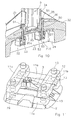
- a support foot 1 comprising a base part 2 and a skid part 3. Both parts 2, 3 are preferably made of plastic by injection moulding, but one or both parts 2, 3 may also be made of another material for example steel or another metal.
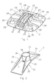
- the base part 2 is shown separately in Fig. 1 and comprises a base plate 21, which in the shown example is substantially square with rounded corners, but which may have any other suitable shape, such as circular, triangular, polygonal, etc.
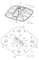
- the base plate 21 has a top side, which is visible in Fig. 1 , and a bottom side opposite thereof, which is visible in Fig. 3b .
- a guiding structure 22 including longitudinal webs 23 and transverse webs 24.
- the longitudinal webs 23 have a curved upper edge.
- the web arrangement is flanked by two side walls 26.
- the side walls 26 extend in an upward direction beyond the upper edges of the webs 23, 24.
- the side walls 26 have in the specific embodiment shown a curved upper edge, but this is not necessary.
- an arched surface portion 25 is provided in the middle region of the guiding structure 22 .
- the upper edges of the webs 23, 24 and the arched surface portion 25 constitute an arched sliding surface.
- a longitudinal slot 27 On the bottom side of the arched surface portion 25 is provided a cavity 210 which is open on the bottom side and which is visible in Fig. 3b .
- stiffening ribs 28 From the side walls 26 are extending stiffening ribs 28 on the upper side of the base plate 21 towards the edge of the base plate 21. Instead of the stiffening ribs 28, also other means for stiffening the structure my be provided.
- the positioning means 29 are hollow and open on the bottom side of the base plate 21 as can be seen in Fig. 3b .
- a skid part 3 essentially comprises an arched body 31 with a concave bottom surface 32 and a convex upper surface 33.
- the concave bottom surface 32 constitutes a sliding surface which engages the arched sliding surface of the base part 2 as can be seen in Fig. 3a .
- a cylindrical socket 34 which in the shown embodiment is integral with the arched body 31. From the outside of the socket 34 on the upper surface 31 are extending stiffening ribs 35 towards the edge of the arched body 31. It is also conceivable to have no stiffening means or other stiffening means than the ribs 35 shown in the figure.
- the socket is cylindrical with a circular cross-section, but may also have another shape.
- a socket with a square cross-section is conceivable.
- a polygonal shape is conceivable.
- a bore 36 In front of the cylindrical socket 34 on the longitudinal axis is provided a bore 36. A same bore 36 is provided on the diametrical opposite side of the socket 34.
- Fig. 3a is shown that the skid part 3 is mounted on the guiding structure 22 of the base part 2.
- a vibration isolating anti-slip mat 8 On the underside of the base part 2 may be provided a vibration isolating anti-slip mat 8, which is shown separately in Fig. 8 .
- the anti-slip mat 8 is made of a suitable isolating material, for example rubber.
- the mat 8 has substantially the same contour as the base plate 21 of the base part 2 and may be ribbed on the upper side as is shown in Fig. 8 .
- the mat may also have another shape as is shown here.
- In the corner regions are provided upwardly extending male positioning means 81, which mate with the female positioning means 29 on the bottom side of the base plate 21 of the base part 2.
- Fig. 3a the skid part 3 is mounted in a middle position on the guiding structure 22.
- the centre axis of the socket 34 of the skid part 3 extends perpendicular with respect to the base plate 21 of the base part 2.
- the skid part 3 can slide on the guiding structure 22 in the direction illustrated by the double arrow indicated with reference numeral 39.
- the insert element 9 in the shown embodiment has a body 91 with a substantially square cross section, wherein the body 91 has four slotted side walls 92.
- the outer dimensions of the body 91 are such that the body 91 can be positioned in any orientation within the cylindrical socket 34.
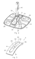
- the insert element 9 has an open upper end 93 through which a profiled section, for example a C-profile or strut profile 40 can be inserted as is shown in Fig. 4 .
- a profiled section for example a C-profile or strut profile 40 can be inserted as is shown in Fig. 4 .
- the bore of the socket 34 for inserting an insert element in may also have a square or polygonal shape instead of a circular cross section shown in Fig. 2 .
- Fig. 3a is shown how the insert element 9 is oriented such that the side walls 92 extend substantially parallel to the sliding direction 39 (see Fig. 3a ) of the skid part 3 on the guiding structure 22.
- insert element 9 can be rotated through 360° in a pre-mounting state when no profiled section is inserted.
- An arbitrary orientation of the insert element 9, different from the one in Fig. 3A is shown in Fig. 4 .
- the profiled section with the insert element can be positioned in four different angular positions
- a certain inclination of the socket 34 with respect to the base plate 21 can be selected. This is done to compensate for the slope of the flat roof on which the support foot is placed, such that the profiled section 40 extends in the vertical direction.
- the skid part 3 can be secured to the guide structure 22 of the base part 2 as is illustrated in Fig. 10 .
- a bolt (resp. male tensionning member) 50 extends through each of the bores 36 in the skid part 3.
- Each bolt 50 has a bolt head 51 which rests on the upper surface of the skid part 3.
- the bolts 50 extend through the slot 27.
- a clamping element 52 is provided with a nut 53 incorporated in it.
- the upper side of the clamping element (resp. member) 52 engages the bottom side of the arched surface portion 25, which bottom side constitutes a counter surface for the clamping action securing the skid part 3 to the base part 2.
- the counter surface is indicated by reference numeral 25a and is in the shown embodiment provided with ribs.
- the upper side of the clamping element 52 is also provided with ribs, such that upon tightening the nut 53 on the bolt 50, the clamping element 52 firmly engages the counter surface 25a and a good securement is assured.
- the clamping element 52 has a width that corresponds essentially to the width of the cavity 210.
- the clamping element 52 with the nut 53 in it can not rotate with respect to the base part 2.
- the clamping element 52 can be tensioned against the counter surface 25a by simply rotating the bolt 50 at the bolt head 51.
- the skid part can be secured on the guiding structure 22 of the base part 2 between the extreme positions on the arched surface, which might be a 7° angle with respect to the middle position.
- the maximum angle might however also be smaller or greater.
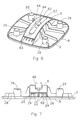
- Fig. 6 is shown a different embodiment of a support foot which is not according to the invention.
- the same base part 2 is used as is used in the previously described embodiment, thus the base part that is shown in Fig. 1 .
- the support foot of Fig. 6 has a skid part 6 which is shown separately in Fig. 6 .
- This skid part 6 is adapted to receive a profiled section 40, in this case a strut rail which extends horizontally (see Fig. 7 ) rather than in an upstanding (vertical) fashion which was described in the previously described embodiment.
- the functionality of the skid part 6 is the same as the skid part 3, but the difference is that it has no socket but a flat support surface 62 for supporting one side of a profiled section, for example a C-profile.
- the support surface 62 is somewhat countersunk in the body 61 of the skid part 6.
- bores 63 through which a bolt can be run to fix the C-rail to the skid part 6.
- bores 64 are provided through which bolts can be which extend through the slot 27 in the guiding structure 22 of the base part, to secure the skid part 6 in a certain position similar to the previously described embodiment.
- a support foot as is shown in Fig. 4 .
- the skid part 3 has been fixed under a certain angle with respect to the middle position of the skid part 3.
- the slope of a flat roof can be compensated such that the upstanding profiled section 40 (not shown in this figure) extends in a vertical direction.
- On the base plate 21 of the base part 2 are arranged two parallel ballast blocks 11a which near the respective ends are provided with holes (resp. female positioning means) 12.
- the holes 12 are positioned over the male positioning means 29 on the base plate 21, such that the ballast blocks 11a are well held in position on the base plate.
- ballast blocks 11a On the upper side of the ballast blocks 11a are provided upwardly extending protrusions (resp. male positioning means) 13. In a transverse direction are placed two parallel ballast blocks 11b. These ballast blocks are the same as the ballast blocks 11a and the protrusions 13 of the lower ballast blocks 11a are inserted in the holes 12 of the upper ballast blocks 11b.
- four ballast blocks can be positioned in a well defined and solid manner on a support foot in order to keep it standing firmly on a roof surface, even if the roof is inclined and the structure that is supported by the support foot applies some kind of tilting moment on the foot.
- ballast blocks 11a, 11b can be stacked.
Landscapes
- Engineering & Computer Science (AREA)
- General Engineering & Computer Science (AREA)
- Architecture (AREA)
- Combustion & Propulsion (AREA)
- Mechanical Engineering (AREA)
- Life Sciences & Earth Sciences (AREA)
- Sustainable Development (AREA)
- Sustainable Energy (AREA)
- Thermal Sciences (AREA)
- Chemical & Material Sciences (AREA)
- Physics & Mathematics (AREA)
- Civil Engineering (AREA)
- Structural Engineering (AREA)
- Roof Covering Using Slabs Or Stiff Sheets (AREA)
- Floor Finish (AREA)
- Exposure Of Semiconductors, Excluding Electron Or Ion Beam Exposure (AREA)
- Buildings Adapted To Withstand Abnormal External Influences (AREA)
- Paper (AREA)
- Fittings On The Vehicle Exterior For Carrying Loads, And Devices For Holding Or Mounting Articles (AREA)
- Bridges Or Land Bridges (AREA)
- Clamps And Clips (AREA)
Claims (15)
- Pied de support pour supporter une structure à pied sur un toit plat, le pied de support (1) comprenant des moyens de support (34) pour supporter une section profilée (40) sur laquelle d'autres parties de ladite structure peuvent être montées, dans lequel le pied de support (1) comprend :une partie de base (2) avec une structure de guidage (22),une partie de patin (3) qui comprend les moyens de support (34) pour la section profilée (40) et qui est montée de manière coulissante sur la structure de guidage (22) de la partie de base (2) afin de positionner les moyens de support (34) pour la section profilée (40) dans une position angulaire souhaitée permettant de compenser une pente possible d'un toit plat, etdes moyens de fixation pour fixer la partie de patin (3) dans ladite position angulaire souhaitée sur la partie de base (2),caractérisé en ce que les moyens de support (34) comprennent au moins un manchon (34) dans lequel une extrémité de la section profilée (40) peut être insérée, de sorte que la section profilée (40) est maintenue d'une manière droite,dans lequel on prévoit un élément d'insert (9) qui est prévu dans le manchon (34) et dans lequel la partie d'extrémité de la section profilée (40) est insérée, lequel élément d'insert (9) dans un état de pré-montage dans lequel aucune extrémité de section profilée n'est insérée, peut tourner autour de son axe central sur une pluralité d'orientations à l'intérieur du manchon (34), et lequel élément d'insert (9) est maintenu en position dans un état monté dans lequel la partie d'extrémité de la section profilée (40) est insérée, par serrage.
- Pied de support selon la revendication 1, dans lequel la structure de guidage (22) comprend une trajectoire arquée de sorte que la section profilée (40) reçue dans la partie de patin (3), peut être positionnée dans différentes inclinaisons.
- Pied de support selon la revendication 2, dans lequel la structure de guidage (22) a une première surface coulissante arquée, et dans lequel la partie de patin a une deuxième surface coulissante arquée (32) qui est complémentaire de la première surface coulissante arquée et met en prise ladite première surface coulissante arquée, dans lequel, de préférence, la première surface coulissante arquée est convexe et la deuxième surface coulissante arquée (32) est concave.
- Pied de support selon la revendication 2 ou 3, dans lequel la trajectoire arquée sur la partie de base (2) est flanquée par deux parois latérales (26) pour empêcher le mouvement de la partie de patin (3) dans une direction transversale par rapport à la trajectoire arquée.
- Pied de support selon l'une quelconque des revendications 1 à 4, dans lequel la partie de base (2) comprend une plaque de base (21) avec un côté supérieur et un côté inférieur, dans lequel la structure de guidage (22) est prévue sur le côté supérieur.
- Pied de support selon l'une quelconque des revendications précédentes, dans lequel les moyens de fixation comprennent des moyens de tension pour serrer la partie de patin (3) sur la structure de guidage (22) de la partie de base (2).
- Pied de support selon l'une quelconque des revendications précédentes, dans lequel la partie de patin (3) a un alésage (36) et la structure de guidage (22) a un trou fendu (27), les moyens de fixation comprenant au moins un élément de tension mâle (50), de préférence un boulon, qui s'étend à travers ledit alésage (36) et à travers ledit trou fendu (27), le trou fendu (27) permettant à la partie de patin (3) avec l'élément de tension mâle (50) d'être positionnée dans la position souhaitée sur la structure de guidage (22), les moyens de fixation comprenant en outre un élément de tension femelle (52, 53), comprenant de préférence un écrou (53), pour coopérer avec l'élément de tension mâle (50) afin de fixer la partie de patin (3) dans la position souhaitée sur la partie de base (2).
- Pied de support selon la revendication 7, dans lequel la structure de guidage (22), du côté opposé au côté où la partie de patin (3) se met en prise, au moins à l'emplacement du trou fendu (27), a une contre-surface (25a) sur laquelle l'élément de tension femelle (52, 53) se met en prise, laquelle contre-surface (25a) est de préférence prévue avec des nervures.
- Pied de support selon la revendication 8, dans lequel l'élément de tension femelle (52, 53) comprend un élément de serrage (52) qui met en prise la contre-surface (25a), ainsi qu'un écrou (53) pour tendre l'élément de serrage (52) contre la contre-surface (25a), dans lequel l'élément de serrage (52) a de préférence une ou plusieurs des caractéristiques suivantes :une cavité dans laquelle l'écrou (53) est logé,une surface de serrage nervurée pour mettre en prise la contre-surface (25a).
- Pied de support selon l'une quelconque des revendications 1 à 9, dans lequel l'élément d'insert (9) peut tourner dans différentes orientations ou peut tourner dans n'importe quelle orientation.
- Pied de support selon l'une quelconque des revendications précédentes, dans lequel le manchon a un alésage avec une forme circulaire, polygonale ou carrée en section transversale.
- Pied de support selon l'une quelconque des revendications précédentes, dans lequel l'insert a une forme externe carrée en section transversale.
- Pied de support selon l'une quelconque des revendications précédentes, dans lequel la partie de base (2) est prévue avec les moyens de positionnement mâle ou femelle (29) pour positionner des éléments de lest (11a, 11b) sur la partie de base (2), lesquels éléments de lest (11a, 11b) sont prévus avec des moyens de positionnement mâle et/ou femelle complémentaires (12, 13).
- Pied de support selon l'une quelconque des revendications précédentes, dans lequel le pied de support comprend un mât anti-glisse et/ou anti-vibration (8) qui est positionné sur la face inférieure de la partie de base (2).
- Pied de support selon la revendication 14, dans lequel la partie de base (2) est prévue avec des moyens de positionnement mâle et/ou femelle (29) et dans lequel le mât anti-glisse et/ou anti-vibration (8) est prévu avec des moyens de positionnement femelle et/ou mâle (81) mettant en prise les moyens de positionnement mâle et/ou femelle (29) de la partie de base (2).
Priority Applications (3)
| Application Number | Priority Date | Filing Date | Title |
|---|---|---|---|
| PL11156148T PL2333190T3 (pl) | 2009-03-09 | 2009-03-19 | Dachowy system nośny |
| EP11156148A EP2333190B1 (fr) | 2009-03-09 | 2009-03-19 | Système de support de toit |
| PL09155561T PL2228501T3 (pl) | 2009-03-09 | 2009-03-19 | Dachowy system nośny |
Applications Claiming Priority (1)
| Application Number | Priority Date | Filing Date | Title |
|---|---|---|---|
| PCT/NL2009/000057 WO2010104372A1 (fr) | 2009-03-09 | 2009-03-09 | Système de support sur toit |
Related Child Applications (1)
| Application Number | Title | Priority Date | Filing Date |
|---|---|---|---|
| EP11156148.6 Division-Into | 2011-02-28 |
Publications (2)
| Publication Number | Publication Date |
|---|---|
| EP2228501A1 EP2228501A1 (fr) | 2010-09-15 |
| EP2228501B1 true EP2228501B1 (fr) | 2011-05-18 |
Family
ID=40666797
Family Applications (2)
| Application Number | Title | Priority Date | Filing Date |
|---|---|---|---|
| EP09155561A Active EP2228501B1 (fr) | 2009-03-09 | 2009-03-19 | Système de support de toit |
| EP11156148A Not-in-force EP2333190B1 (fr) | 2009-03-09 | 2009-03-19 | Système de support de toit |
Family Applications After (1)
| Application Number | Title | Priority Date | Filing Date |
|---|---|---|---|
| EP11156148A Not-in-force EP2333190B1 (fr) | 2009-03-09 | 2009-03-19 | Système de support de toit |
Country Status (8)
| Country | Link |
|---|---|
| US (1) | US9404264B2 (fr) |
| EP (2) | EP2228501B1 (fr) |
| CN (1) | CN102341553B (fr) |
| AT (1) | ATE510085T1 (fr) |
| ES (2) | ES2390857T3 (fr) |
| PL (2) | PL2228501T3 (fr) |
| RU (1) | RU2495984C2 (fr) |
| WO (1) | WO2010104372A1 (fr) |
Cited By (1)
| Publication number | Priority date | Publication date | Assignee | Title |
|---|---|---|---|---|
| DE102012209395A1 (de) | 2012-06-04 | 2013-12-05 | Hilti Aktiengesellschaft | Stützfuß zur Einleitung und Verteilung von Kräften auf einen drucksensiblen Untergrund sowie Ständersystem mit einem solchen Stützfuß |
Families Citing this family (19)
| Publication number | Priority date | Publication date | Assignee | Title |
|---|---|---|---|---|
| US9831817B2 (en) * | 2009-03-03 | 2017-11-28 | Elie Rothschild | Solar panel mounting base and system for solar panel installation |
| FR2985752B1 (fr) * | 2012-01-17 | 2014-02-14 | Dani Alu | Sabot de fixation d'un montant de garde-corps |
| US8938932B1 (en) * | 2013-12-13 | 2015-01-27 | Quality Product Llc | Rail-less roof mounting system |
| WO2015110254A1 (fr) * | 2014-01-24 | 2015-07-30 | Renusol Gmbh | Unité pied d'appui servant à stabiliser des panneaux solaires sur un toit plat |
| US20150345530A1 (en) * | 2014-05-30 | 2015-12-03 | Commercial Sewing, Inc. | Pole foot |
| US10145116B2 (en) * | 2015-12-29 | 2018-12-04 | Araystays Corporation | Apparatus and methods for secure, non-invasive and non-permanent surface attachment systems |
| CN106639184B (zh) * | 2017-02-17 | 2024-05-17 | 深圳市鹏清建筑与规划设计有限公司 | 一种结构找坡之倒置屋面水落口结构 |
| CN107246532A (zh) * | 2017-05-31 | 2017-10-13 | 安徽奥睿德科技发展有限公司 | 一种用于屋面上的抗震支架 |
| CN107503477B (zh) * | 2017-07-04 | 2019-07-26 | 安徽智汇乐享科技有限公司 | 一种涡轮固定机构 |
| RU2672293C1 (ru) * | 2017-12-28 | 2018-11-13 | Игорь Викторович Прохоров | Кровельная опора (варианты) |
| NO20210286A1 (en) * | 2018-08-10 | 2021-03-03 | Lance Nill | Anchor platform assembly with angled baseplate |
| US11598098B2 (en) * | 2019-02-04 | 2023-03-07 | Omg, Inc. | Roof mount assembly with stabilized fastener matrix |
| GB2597850B (en) * | 2019-07-19 | 2022-07-13 | Big Foot Systems Ltd | Support foot |
| GB2585877B (en) * | 2019-07-19 | 2022-02-23 | Big Foot Systems Ltd | Support foot |
| US12024892B2 (en) * | 2019-09-04 | 2024-07-02 | J. Van Walraven Holding B.V. | Support foot for a free standing structure |
| AT17993U1 (de) * | 2019-09-04 | 2023-10-15 | Walraven Holding Bv J Van | Stützsockel für eine freistehende Struktur |
| DE102020119900A1 (de) * | 2020-07-28 | 2022-02-03 | Fischerwerke Gmbh & Co. Kg | Stützfuß |
| RU2769678C1 (ru) * | 2021-07-07 | 2022-04-05 | Юрий Николаевич Мамлясов | Фальц-опора для фальцевой кровли (варианты) |
| US11695369B1 (en) * | 2022-09-16 | 2023-07-04 | Sunrun Inc. | Surface mount assemblies for a solar panel system |
Family Cites Families (21)
| Publication number | Priority date | Publication date | Assignee | Title |
|---|---|---|---|---|
| US2667317A (en) * | 1949-08-04 | 1954-01-26 | Gabriel Co | Antenna mast support |
| DE1659314C3 (de) * | 1967-12-08 | 1974-02-28 | Glischke, Reinhold, 5500 Trier | Stütze zum Auflagern von Belagplatten, insbesondere von Dachbelagplatten |
| DE2139345A1 (de) | 1971-02-20 | 1973-02-15 | Helmut Mischler | Hoehenverstellbares lager fuer terrassenplatten |
| US4570397A (en) * | 1984-02-22 | 1986-02-18 | Creske Edward J | Adjustable pedestal |
| US5165642A (en) * | 1990-02-16 | 1992-11-24 | John Rihaly | Shingle holder |
| CA2101577C (fr) * | 1992-07-31 | 2005-06-07 | Dale L. Taipale | Scene modulaire portable |
| US5377976A (en) * | 1993-02-04 | 1995-01-03 | Lifetime Products, Inc. | Portable basketball system |
| US5526010A (en) * | 1995-02-09 | 1996-06-11 | Plunk; Richard L. | Support device for portable satellite dish |
| GB2313137B (en) * | 1996-05-18 | 2000-01-12 | John Anthony Manniex | Flat roofing |
| BE1013067A4 (fr) | 1997-10-31 | 2001-09-04 | Buzon Scril Atel | Dispositif de reglage d'inclinaison de surface de construction sur plot. |
| EP1026531B1 (fr) * | 1999-02-07 | 2006-03-22 | Leica Microsystems AG | Pied en particulier pour microscope d'opérations |
| US20040035064A1 (en) * | 2000-05-19 | 2004-02-26 | Kugler William E. | Non-threaded apparatus for selectively adjusting the elevation of a building surface |
| AU2001263343A1 (en) | 2000-05-25 | 2001-12-03 | John Repasky | Ballast block deck system and pedestal assembly therefor |
| US6484987B2 (en) * | 2000-12-29 | 2002-11-26 | Bellsouth Intellectual Property Corporation | Mounting bracket |
| RU2208707C2 (ru) * | 2001-07-10 | 2003-07-20 | Агеев Иван Иванович | Лабиринтный насос |
| US7175140B2 (en) * | 2001-09-04 | 2007-02-13 | Infinite Innovations Incorporated | Mounting apparatus and method for use with a tile roof |
| US6734830B1 (en) * | 2002-09-27 | 2004-05-11 | Comazell Bickham | Portable adjustable stand for satellite dish antennas |
| ES2386260T3 (es) | 2005-10-28 | 2012-08-14 | Lee, Alan Sian Ghee | Compensador de inclinación para pedestal para suelos elevados |
| ES2349019T3 (es) * | 2006-04-04 | 2010-12-21 | Bios S.R.L. | Aparato antienvejecimiento y de tratamiento corporal. |
| US8136209B1 (en) * | 2008-05-06 | 2012-03-20 | Willison Christopher H | Spinner handle for sports' fan banner |
| US20140033624A1 (en) * | 2010-08-10 | 2014-02-06 | Atlantis Resources Corporation Pte Limited | Support apparatus for underwater power generator and method for deployment |
-
2009
- 2009-03-09 WO PCT/NL2009/000057 patent/WO2010104372A1/fr not_active Ceased
- 2009-03-09 CN CN200980157900.4A patent/CN102341553B/zh active Active
- 2009-03-09 US US13/202,913 patent/US9404264B2/en active Active
- 2009-03-09 RU RU2011140856/03A patent/RU2495984C2/ru active
- 2009-03-19 EP EP09155561A patent/EP2228501B1/fr active Active
- 2009-03-19 ES ES11156148T patent/ES2390857T3/es active Active
- 2009-03-19 PL PL09155561T patent/PL2228501T3/pl unknown
- 2009-03-19 AT AT09155561T patent/ATE510085T1/de active
- 2009-03-19 ES ES09155561T patent/ES2368312T3/es active Active
- 2009-03-19 PL PL11156148T patent/PL2333190T3/pl unknown
- 2009-03-19 EP EP11156148A patent/EP2333190B1/fr not_active Not-in-force
Cited By (4)
| Publication number | Priority date | Publication date | Assignee | Title |
|---|---|---|---|---|
| DE102012209395A1 (de) | 2012-06-04 | 2013-12-05 | Hilti Aktiengesellschaft | Stützfuß zur Einleitung und Verteilung von Kräften auf einen drucksensiblen Untergrund sowie Ständersystem mit einem solchen Stützfuß |
| EP2672034A2 (fr) | 2012-06-04 | 2013-12-11 | HILTI Aktiengesellschaft | Pied de support pour le guidage et la distribution de forces sur un sous-sol sensible à la pression et système de support doté d'un tel pied de support |
| EP2672034A3 (fr) * | 2012-06-04 | 2014-07-23 | HILTI Aktiengesellschaft | Pied de support pour le guidage et la distribution de forces sur un sous-sol sensible à la pression et système de support doté d'un tel pied de support |
| US9188273B2 (en) | 2012-06-04 | 2015-11-17 | Hilti Aktiengesellschaft | Support foot for applying and distributing forces to a pressure-sensitive substrate as well as a stand system having such a support foot |
Also Published As
| Publication number | Publication date |
|---|---|
| ES2390857T3 (es) | 2012-11-19 |
| EP2228501A1 (fr) | 2010-09-15 |
| CN102341553B (zh) | 2014-06-18 |
| ES2368312T3 (es) | 2011-11-16 |
| RU2011140856A (ru) | 2013-04-20 |
| CN102341553A (zh) | 2012-02-01 |
| PL2228501T3 (pl) | 2011-11-30 |
| RU2495984C2 (ru) | 2013-10-20 |
| US20110303807A1 (en) | 2011-12-15 |
| EP2333190B1 (fr) | 2012-05-23 |
| ATE510085T1 (de) | 2011-06-15 |
| PL2333190T3 (pl) | 2012-11-30 |
| WO2010104372A1 (fr) | 2010-09-16 |
| US9404264B2 (en) | 2016-08-02 |
| EP2333190A1 (fr) | 2011-06-15 |
Similar Documents
| Publication | Publication Date | Title |
|---|---|---|
| EP2228501B1 (fr) | Système de support de toit | |
| US6725623B1 (en) | Standing seam metal roof wind uplift prevention bar | |
| US7797883B2 (en) | Roof support apparatus for solar panels | |
| EP3707821B1 (fr) | Ensemble platine d'ancrage | |
| EP3290618B1 (fr) | Ensemble de tête de nivellement pour un socle de nivellement d'élévation, ledit socle de nivellement d'élévation et procédé de fabrication d'un socle de nivellement d'élévation | |
| US8661747B2 (en) | Solar panel racking system | |
| CA2818318C (fr) | Pied de support pour exercer et repartir des forces sur un substrat a pression ainsi qu'un systeme de support pourvu d'un tel pied de support | |
| US20110271611A1 (en) | Universal fixing bracket for photovoltaic panels | |
| US7140152B2 (en) | Snow guard device | |
| EP4184018A1 (fr) | Console de fixation de toit | |
| JP3944110B2 (ja) | ガラス床用の支持構造 | |
| JP2014148871A (ja) | 架台の支持構造 | |
| US10612269B2 (en) | Fence system | |
| US20150377521A1 (en) | Strap mount for solar panels | |
| JP5712437B2 (ja) | 太陽光パネル設置構造 | |
| CA2461644A1 (fr) | Garde-neige | |
| EP3064111B1 (fr) | Procédé de montage d'un bac de douche | |
| EP1944433A2 (fr) | Base de support pour membre structurel | |
| EP2080847B1 (fr) | Support de montage | |
| WO2015066595A1 (fr) | Fixation sur toit et système de distribution de charge reposant sur des rails | |
| WO2012121844A9 (fr) | Système de balayage solaire à ballast monté sur le sol | |
| PH12017000112A1 (en) | Mounting system for mounting a solar module on a roof of a building | |
| JP2019082044A (ja) | 建物上設置物の取付装置 | |
| GB2512132A (en) | A base support | |
| JP2017189030A (ja) | 太陽電池パネル用架台、太陽電池パネル把持システム |
Legal Events
| Date | Code | Title | Description |
|---|---|---|---|
| PUAI | Public reference made under article 153(3) epc to a published international application that has entered the european phase |
Free format text: ORIGINAL CODE: 0009012 |
|
| 17P | Request for examination filed |
Effective date: 20100203 |
|
| AK | Designated contracting states |
Kind code of ref document: A1 Designated state(s): AT BE BG CH CY CZ DE DK EE ES FI FR GB GR HR HU IE IS IT LI LT LU LV MC MK MT NL NO PL PT RO SE SI SK TR |
|
| AX | Request for extension of the european patent |
Extension state: AL BA RS |
|
| GRAP | Despatch of communication of intention to grant a patent |
Free format text: ORIGINAL CODE: EPIDOSNIGR1 |
|
| GRAS | Grant fee paid |
Free format text: ORIGINAL CODE: EPIDOSNIGR3 |
|
| GRAA | (expected) grant |
Free format text: ORIGINAL CODE: 0009210 |
|
| REG | Reference to a national code |
Ref country code: GB Ref legal event code: FG4D |
|
| REG | Reference to a national code |
Ref country code: CH Ref legal event code: EP |
|
| REG | Reference to a national code |
Ref country code: IE Ref legal event code: FG4D |
|
| REG | Reference to a national code |
Ref country code: DE Ref legal event code: R096 Ref document number: 602009001306 Country of ref document: DE Effective date: 20110630 |
|
| REG | Reference to a national code |
Ref country code: NL Ref legal event code: T3 |
|
| REG | Reference to a national code |
Ref country code: GR Ref legal event code: EP Ref document number: 20110401965 Country of ref document: GR Effective date: 20110916 |
|
| PG25 | Lapsed in a contracting state [announced via postgrant information from national office to epo] |
Ref country code: SE Free format text: LAPSE BECAUSE OF FAILURE TO SUBMIT A TRANSLATION OF THE DESCRIPTION OR TO PAY THE FEE WITHIN THE PRESCRIBED TIME-LIMIT Effective date: 20110518 Ref country code: HR Free format text: LAPSE BECAUSE OF FAILURE TO SUBMIT A TRANSLATION OF THE DESCRIPTION OR TO PAY THE FEE WITHIN THE PRESCRIBED TIME-LIMIT Effective date: 20110518 Ref country code: NO Free format text: LAPSE BECAUSE OF FAILURE TO SUBMIT A TRANSLATION OF THE DESCRIPTION OR TO PAY THE FEE WITHIN THE PRESCRIBED TIME-LIMIT Effective date: 20110818 Ref country code: LT Free format text: LAPSE BECAUSE OF FAILURE TO SUBMIT A TRANSLATION OF THE DESCRIPTION OR TO PAY THE FEE WITHIN THE PRESCRIBED TIME-LIMIT Effective date: 20110518 |
|
| REG | Reference to a national code |
Ref country code: ES Ref legal event code: FG2A Ref document number: 2368312 Country of ref document: ES Kind code of ref document: T3 Effective date: 20111116 |
|
| PG25 | Lapsed in a contracting state [announced via postgrant information from national office to epo] |
Ref country code: CY Free format text: LAPSE BECAUSE OF FAILURE TO SUBMIT A TRANSLATION OF THE DESCRIPTION OR TO PAY THE FEE WITHIN THE PRESCRIBED TIME-LIMIT Effective date: 20110518 Ref country code: IS Free format text: LAPSE BECAUSE OF FAILURE TO SUBMIT A TRANSLATION OF THE DESCRIPTION OR TO PAY THE FEE WITHIN THE PRESCRIBED TIME-LIMIT Effective date: 20110918 Ref country code: BE Free format text: LAPSE BECAUSE OF FAILURE TO SUBMIT A TRANSLATION OF THE DESCRIPTION OR TO PAY THE FEE WITHIN THE PRESCRIBED TIME-LIMIT Effective date: 20110518 Ref country code: LV Free format text: LAPSE BECAUSE OF FAILURE TO SUBMIT A TRANSLATION OF THE DESCRIPTION OR TO PAY THE FEE WITHIN THE PRESCRIBED TIME-LIMIT Effective date: 20110518 Ref country code: FI Free format text: LAPSE BECAUSE OF FAILURE TO SUBMIT A TRANSLATION OF THE DESCRIPTION OR TO PAY THE FEE WITHIN THE PRESCRIBED TIME-LIMIT Effective date: 20110518 Ref country code: SI Free format text: LAPSE BECAUSE OF FAILURE TO SUBMIT A TRANSLATION OF THE DESCRIPTION OR TO PAY THE FEE WITHIN THE PRESCRIBED TIME-LIMIT Effective date: 20110518 |
|
| REG | Reference to a national code |
Ref country code: PL Ref legal event code: T3 |
|
| PG25 | Lapsed in a contracting state [announced via postgrant information from national office to epo] |
Ref country code: EE Free format text: LAPSE BECAUSE OF FAILURE TO SUBMIT A TRANSLATION OF THE DESCRIPTION OR TO PAY THE FEE WITHIN THE PRESCRIBED TIME-LIMIT Effective date: 20110518 |
|
| PG25 | Lapsed in a contracting state [announced via postgrant information from national office to epo] |
Ref country code: SK Free format text: LAPSE BECAUSE OF FAILURE TO SUBMIT A TRANSLATION OF THE DESCRIPTION OR TO PAY THE FEE WITHIN THE PRESCRIBED TIME-LIMIT Effective date: 20110518 |
|
| PLBE | No opposition filed within time limit |
Free format text: ORIGINAL CODE: 0009261 |
|
| STAA | Information on the status of an ep patent application or granted ep patent |
Free format text: STATUS: NO OPPOSITION FILED WITHIN TIME LIMIT |
|
| 26N | No opposition filed |
Effective date: 20120221 |
|
| REG | Reference to a national code |
Ref country code: DE Ref legal event code: R097 Ref document number: 602009001306 Country of ref document: DE Effective date: 20120221 |
|
| PG25 | Lapsed in a contracting state [announced via postgrant information from national office to epo] |
Ref country code: MC Free format text: LAPSE BECAUSE OF NON-PAYMENT OF DUE FEES Effective date: 20120331 |
|
| REG | Reference to a national code |
Ref country code: IE Ref legal event code: MM4A |
|
| PG25 | Lapsed in a contracting state [announced via postgrant information from national office to epo] |
Ref country code: IE Free format text: LAPSE BECAUSE OF NON-PAYMENT OF DUE FEES Effective date: 20120319 |
|
| PG25 | Lapsed in a contracting state [announced via postgrant information from national office to epo] |
Ref country code: MK Free format text: LAPSE BECAUSE OF FAILURE TO SUBMIT A TRANSLATION OF THE DESCRIPTION OR TO PAY THE FEE WITHIN THE PRESCRIBED TIME-LIMIT Effective date: 20110518 |
|
| PG25 | Lapsed in a contracting state [announced via postgrant information from national office to epo] |
Ref country code: BG Free format text: LAPSE BECAUSE OF FAILURE TO SUBMIT A TRANSLATION OF THE DESCRIPTION OR TO PAY THE FEE WITHIN THE PRESCRIBED TIME-LIMIT Effective date: 20110818 |
|
| PG25 | Lapsed in a contracting state [announced via postgrant information from national office to epo] |
Ref country code: MT Free format text: LAPSE BECAUSE OF FAILURE TO SUBMIT A TRANSLATION OF THE DESCRIPTION OR TO PAY THE FEE WITHIN THE PRESCRIBED TIME-LIMIT Effective date: 20110518 |
|
| REG | Reference to a national code |
Ref country code: CH Ref legal event code: PL |
|
| PG25 | Lapsed in a contracting state [announced via postgrant information from national office to epo] |
Ref country code: LI Free format text: LAPSE BECAUSE OF NON-PAYMENT OF DUE FEES Effective date: 20130331 Ref country code: CH Free format text: LAPSE BECAUSE OF NON-PAYMENT OF DUE FEES Effective date: 20130331 |
|
| PG25 | Lapsed in a contracting state [announced via postgrant information from national office to epo] |
Ref country code: TR Free format text: LAPSE BECAUSE OF FAILURE TO SUBMIT A TRANSLATION OF THE DESCRIPTION OR TO PAY THE FEE WITHIN THE PRESCRIBED TIME-LIMIT Effective date: 20110518 |
|
| PG25 | Lapsed in a contracting state [announced via postgrant information from national office to epo] |
Ref country code: LU Free format text: LAPSE BECAUSE OF NON-PAYMENT OF DUE FEES Effective date: 20120319 |
|
| PG25 | Lapsed in a contracting state [announced via postgrant information from national office to epo] |
Ref country code: HU Free format text: LAPSE BECAUSE OF FAILURE TO SUBMIT A TRANSLATION OF THE DESCRIPTION OR TO PAY THE FEE WITHIN THE PRESCRIBED TIME-LIMIT Effective date: 20090319 |
|
| PGFP | Annual fee paid to national office [announced via postgrant information from national office to epo] |
Ref country code: PT Payment date: 20150224 Year of fee payment: 7 |
|
| PGFP | Annual fee paid to national office [announced via postgrant information from national office to epo] |
Ref country code: GR Payment date: 20150310 Year of fee payment: 7 |
|
| REG | Reference to a national code |
Ref country code: FR Ref legal event code: PLFP Year of fee payment: 8 |
|
| PG25 | Lapsed in a contracting state [announced via postgrant information from national office to epo] |
Ref country code: PT Free format text: LAPSE BECAUSE OF NON-PAYMENT OF DUE FEES Effective date: 20160919 |
|
| REG | Reference to a national code |
Ref country code: GR Ref legal event code: ML Ref document number: 20110401965 Country of ref document: GR Effective date: 20161006 |
|
| PG25 | Lapsed in a contracting state [announced via postgrant information from national office to epo] |
Ref country code: GR Free format text: LAPSE BECAUSE OF NON-PAYMENT OF DUE FEES Effective date: 20161006 |
|
| REG | Reference to a national code |
Ref country code: FR Ref legal event code: PLFP Year of fee payment: 9 |
|
| REG | Reference to a national code |
Ref country code: FR Ref legal event code: PLFP Year of fee payment: 10 |
|
| PGFP | Annual fee paid to national office [announced via postgrant information from national office to epo] |
Ref country code: ES Payment date: 20250416 Year of fee payment: 17 |
|
| PGFP | Annual fee paid to national office [announced via postgrant information from national office to epo] |
Ref country code: IT Payment date: 20250331 Year of fee payment: 17 |
|
| PGFP | Annual fee paid to national office [announced via postgrant information from national office to epo] |
Ref country code: GB Payment date: 20260324 Year of fee payment: 18 |
|
| PGFP | Annual fee paid to national office [announced via postgrant information from national office to epo] |
Ref country code: DE Payment date: 20260320 Year of fee payment: 18 |
|
| PGFP | Annual fee paid to national office [announced via postgrant information from national office to epo] |
Ref country code: AT Payment date: 20260319 Year of fee payment: 18 |
|
| PGFP | Annual fee paid to national office [announced via postgrant information from national office to epo] |
Ref country code: NL Payment date: 20260323 Year of fee payment: 18 |
|
| PGFP | Annual fee paid to national office [announced via postgrant information from national office to epo] |
Ref country code: FR Payment date: 20260324 Year of fee payment: 18 |
|
| PGFP | Annual fee paid to national office [announced via postgrant information from national office to epo] |
Ref country code: CZ Payment date: 20260306 Year of fee payment: 18 |
|
| PGFP | Annual fee paid to national office [announced via postgrant information from national office to epo] |
Ref country code: PL Payment date: 20260306 Year of fee payment: 18 |