EP2228533A2 - Procédé et ensemble de transport de composants d'une éolienne et plate-forme de montage - Google Patents
Procédé et ensemble de transport de composants d'une éolienne et plate-forme de montage Download PDFInfo
- Publication number
- EP2228533A2 EP2228533A2 EP10155598A EP10155598A EP2228533A2 EP 2228533 A2 EP2228533 A2 EP 2228533A2 EP 10155598 A EP10155598 A EP 10155598A EP 10155598 A EP10155598 A EP 10155598A EP 2228533 A2 EP2228533 A2 EP 2228533A2
- Authority
- EP
- European Patent Office
- Prior art keywords
- rotor
- rotor blades
- float
- floating body
- receiving device
- Prior art date
- Legal status (The legal status is an assumption and is not a legal conclusion. Google has not performed a legal analysis and makes no representation as to the accuracy of the status listed.)
- Granted
Links
Images




Classifications
-
- F—MECHANICAL ENGINEERING; LIGHTING; HEATING; WEAPONS; BLASTING
- F03—MACHINES OR ENGINES FOR LIQUIDS; WIND, SPRING, OR WEIGHT MOTORS; PRODUCING MECHANICAL POWER OR A REACTIVE PROPULSIVE THRUST, NOT OTHERWISE PROVIDED FOR
- F03D—WIND MOTORS
- F03D1/00—Wind motors with rotation axis substantially parallel to the air flow entering the rotor
- F03D1/06—Rotors
- F03D1/065—Rotors characterised by their construction elements
- F03D1/0658—Arrangements for fixing wind-engaging parts to a hub
-
- F—MECHANICAL ENGINEERING; LIGHTING; HEATING; WEAPONS; BLASTING
- F03—MACHINES OR ENGINES FOR LIQUIDS; WIND, SPRING, OR WEIGHT MOTORS; PRODUCING MECHANICAL POWER OR A REACTIVE PROPULSIVE THRUST, NOT OTHERWISE PROVIDED FOR
- F03D—WIND MOTORS
- F03D13/00—Assembly, mounting or commissioning of wind motors; Arrangements specially adapted for transporting wind motor components
- F03D13/10—Assembly of wind motors; Arrangements for erecting wind motors
-
- F—MECHANICAL ENGINEERING; LIGHTING; HEATING; WEAPONS; BLASTING
- F03—MACHINES OR ENGINES FOR LIQUIDS; WIND, SPRING, OR WEIGHT MOTORS; PRODUCING MECHANICAL POWER OR A REACTIVE PROPULSIVE THRUST, NOT OTHERWISE PROVIDED FOR
- F03D—WIND MOTORS
- F03D13/00—Assembly, mounting or commissioning of wind motors; Arrangements specially adapted for transporting wind motor components
- F03D13/40—Arrangements or methods specially adapted for transporting wind motor components
-
- F—MECHANICAL ENGINEERING; LIGHTING; HEATING; WEAPONS; BLASTING
- F05—INDEXING SCHEMES RELATING TO ENGINES OR PUMPS IN VARIOUS SUBCLASSES OF CLASSES F01-F04
- F05B—INDEXING SCHEME RELATING TO WIND, SPRING, WEIGHT, INERTIA OR LIKE MOTORS, TO MACHINES OR ENGINES FOR LIQUIDS COVERED BY SUBCLASSES F03B, F03D AND F03G
- F05B2230/00—Manufacture
- F05B2230/60—Assembly methods
- F05B2230/604—Assembly methods using positioning or alignment devices for aligning or centering, e.g. pins
-
- F—MECHANICAL ENGINEERING; LIGHTING; HEATING; WEAPONS; BLASTING
- F05—INDEXING SCHEMES RELATING TO ENGINES OR PUMPS IN VARIOUS SUBCLASSES OF CLASSES F01-F04
- F05B—INDEXING SCHEME RELATING TO WIND, SPRING, WEIGHT, INERTIA OR LIKE MOTORS, TO MACHINES OR ENGINES FOR LIQUIDS COVERED BY SUBCLASSES F03B, F03D AND F03G
- F05B2230/00—Manufacture
- F05B2230/60—Assembly methods
- F05B2230/61—Assembly methods using auxiliary equipment for lifting or holding
- F05B2230/6102—Assembly methods using auxiliary equipment for lifting or holding carried on a floating platform
-
- F—MECHANICAL ENGINEERING; LIGHTING; HEATING; WEAPONS; BLASTING
- F05—INDEXING SCHEMES RELATING TO ENGINES OR PUMPS IN VARIOUS SUBCLASSES OF CLASSES F01-F04
- F05B—INDEXING SCHEME RELATING TO WIND, SPRING, WEIGHT, INERTIA OR LIKE MOTORS, TO MACHINES OR ENGINES FOR LIQUIDS COVERED BY SUBCLASSES F03B, F03D AND F03G
- F05B2240/00—Components
- F05B2240/90—Mounting on supporting structures or systems
- F05B2240/95—Mounting on supporting structures or systems offshore
-
- Y—GENERAL TAGGING OF NEW TECHNOLOGICAL DEVELOPMENTS; GENERAL TAGGING OF CROSS-SECTIONAL TECHNOLOGIES SPANNING OVER SEVERAL SECTIONS OF THE IPC; TECHNICAL SUBJECTS COVERED BY FORMER USPC CROSS-REFERENCE ART COLLECTIONS [XRACs] AND DIGESTS
- Y02—TECHNOLOGIES OR APPLICATIONS FOR MITIGATION OR ADAPTATION AGAINST CLIMATE CHANGE
- Y02E—REDUCTION OF GREENHOUSE GAS [GHG] EMISSIONS, RELATED TO ENERGY GENERATION, TRANSMISSION OR DISTRIBUTION
- Y02E10/00—Energy generation through renewable energy sources
- Y02E10/70—Wind energy
- Y02E10/72—Wind turbines with rotation axis in wind direction
-
- Y—GENERAL TAGGING OF NEW TECHNOLOGICAL DEVELOPMENTS; GENERAL TAGGING OF CROSS-SECTIONAL TECHNOLOGIES SPANNING OVER SEVERAL SECTIONS OF THE IPC; TECHNICAL SUBJECTS COVERED BY FORMER USPC CROSS-REFERENCE ART COLLECTIONS [XRACs] AND DIGESTS
- Y02—TECHNOLOGIES OR APPLICATIONS FOR MITIGATION OR ADAPTATION AGAINST CLIMATE CHANGE
- Y02E—REDUCTION OF GREENHOUSE GAS [GHG] EMISSIONS, RELATED TO ENERGY GENERATION, TRANSMISSION OR DISTRIBUTION
- Y02E10/00—Energy generation through renewable energy sources
- Y02E10/70—Wind energy
- Y02E10/727—Offshore wind turbines
-
- Y—GENERAL TAGGING OF NEW TECHNOLOGICAL DEVELOPMENTS; GENERAL TAGGING OF CROSS-SECTIONAL TECHNOLOGIES SPANNING OVER SEVERAL SECTIONS OF THE IPC; TECHNICAL SUBJECTS COVERED BY FORMER USPC CROSS-REFERENCE ART COLLECTIONS [XRACs] AND DIGESTS
- Y02—TECHNOLOGIES OR APPLICATIONS FOR MITIGATION OR ADAPTATION AGAINST CLIMATE CHANGE
- Y02P—CLIMATE CHANGE MITIGATION TECHNOLOGIES IN THE PRODUCTION OR PROCESSING OF GOODS
- Y02P70/00—Climate change mitigation technologies in the production process for final industrial or consumer products
- Y02P70/50—Manufacturing or production processes characterised by the final manufactured product
Definitions
- the invention relates to a method for transporting components of a wind turbine to a site on the open sea.
- the invention further relates to a method for mounting a rotor of a wind turbine on the open sea.
- the invention relates to an arrangement of at least two rotor blades of a wind turbine and a float, which is intended for the transport of the rotor blades to a site of the wind turbine on the open sea.
- the invention relates to a jack-up platform for the installation of wind turbines.
- the floats fit with the applied or arranged thereon at least two rotor blades also through common locks.
- Several such floats can be towed to the site by a tractor, for example, so that little time is needed for the transport of the components of the wind turbine.
- rotor blades are or are preferably arranged on the floating body in such a way that their longitudinal axes are parallel and / or antiparallel to one another, wherein in particular the rotor blades are juxtaposed and preferably horizontal relative to their longitudinal axis, a very space-saving transport possible. Due to this positioning of the rotor blades, an efficient assembly of the rotor blades on the open sea to a rotor is also possible.
- a rotor hub is mounted on a rotor blade, in particular the rotor blade, which is arranged on the floating body in the middle, or is mounted accordingly. When preassembling the rotor hub on a rotor blade, a lot of time is saved during assembly on the open sea.
- the rotor hub is not yet mounted on a rotor blade.
- the rotor hub can then preferably be provided in the area of the blade root of a rotor blade, in particular of the rotor blade arranged in the middle, in particular in the case of parallel or antiparallel arrangement of the three rotor blades.
- a nacelle and / or at least one tower segment is arranged on the floating body or is arranged on the floating body. So it is possible to accommodate all components of a wind turbine on a single float except for the founding. Preferably, only the components of a single wind turbine are arranged on the float.
- the object is further achieved by a method for mounting a rotor of a wind turbine on the open sea, wherein at least two rotor blades are arranged on a float initially substantially parallel and / or antiparallel, wherein subsequently on or above the water of the open lake, the at least two rotor blades on the float relative to each other or relative to each other, so that the blade root of the rotor blades are directed towards each other and / or towards a common center, wherein the common center is an intersection of the elongated longitudinal axes of the rotor blades on the blade root out, and mounting at least one rotor blade to a rotor hub, which is arranged in the region of the center.
- the rotor blades are first preferably arranged next to one another transversely to their longitudinal axes, before they are moved relative to one another.
- the rotor blades during transport are initially substantially at the same height transversely to the longitudinal axis parallel to each other.
- the same height is meant in this context that the rotor blades are aligned horizontally with each other at the ends.
- the inventive method is a very efficient and fast installation of a rotor on the open sea possible.
- the assembly is preferably done when the float to a mounting platform, for. B. a jack-up platform, is mounted and was raised accordingly with the jack-up platform on the water level.
- the mounting platform can also be a semi-submersible, which is or is placed in the semi-submersed state by flooding at least one ballast tank before or after attachment of the float.
- the half-diver is in semi-submersed condition when the float is introduced into the containment device. Subsequently, the semi-submersible can be further lowered, for example, by further flooding of ballast tanks in semi-submersible or by flooding ballast tanks in the float.
- a crane can also be arranged on the semi-submersible, by means of which the components of the wind energy installation can be removed from the floating body and can be constructed correspondingly at the location of the wind energy installation. So that the float safely in the receiving device even in waves or in particular recess of the mounting platform can be introduced, the float can also be lowered accordingly by complaining, for example by flooding at least one ballast tanks, so that it can also be designed as a semi-submersible. As a result, the float is exposed to lower fluctuations due to the sea state located on the water surface.
- the trained as a half-submersible mounting platform has a receiving device which has a support surface for the float, it makes sense to dock the floating body on the mounting platform, the ballast tanks of the floating body completely, this in the receiving device of the lowered semi-submersible allow it to float in and then flooding the ballast tanks of the float as quickly as possible, so as to achieve a stable support on the recording device.
- the rotor hub is or will be preassembled on a rotor blade.
- the relative to each other process or the relative to each other method of the rotor blades in a substantially horizontal plane Preferably, the relative to each other process or the relative to each other method of the rotor blades in a substantially horizontal plane.
- the method is particularly efficient and simple if the rotor blades are each placed on a transporting carriage, in particular rail-mounted, and / or a receiving device, in particular releasably fixed on the floating body.
- the rotor blades are preferably fastened detachably fixable on the respective transport carriage, wherein each rotor blade is assigned to at least one transport carriage, or each rotor blade lies at least on a transport carriage provided for this rotor blade.
- the trolley is preferably positioned relative to the rotor blade so that the center of gravity of the rotor blade is above the trolley. In the rotor blade in which the rotor hub is mounted or preassembled, according to the focus of the combination of rotor blade and rotor hub relevant, so that the trolley is arranged according to the center of gravity of the overall combination.
- At least one rotor blade can be pivoted exclusively about, for example, its center of gravity in order to reach the rotor hub with its rotor blade root. It can then be made possible with smaller linear movements in the longitudinal axis of the rotor blade or transversely to the longitudinal axis in the horizontal plane or in the vertical plane, an accurate adjustment for mounting.
- Another rotor blade may already be mounted or preassembled on a rotor hub and the position of the transport maintained or moved only longitudinal axial.
- a rotor blade or several rotor blades can rest on a receiving device instead of resting on a trolley.
- the receiving device is preferably fixed or detachably connected to the floating body.
- the receiving device has a rotary mechanism, by means of which the respective overlying rotor blade in a horizontal Level is pivotable.
- an adjusting device is provided on or on the receiving device, by means of which the rotor blades are laterally and / or vertically adjusted to allow mounting on a rotor hub.
- the receiving devices can be arranged at different locations on the float, so as to allow the use of the float for different sized rotor blades or different sized rotors, in which the centers of gravity lie at different locations relative to the rotor center.
- a pivoting range of at least one rotor blade with other components of the wind turbine such as a tower segment, several tower segments and / or a nacelle occupied.
- the object is further achieved by an arrangement of at least two rotor blades of a wind turbine and a float, wherein the floating body is provided for transporting the rotor blades to a site of the wind turbine on the open sea, wherein the rotor blades are arranged on the float side by side, so that the Longitudinal axes of the rotor blades are parallel and / or anti-parallel to each other.
- the longitudinal axes of the rotor blades are substantially horizontal.
- the rotor blades preferably lie next to one another in a transverse axial direction, that is to say in particular transversely to the longitudinal axes next to one another with substantially parallel and / or antiparallel longitudinal axes.
- releasably fixable trolley or a receiving device on which or the respective rotor blade placed, in particular releasably mounted, is.
- the Center of gravity of the rotor blade or a combination of the rotor blade with a rotor hub above the trolley or the receiving device arranged.
- a hub is preassembled on a rotor blade and arranged on the floating body.
- a nacelle of the wind turbine or one or more tower segments of the wind turbine are arranged on the float.
- the trolley is a rail-mounted trolley, so that a target positioning of the trolley is given on a path for mounting a rotor of two or three rotor blades.
- the rails may in this case be conventional drawbars or toothed rails that can engage with at least one gearwheel of the trolley.
- the receiving device is releasably fixed on the float.
- the trolleys can also be designed as carriages which move on a predetermined path or move in a predetermined path.
- the web could, for example, be equipped with rollers on which the transport carriage designed as a carriage is moved.
- a rotary mechanism is provided in the transport carriage, by means of which the respective resting rotor blade is pivotable in a horizontal plane.
- an adjusting device is advantageously provided in order to enable a lateral and / or vertical adjustment of the rotor blade for mounting on the hub.
- At least one trolley and / or a receiving device has a rotary mechanism for pivoting a on the trolley resting rotor blade in a horizontal plane.
- the receiving device can in this case be releasably fixable connected to the float.
- a plurality of locations are provided on the float on which the receiving device or a plurality of receiving devices can be mounted or can be mounted.
- the mounting options of the respective receiving device may be at discrete locations on the float or it may also be provided a partially continuous positioning.
- Preferably three trolleys or two transport trolleys with one, in particular releasably fixable, receiving device or a trolley with two, in particular releasably fixable, receiving devices or three, in particular releasably fixable receiving devices are provided for the three rotor blades.
- the receiving devices are preferably releasably fixable on the float.
- a mounting platform for the installation of wind turbines wherein a receiving device is provided, which is provided for receiving at least a portion of a floating body, solved.
- the mounting platform a jack-up platform.
- the float can be at least partially accommodated so that it can be releasably fixedly connected to the jack-up platform, so that the float can be lifted together with the jack-up platform over the water surface ,
- the jack-up platform on usual legs that can be moved resting on the seabed and accordingly by a further method of legs against the jack-up platform this is then raised.
- the receiving device in particular the recess, complementary in shape to the male part of the float.
- the floating body is preferably received in the receiving device to at least a third, preferably half to the entire float, so completely, in the receiving device or recess.
- shape-complementary is in particular functionally complementary to form. This is understood to mean that at least part of the floating body fits into the receiving device or recess from the shape, with a tolerance range of 5% being entirely permissible for the dimensions, so that contact between the boundaries of the part of the floating body and the receiving device or to the recess is desirable, however, a slight distance to the receptacle walls or recess walls can be tolerated.
- the receiving device in particular the recess, laterally in the mounting platform, in particular jack-up platform, arranged.
- the receiving device or the recess is a recess in the mounting platform, in particular jack-up platform.
- the receiving device or the Recess is then preferably across and over the mounting platform or jack-up platform over or fully extends over, for example, the width of the mounting platform or jack-up platform.
- the receiving device or the recess has a lower surface or support elements, which supports the floating body from below during insertion of the part of the float.
- detachable connection means for a, in particular rigid, connection between the mounting platform or the jack-up platform and the floating body are provided.
- This may be sufficiently stable bolts, which can be introduced after insertion of the part of the float in corresponding recesses in the float, starting from the sides of the recess and also from below from the recess up into the float.
- the corresponding bolts may be spring biased and / or hydraulically movable.
- the bolts may be chamfered to be pushed away automatically in contact with the float, so that they can be moved in reaching the recess in the float in the recess. This is preferably done automatically.
- a device for wave smoothing in front of the receiving device or the recess of the mounting platform or the jack-up platform is upstream.
- this is a wave fence that is positioned in the water to minimize troubles caused by waves.
- Fig. 1 is shown a schematic plan view of a combination of a jack-up platform, which is designed as a jack-up barge 40, with a float 19, which may be, for example, a floating pontoon.
- a ship can be provided with its own drive.
- nacelle 16 On the float 19 parts or components of a wind turbine are arranged to be mounted on a foundation 17. There are in particular two tower segments 10, 11, three rotor blades 12, 13, 14, a rotor hub 15, which is already attached to the rotor blade 13 or preassembled, and to recognize a nacelle 16.
- the term nacelle 16 is also understood to mean the term nacelle.
- the founding 17 is located on the open sea 18, ie offshore.
- the jack-up barge 40 has legs 50, 51, 52, 53 which are opposite the platform 40 and the jack-up barge 40 can be moved.
- the jack-up barge 40 is used to be moved on the water, and indeed to the installation of a wind turbine to then build there by means of the jack-up barge 40 arranged crane 48, the wind turbine.
- This requires a firm footing on the seabed.
- the legs 50, 51, 52, 53 are moved down so that they come into contact with the seabed, which is not shown.
- the jack-up barge is "jacked up", ie moved upward, so that the platform or the barge 40 is located above the sea level.
- the floating body 19 which may be configured as a barge or pontoon, is loaded in a harbor with a nacelle or machine house 16, two tower sections or tower segments 10, 11 of a rotor hub 15 with fully assembled rotor blade 13 and two further rotor blades 12, 14 ,
- the rotor blades are in this case arranged substantially parallel to one another. This is exactly the case for the rotor blades 12, 14.
- the rotor blade 13 is antiparallel, so rotated by 180 ° on the float 19 to the longitudinal axes of the other rotor blades 12 and 14 are arranged.
- the rotor blades 12, 13 and 14 are preferably arranged in a plane which is preferably parallel to a surface of the float and in particular horizontally.
- the finished loaded float 19 is pulled, for example, with a tractor to the target area, ie in the direction of the foundation 17.
- the jack-up barge 40 can then already be at this location or is there with "retracted" legs 50, 51, 52, 53 there fetched.
- the float 10 is pressed into the intended recess 41, 42 or bay of the jack-up barge by means of, for example, a tractor.
- a wave fence 46 or 47 may be provided.
- the ballast tanks of the float 19 are steered as quickly as possible. Then the jack-up barge is jacked off with the float 19.
- the ballast tanks can be flooded as quickly as possible after they have been completely guided for docking and thus the float could swim into the receiving device of the lowered semi-submersible.
- FIGS. 1 to 5 is the assembly of the wind turbine and in particular the assembly of the rotor consisting of the three rotor blades 12, 13, 14 and the rotor hub 15 shown schematically.
- the tower segments 10, 11 are first removed by means of the crane 48 from the float 19 and on the Founding 17 applied.
- the positioning of the rotor blade 13, as in FIG Fig. 2 is indicated, begun.
- the rotor blade 13 is placed on a in Fig. 2 not shown but in Fig. 3 shown rail system, consisting of the rails 34, moved aft. Aft is in Fig. 2 down in the direction of the arrow.
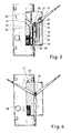
- Fig. 3 is shown schematically the further progress of the assembly of the rotor.
- the rotor blade 12 via a with the transport carriage 28, on which the rotor blade over, for example a fixing belt 31 is fixed, moved on a rail system 35 so that the rotor blade root points in the direction of the center 26.
- the rotor blade root can then be connected to the rotor hub 15.
- the end position is in Fig. 4 shown schematically.
- the rotor blade 14 In this position, in which the blade root of the rotor blade 14 points to the center 26, the rotor blade 14 can be connected to the rotor hub 15. There is then also the deletion or mounting of the machine house 16, as in the transition from Fig. 4 to Fig. 5 is indicated. Finally, the rotor is lifted in the usual way by means of the crane 48 and fixed to the machine house. It is also possible that the respective rotor blade can be pivoted substantially horizontally relative to the transport carriage. As a result, the rotor blades do not collide with each other in the process.
- the respective transport vehicle can for this purpose have a rotation device to which the rotor blade is attached or rests and which is pivotable relative to a lower part of the transport carriage.
- the trolley has an adjusting device with which the rotor blade can be adjusted in the lateral and / or vertical direction to allow a custom-fit mounting in the rotor hub 15.
- Fig. 4 is still the recess 41 in the jack-up barge 40 indicated and the recorded part 43 of the floating body 19 shown hatched. It can be seen that half of the floating body 19 is received in the recess 41.
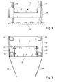
- the recess is in again Fig. 6 shown more clearly. Here it can be seen that the recess of the height makes up about half the height of the jack-up barge 40 and also has a bottom on which the float 19 can rest.
- the jack-up barge 40 has ramped up and is located above the waters of the open sea 18.
- Fig. 7 schematically shows a plan view of the jack-up barge 40 from Fig. 6 , in particular here as well as in Fig. 5 a wave fence 46 is indicated.
- the wave fence 46 can, as in Fig. 5 is shown, in the moment in which the float 19 is received in the recess 41, to be closed. Before the float is introduced, the wave fence 46, as in Fig. 7 is indicated, be open.
- Fig. 7 are still locking devices 45 shown, which can engage in recesses in the float 19, which are not shown.
- Fig. 8 shows a further inventive jack-up barge 41 'in a schematic side view.
- This jack-up barge 41 ' has a continuous recess 42, so a recess which extends over the whole jack-up barge 40'.
- the float 19 is then completely received in the recess 41, or if the float 19 is longer than the width of the jack-up barge, the float 19 can protrude on one side and / or on the other side.
- Fig. 9 The arrangement shown has the advantage that the legs of the jack-up barge 41 'are evenly loaded.
- locking devices 45 and 45 ' are also indicated, which can come into operative connection with the float 19.
- the locking devices 45 are laterally in the float 19 and bring the locking devices 45 'from below.
- the float 19 may preferably transport about 1,000 tons. This then has an empty mass of 250 t to 300 t and dimensions of 50m to 90m x 20m to 30 m.
- FIG. 11 schematically a plan view of a float 19 is shown, on which only the corresponding rotor blades 12-14 are shown with a rotor hub 15.
- the transport position of the rotor blades 12 and 14 are shown in dashed lines.
- the transport position of the rotor blade 13 corresponds to the illustrated position of the rotor blade 13 in FIG Fig. 10 ,
- the further space of the floating body 19 has been occupied with other elements of the wind turbine, such as tower segments and the nacelle, but in the representation of the Fig. 10 already deleted.
- the rotor blade 13 rests on a receiving device 63 which is detachably fixed to the floating body 19.
- the rotor blade 13 thus has the desired mounting position.
- the rotor hub 15 is already mounted or preassembled on the rotor blade 13.
- these are moved on a short travel on the trolley 28 and 29.
- the travel paths are shown by the reference numerals 62 and 62 '.
- the rotor blades 12 and 14, as shown by the pivoting movement 61, 61 ' can also be pivoted.
- Fig. 11 shows a further plan view of a floating body 19, with which a further variant of the assembly of the rotor blades 12-14 is to be shown on a rotor hub 15.
- the rotor blades 12 and 14 on receiving devices 63 and 63 'are applied.
- first dashed the transport position of the rotor blades 12 and 14 is shown. From this transport position, the rotor blades 12 and 14 only have to be pivoted, in each case by 120 ° along the pivoting movement 61 or 61 '.
- the rotor blade 13, which is arranged in the middle, can be arranged either during transport as in Fig. 11 shown. In this case, the rotor blade 13 can not, as in Fig. 11 shown, rest on a transport goods 28, but also on a receiving device which is detachably connected to the float 19. In this case, then the rotor blade 13 does not have to be moved significantly. If the rotor hub 15 is mounted or preassembled on the rotor blade 13, not even an adjusting device on the receiving device 28 is necessary for a linear, horizontal and / or vertical adjustment possibility.
- the rotor blade 13 is shown resting on a trolley 28. During transport, the rotor blade 13 can then also be arranged slightly higher, to lie transversely to the longitudinal axis of the rotor blade 13 approximately at the same height as the rotor blades 12 and 14, in the horizontal plane, ie in plan view of the float 19.
- the rotor blade 13 is first in Fig. 11 Move down, namely according to the movement 62 and then the rotor blades 12 and 14 pivoted by 120 ° along the pivoting movement 61 and 61 '.
- the rotor blades 12 and 14 can be adjusted accordingly for mounting on the rotor hub 15.
- the rotor blade 13 is then already arranged in the mounting position for transport. It is advantageous if the centers of gravity of the rotor blades lie on the indicated center of gravity circle 60.
Landscapes
- Engineering & Computer Science (AREA)
- Life Sciences & Earth Sciences (AREA)
- Sustainable Development (AREA)
- Sustainable Energy (AREA)
- Chemical & Material Sciences (AREA)
- Combustion & Propulsion (AREA)
- Mechanical Engineering (AREA)
- General Engineering & Computer Science (AREA)
- Wind Motors (AREA)
Priority Applications (2)
| Application Number | Priority Date | Filing Date | Title |
|---|---|---|---|
| EP15152947.6A EP2868915B1 (fr) | 2009-03-10 | 2010-03-05 | Plate-forme de montage pour éoliennes |
| DK15152947.6T DK2868915T3 (en) | 2009-03-10 | 2010-03-05 | Wind turbine installation platform |
Applications Claiming Priority (1)
| Application Number | Priority Date | Filing Date | Title |
|---|---|---|---|
| DE102009011915.9A DE102009011915B4 (de) | 2009-03-10 | 2009-03-10 | Verfahren und Anordnung zum Transportieren und zum Montieren von Komponenten einer Windenergieanlage sowie Montage-Plattform |
Related Child Applications (2)
| Application Number | Title | Priority Date | Filing Date |
|---|---|---|---|
| EP15152947.6A Division EP2868915B1 (fr) | 2009-03-10 | 2010-03-05 | Plate-forme de montage pour éoliennes |
| EP15152947.6A Division-Into EP2868915B1 (fr) | 2009-03-10 | 2010-03-05 | Plate-forme de montage pour éoliennes |
Publications (3)
| Publication Number | Publication Date |
|---|---|
| EP2228533A2 true EP2228533A2 (fr) | 2010-09-15 |
| EP2228533A3 EP2228533A3 (fr) | 2011-11-23 |
| EP2228533B1 EP2228533B1 (fr) | 2015-05-13 |
Family
ID=42072834
Family Applications (2)
| Application Number | Title | Priority Date | Filing Date |
|---|---|---|---|
| EP15152947.6A Not-in-force EP2868915B1 (fr) | 2009-03-10 | 2010-03-05 | Plate-forme de montage pour éoliennes |
| EP10155598.5A Not-in-force EP2228533B1 (fr) | 2009-03-10 | 2010-03-05 | Procédé et ensemble de transport de composants d'une éolienne et plate-forme de montage |
Family Applications Before (1)
| Application Number | Title | Priority Date | Filing Date |
|---|---|---|---|
| EP15152947.6A Not-in-force EP2868915B1 (fr) | 2009-03-10 | 2010-03-05 | Plate-forme de montage pour éoliennes |
Country Status (4)
| Country | Link |
|---|---|
| EP (2) | EP2868915B1 (fr) |
| DE (1) | DE102009011915B4 (fr) |
| DK (2) | DK2228533T3 (fr) |
| ES (2) | ES2559837T3 (fr) |
Cited By (3)
| Publication number | Priority date | Publication date | Assignee | Title |
|---|---|---|---|---|
| JP2012122481A (ja) * | 2010-12-08 | 2012-06-28 | Siemens Ag | 風車ロータを輸送するための装置および方法 |
| EP2532879A1 (fr) * | 2011-06-07 | 2012-12-12 | Siemens Aktiengesellschaft | Montage et/ou maintenance d'une éolienne |
| EP3382195A1 (fr) * | 2017-03-30 | 2018-10-03 | Senvion GmbH | Utilisation des moyens de transport lors de la construction des éoliennes et aide au montage |
Families Citing this family (2)
| Publication number | Priority date | Publication date | Assignee | Title |
|---|---|---|---|---|
| DE102020108154B3 (de) * | 2020-03-25 | 2021-04-08 | Aerodyn Consulting Singapore Pte Ltd | Vorrichtung und Verfahren zum Errichten einer Windenergieanlage mit einem Turm und zwei sich vom Turm erstreckenden Auslegern |
| US11168666B1 (en) | 2020-10-29 | 2021-11-09 | Deme Offshore Be Nv | Jack-up platform with receiving space for a barge and method for offshore installation of a wind turbine |
Citations (3)
| Publication number | Priority date | Publication date | Assignee | Title |
|---|---|---|---|---|
| US20050163616A1 (en) | 2002-05-27 | 2005-07-28 | Mortensen Henrik K. | Methods of mounting a wind turbine, a wind turbine foundation and a wind turbine assembly |
| EP1356205B1 (fr) | 2000-12-13 | 2007-02-28 | Mammoet Marine B.V.I.O. | Procede et dispositif pour la mise en place d'au moins une eolienne en mer libre |
| DE102007012848A1 (de) | 2007-03-17 | 2008-09-18 | Aerodyn Engineering Gmbh | Verfahren zum Transport, Errichten und Austausch einer Gondel inkl. Rotor einer Offshore-Windenergieanlage und Wasserfahrzeug zur Durchführung des Verfahrens |
Family Cites Families (4)
| Publication number | Priority date | Publication date | Assignee | Title |
|---|---|---|---|---|
| US3734046A (en) * | 1971-05-10 | 1973-05-22 | Carswell L Manuf Co Firman | Floating dry dock |
| GB2090894B (en) * | 1981-01-13 | 1984-05-23 | Ocean Drilling Exploration | Method of constructing an off shore tower and tower so constructed |
| DE10021163B4 (de) * | 2000-04-29 | 2006-03-02 | Aerodyn Engineering Gmbh | Wasserfahrzeug zum Versorgen einer Offshore-Windenergieanlage |
| PT1518053E (pt) * | 2002-05-28 | 2009-01-09 | Iti Scotland Ltd | Método e guindaste para a instalação, manutenção e desactivação de turbinas eólicas |
-
2009
- 2009-03-10 DE DE102009011915.9A patent/DE102009011915B4/de not_active Expired - Fee Related
-
2010
- 2010-03-05 ES ES15152947.6T patent/ES2559837T3/es active Active
- 2010-03-05 ES ES10155598.5T patent/ES2543208T3/es active Active
- 2010-03-05 DK DK10155598.5T patent/DK2228533T3/da active
- 2010-03-05 DK DK15152947.6T patent/DK2868915T3/en active
- 2010-03-05 EP EP15152947.6A patent/EP2868915B1/fr not_active Not-in-force
- 2010-03-05 EP EP10155598.5A patent/EP2228533B1/fr not_active Not-in-force
Patent Citations (3)
| Publication number | Priority date | Publication date | Assignee | Title |
|---|---|---|---|---|
| EP1356205B1 (fr) | 2000-12-13 | 2007-02-28 | Mammoet Marine B.V.I.O. | Procede et dispositif pour la mise en place d'au moins une eolienne en mer libre |
| US20050163616A1 (en) | 2002-05-27 | 2005-07-28 | Mortensen Henrik K. | Methods of mounting a wind turbine, a wind turbine foundation and a wind turbine assembly |
| DE102007012848A1 (de) | 2007-03-17 | 2008-09-18 | Aerodyn Engineering Gmbh | Verfahren zum Transport, Errichten und Austausch einer Gondel inkl. Rotor einer Offshore-Windenergieanlage und Wasserfahrzeug zur Durchführung des Verfahrens |
Non-Patent Citations (1)
| Title |
|---|
| VON ERICH HAU: "Wind Turbines", 2006, SPRINGER-VERLAG, pages: 646 - 649 |
Cited By (7)
| Publication number | Priority date | Publication date | Assignee | Title |
|---|---|---|---|---|
| JP2012122481A (ja) * | 2010-12-08 | 2012-06-28 | Siemens Ag | 風車ロータを輸送するための装置および方法 |
| CN102536679A (zh) * | 2010-12-08 | 2012-07-04 | 西门子公司 | 用于运输风力涡轮机转子的布置结构和方法 |
| CN102536679B (zh) * | 2010-12-08 | 2015-05-20 | 西门子公司 | 用于运输风力涡轮机转子的布置结构和方法 |
| EP2532879A1 (fr) * | 2011-06-07 | 2012-12-12 | Siemens Aktiengesellschaft | Montage et/ou maintenance d'une éolienne |
| CN102817790A (zh) * | 2011-06-07 | 2012-12-12 | 西门子公司 | 风力涡轮机的组装和/或维修 |
| CN102817790B (zh) * | 2011-06-07 | 2016-11-23 | 西门子公司 | 风力涡轮机的组装和/或维修 |
| EP3382195A1 (fr) * | 2017-03-30 | 2018-10-03 | Senvion GmbH | Utilisation des moyens de transport lors de la construction des éoliennes et aide au montage |
Also Published As
| Publication number | Publication date |
|---|---|
| DK2228533T3 (da) | 2015-07-27 |
| EP2868915A1 (fr) | 2015-05-06 |
| EP2228533A3 (fr) | 2011-11-23 |
| DE102009011915A1 (de) | 2010-09-16 |
| EP2228533B1 (fr) | 2015-05-13 |
| DE102009011915B4 (de) | 2018-02-01 |
| EP2868915B1 (fr) | 2015-11-04 |
| ES2559837T3 (es) | 2016-02-16 |
| DK2868915T3 (en) | 2016-02-08 |
| ES2543208T3 (es) | 2015-08-17 |
Similar Documents
| Publication | Publication Date | Title |
|---|---|---|
| EP2129906B1 (fr) | Procédé pour remplacer une nacelle comportant le rotor d'une éolienne offshore et navire servant à la mise en oeuvre de ce procédé | |
| EP3019740B1 (fr) | Éolienne flottante à base flottante et procédé d'installation d'une éolienne flottante de ce type | |
| EP2539219B1 (fr) | Dispositif pour le transport et l'installation d'un agencement d'une éolienne offshore comprenant une embase et procédé pour le transport et l'installation d'un tel agencement muni d'une embase | |
| DE10205988B4 (de) | Windenergieanlage | |
| WO2010028762A2 (fr) | Dispositif pour le transport et l'installation d'un système d'éolienne offshore comprenant au moins une embase et procédé pour le transport et l'installation d'une telle embase munie d'un mât | |
| WO2001083290A1 (fr) | Bateau destine a la maintenance d'une centrale eolienne situee en mer | |
| EP2868915B1 (fr) | Plate-forme de montage pour éoliennes | |
| DE102011112425B4 (de) | Installationsfahrzeug für ein Gezeitenkraftwerk und Verfahren für dessen Betrieb | |
| DE10332382B4 (de) | Aufstellvorrichtung für eine Windenergieanlage, Wasserfahrzeug zum Transport einer Aufstellvorrichtung sowie Verfahren zum Aufstellen einer Off-Shore-Windenergieanlage | |
| EP4127453B1 (fr) | Procédé de montage d'une éolienne comprenant une tour et deux flèches s'étendant à partir de la tour | |
| WO2009018946A2 (fr) | Installation de production d'énergie plongeante abordable dans deux directions | |
| DE202021102426U1 (de) | Off-Shore-Windenergieanlagen-Aufbau-Schiff | |
| EP2396537B1 (fr) | Équipement et procédé pour la fabrication d'installations aérogénératrices en mer | |
| DE102010015412A1 (de) | Verfahren zum Transport und zur Montage einer Windkraftanlage und Transport- und Montagesystem | |
| DE102021111680A1 (de) | Off-shore-windenergieanlagen-aufbau-schiff sowie off-shorewindenergieanlagen- aufbau-verfahren | |
| DE10162225A1 (de) | Schwimmfähige Hubplattform zum Transport von Offshore-Windenergieanlagen | |
| EP1384883B1 (fr) | Barge de transport pour nacelles d'éoliennes marines et procédé associé | |
| DE202004021468U1 (de) | Vorrichtung zum Transport und Errichtung einer Windkraftanlage | |
| EP1321669B1 (fr) | Système de transport et d'installation d'éoliennes marines | |
| EP1634998A1 (fr) | Transport et fondation d'unités fonctionelles, en particulier d'éoliennes marines. | |
| WO2010028763A2 (fr) | Installation de production pour des éoliennes offshore et procédé pour produire au moins un module d'éolienne offshore | |
| DE102018105545B4 (de) | Bootsfahrstuhl | |
| DE3001735C2 (de) | Einrichtung zum automatischen Zusammensetzen und Zerlegen eines aus mehreren Behälterteilen bestehenden Pontons | |
| DE102013005029A1 (de) | Unterwasser-Strömungskraftwerk |
Legal Events
| Date | Code | Title | Description |
|---|---|---|---|
| PUAI | Public reference made under article 153(3) epc to a published international application that has entered the european phase |
Free format text: ORIGINAL CODE: 0009012 |
|
| AK | Designated contracting states |
Kind code of ref document: A2 Designated state(s): AT BE BG CH CY CZ DE DK EE ES FI FR GB GR HR HU IE IS IT LI LT LU LV MC MK MT NL NO PL PT RO SE SI SK SM TR |
|
| AX | Request for extension of the european patent |
Extension state: AL BA ME RS |
|
| PUAL | Search report despatched |
Free format text: ORIGINAL CODE: 0009013 |
|
| AK | Designated contracting states |
Kind code of ref document: A3 Designated state(s): AT BE BG CH CY CZ DE DK EE ES FI FR GB GR HR HU IE IS IT LI LT LU LV MC MK MT NL NO PL PT RO SE SI SK SM TR |
|
| AX | Request for extension of the european patent |
Extension state: AL BA ME RS |
|
| RIC1 | Information provided on ipc code assigned before grant |
Ipc: F03D 1/00 20060101AFI20111019BHEP Ipc: F03D 1/06 20060101ALI20111019BHEP |
|
| 17P | Request for examination filed |
Effective date: 20120519 |
|
| RAP1 | Party data changed (applicant data changed or rights of an application transferred) |
Owner name: REPOWER SYSTEMS SE |
|
| 17Q | First examination report despatched |
Effective date: 20140729 |
|
| RAP1 | Party data changed (applicant data changed or rights of an application transferred) |
Owner name: SENVION SE |
|
| GRAP | Despatch of communication of intention to grant a patent |
Free format text: ORIGINAL CODE: EPIDOSNIGR1 |
|
| INTG | Intention to grant announced |
Effective date: 20150105 |
|
| GRAS | Grant fee paid |
Free format text: ORIGINAL CODE: EPIDOSNIGR3 |
|
| GRAA | (expected) grant |
Free format text: ORIGINAL CODE: 0009210 |
|
| AK | Designated contracting states |
Kind code of ref document: B1 Designated state(s): AT BE BG CH CY CZ DE DK EE ES FI FR GB GR HR HU IE IS IT LI LT LU LV MC MK MT NL NO PL PT RO SE SI SK SM TR |
|
| REG | Reference to a national code |
Ref country code: GB Ref legal event code: FG4D Free format text: NOT ENGLISH |
|
| REG | Reference to a national code |
Ref country code: CH Ref legal event code: EP |
|
| REG | Reference to a national code |
Ref country code: IE Ref legal event code: FG4D Free format text: LANGUAGE OF EP DOCUMENT: GERMAN |
|
| REG | Reference to a national code |
Ref country code: AT Ref legal event code: REF Ref document number: 726957 Country of ref document: AT Kind code of ref document: T Effective date: 20150615 |
|
| REG | Reference to a national code |
Ref country code: DE Ref legal event code: R096 Ref document number: 502010009516 Country of ref document: DE Effective date: 20150625 |
|
| REG | Reference to a national code |
Ref country code: DK Ref legal event code: T3 Effective date: 20150720 |
|
| REG | Reference to a national code |
Ref country code: ES Ref legal event code: FG2A Ref document number: 2543208 Country of ref document: ES Kind code of ref document: T3 Effective date: 20150817 Ref country code: DE Ref legal event code: R082 Ref document number: 502010009516 Country of ref document: DE Representative=s name: PATENTANWAELTE SEEMANN & PARTNER, DE Ref country code: DE Ref legal event code: R081 Ref document number: 502010009516 Country of ref document: DE Owner name: SENVION GMBH, DE Free format text: FORMER OWNER: SENVION SE, 22297 HAMBURG, DE Ref country code: DE Ref legal event code: R082 Ref document number: 502010009516 Country of ref document: DE Representative=s name: SEEMANN & PARTNER PATENTANWAELTE MBB, DE Ref country code: DE Ref legal event code: R082 Ref document number: 502010009516 Country of ref document: DE Representative=s name: WALLINGER RICKER SCHLOTTER TOSTMANN PATENT- UN, DE |
|
| RAP2 | Party data changed (patent owner data changed or rights of a patent transferred) |
Owner name: SENVION GMBH |
|
| REG | Reference to a national code |
Ref country code: NL Ref legal event code: MP Effective date: 20150513 |
|
| REG | Reference to a national code |
Ref country code: LT Ref legal event code: MG4D |
|
| PG25 | Lapsed in a contracting state [announced via postgrant information from national office to epo] |
Ref country code: LT Free format text: LAPSE BECAUSE OF FAILURE TO SUBMIT A TRANSLATION OF THE DESCRIPTION OR TO PAY THE FEE WITHIN THE PRESCRIBED TIME-LIMIT Effective date: 20150513 Ref country code: NO Free format text: LAPSE BECAUSE OF FAILURE TO SUBMIT A TRANSLATION OF THE DESCRIPTION OR TO PAY THE FEE WITHIN THE PRESCRIBED TIME-LIMIT Effective date: 20150813 Ref country code: PT Free format text: LAPSE BECAUSE OF FAILURE TO SUBMIT A TRANSLATION OF THE DESCRIPTION OR TO PAY THE FEE WITHIN THE PRESCRIBED TIME-LIMIT Effective date: 20150914 Ref country code: FI Free format text: LAPSE BECAUSE OF FAILURE TO SUBMIT A TRANSLATION OF THE DESCRIPTION OR TO PAY THE FEE WITHIN THE PRESCRIBED TIME-LIMIT Effective date: 20150513 Ref country code: HR Free format text: LAPSE BECAUSE OF FAILURE TO SUBMIT A TRANSLATION OF THE DESCRIPTION OR TO PAY THE FEE WITHIN THE PRESCRIBED TIME-LIMIT Effective date: 20150513 |
|
| REG | Reference to a national code |
Ref country code: AT Ref legal event code: HC Ref document number: 726957 Country of ref document: AT Kind code of ref document: T Owner name: SENVION GMBH, DE Effective date: 20150923 |
|
| PG25 | Lapsed in a contracting state [announced via postgrant information from national office to epo] |
Ref country code: LV Free format text: LAPSE BECAUSE OF FAILURE TO SUBMIT A TRANSLATION OF THE DESCRIPTION OR TO PAY THE FEE WITHIN THE PRESCRIBED TIME-LIMIT Effective date: 20150513 Ref country code: IS Free format text: LAPSE BECAUSE OF FAILURE TO SUBMIT A TRANSLATION OF THE DESCRIPTION OR TO PAY THE FEE WITHIN THE PRESCRIBED TIME-LIMIT Effective date: 20150913 Ref country code: BG Free format text: LAPSE BECAUSE OF FAILURE TO SUBMIT A TRANSLATION OF THE DESCRIPTION OR TO PAY THE FEE WITHIN THE PRESCRIBED TIME-LIMIT Effective date: 20150813 Ref country code: GR Free format text: LAPSE BECAUSE OF FAILURE TO SUBMIT A TRANSLATION OF THE DESCRIPTION OR TO PAY THE FEE WITHIN THE PRESCRIBED TIME-LIMIT Effective date: 20150814 |
|
| PG25 | Lapsed in a contracting state [announced via postgrant information from national office to epo] |
Ref country code: EE Free format text: LAPSE BECAUSE OF FAILURE TO SUBMIT A TRANSLATION OF THE DESCRIPTION OR TO PAY THE FEE WITHIN THE PRESCRIBED TIME-LIMIT Effective date: 20150513 |
|
| REG | Reference to a national code |
Ref country code: DE Ref legal event code: R097 Ref document number: 502010009516 Country of ref document: DE |
|
| PG25 | Lapsed in a contracting state [announced via postgrant information from national office to epo] |
Ref country code: CZ Free format text: LAPSE BECAUSE OF FAILURE TO SUBMIT A TRANSLATION OF THE DESCRIPTION OR TO PAY THE FEE WITHIN THE PRESCRIBED TIME-LIMIT Effective date: 20150513 Ref country code: SK Free format text: LAPSE BECAUSE OF FAILURE TO SUBMIT A TRANSLATION OF THE DESCRIPTION OR TO PAY THE FEE WITHIN THE PRESCRIBED TIME-LIMIT Effective date: 20150513 Ref country code: RO Free format text: LAPSE BECAUSE OF NON-PAYMENT OF DUE FEES Effective date: 20150513 Ref country code: PL Free format text: LAPSE BECAUSE OF FAILURE TO SUBMIT A TRANSLATION OF THE DESCRIPTION OR TO PAY THE FEE WITHIN THE PRESCRIBED TIME-LIMIT Effective date: 20150513 |
|
| PLBE | No opposition filed within time limit |
Free format text: ORIGINAL CODE: 0009261 |
|
| STAA | Information on the status of an ep patent application or granted ep patent |
Free format text: STATUS: NO OPPOSITION FILED WITHIN TIME LIMIT |
|
| REG | Reference to a national code |
Ref country code: FR Ref legal event code: PLFP Year of fee payment: 7 |
|
| 26N | No opposition filed |
Effective date: 20160216 |
|
| PG25 | Lapsed in a contracting state [announced via postgrant information from national office to epo] |
Ref country code: IT Free format text: LAPSE BECAUSE OF FAILURE TO SUBMIT A TRANSLATION OF THE DESCRIPTION OR TO PAY THE FEE WITHIN THE PRESCRIBED TIME-LIMIT Effective date: 20150513 |
|
| PG25 | Lapsed in a contracting state [announced via postgrant information from national office to epo] |
Ref country code: SI Free format text: LAPSE BECAUSE OF FAILURE TO SUBMIT A TRANSLATION OF THE DESCRIPTION OR TO PAY THE FEE WITHIN THE PRESCRIBED TIME-LIMIT Effective date: 20150513 |
|
| PG25 | Lapsed in a contracting state [announced via postgrant information from national office to epo] |
Ref country code: BE Free format text: LAPSE BECAUSE OF NON-PAYMENT OF DUE FEES Effective date: 20160331 |
|
| PG25 | Lapsed in a contracting state [announced via postgrant information from national office to epo] |
Ref country code: MC Free format text: LAPSE BECAUSE OF FAILURE TO SUBMIT A TRANSLATION OF THE DESCRIPTION OR TO PAY THE FEE WITHIN THE PRESCRIBED TIME-LIMIT Effective date: 20150513 Ref country code: LU Free format text: LAPSE BECAUSE OF FAILURE TO SUBMIT A TRANSLATION OF THE DESCRIPTION OR TO PAY THE FEE WITHIN THE PRESCRIBED TIME-LIMIT Effective date: 20160305 |
|
| REG | Reference to a national code |
Ref country code: CH Ref legal event code: PL |
|
| REG | Reference to a national code |
Ref country code: IE Ref legal event code: MM4A |
|
| PG25 | Lapsed in a contracting state [announced via postgrant information from national office to epo] |
Ref country code: LI Free format text: LAPSE BECAUSE OF NON-PAYMENT OF DUE FEES Effective date: 20160331 Ref country code: CH Free format text: LAPSE BECAUSE OF NON-PAYMENT OF DUE FEES Effective date: 20160331 Ref country code: IE Free format text: LAPSE BECAUSE OF NON-PAYMENT OF DUE FEES Effective date: 20160305 |
|
| REG | Reference to a national code |
Ref country code: FR Ref legal event code: PLFP Year of fee payment: 8 |
|
| REG | Reference to a national code |
Ref country code: AT Ref legal event code: MM01 Ref document number: 726957 Country of ref document: AT Kind code of ref document: T Effective date: 20160305 |
|
| PG25 | Lapsed in a contracting state [announced via postgrant information from national office to epo] |
Ref country code: NL Free format text: LAPSE BECAUSE OF FAILURE TO SUBMIT A TRANSLATION OF THE DESCRIPTION OR TO PAY THE FEE WITHIN THE PRESCRIBED TIME-LIMIT Effective date: 20150513 Ref country code: SE Free format text: LAPSE BECAUSE OF FAILURE TO SUBMIT A TRANSLATION OF THE DESCRIPTION OR TO PAY THE FEE WITHIN THE PRESCRIBED TIME-LIMIT Effective date: 20150513 |
|
| PG25 | Lapsed in a contracting state [announced via postgrant information from national office to epo] |
Ref country code: MT Free format text: LAPSE BECAUSE OF FAILURE TO SUBMIT A TRANSLATION OF THE DESCRIPTION OR TO PAY THE FEE WITHIN THE PRESCRIBED TIME-LIMIT Effective date: 20150513 Ref country code: AT Free format text: LAPSE BECAUSE OF NON-PAYMENT OF DUE FEES Effective date: 20160305 |
|
| REG | Reference to a national code |
Ref country code: DE Ref legal event code: R082 Ref document number: 502010009516 Country of ref document: DE Representative=s name: WALLINGER RICKER SCHLOTTER TOSTMANN PATENT- UN, DE |
|
| REG | Reference to a national code |
Ref country code: FR Ref legal event code: PLFP Year of fee payment: 9 |
|
| PG25 | Lapsed in a contracting state [announced via postgrant information from national office to epo] |
Ref country code: CY Free format text: LAPSE BECAUSE OF FAILURE TO SUBMIT A TRANSLATION OF THE DESCRIPTION OR TO PAY THE FEE WITHIN THE PRESCRIBED TIME-LIMIT Effective date: 20150513 Ref country code: SM Free format text: LAPSE BECAUSE OF FAILURE TO SUBMIT A TRANSLATION OF THE DESCRIPTION OR TO PAY THE FEE WITHIN THE PRESCRIBED TIME-LIMIT Effective date: 20150513 Ref country code: HU Free format text: LAPSE BECAUSE OF FAILURE TO SUBMIT A TRANSLATION OF THE DESCRIPTION OR TO PAY THE FEE WITHIN THE PRESCRIBED TIME-LIMIT; INVALID AB INITIO Effective date: 20100305 |
|
| PG25 | Lapsed in a contracting state [announced via postgrant information from national office to epo] |
Ref country code: MK Free format text: LAPSE BECAUSE OF FAILURE TO SUBMIT A TRANSLATION OF THE DESCRIPTION OR TO PAY THE FEE WITHIN THE PRESCRIBED TIME-LIMIT Effective date: 20150513 Ref country code: TR Free format text: LAPSE BECAUSE OF FAILURE TO SUBMIT A TRANSLATION OF THE DESCRIPTION OR TO PAY THE FEE WITHIN THE PRESCRIBED TIME-LIMIT Effective date: 20150513 |
|
| PGFP | Annual fee paid to national office [announced via postgrant information from national office to epo] |
Ref country code: GB Payment date: 20200325 Year of fee payment: 11 Ref country code: DK Payment date: 20200323 Year of fee payment: 11 Ref country code: DE Payment date: 20200324 Year of fee payment: 11 |
|
| PGFP | Annual fee paid to national office [announced via postgrant information from national office to epo] |
Ref country code: FR Payment date: 20200324 Year of fee payment: 11 |
|
| PGFP | Annual fee paid to national office [announced via postgrant information from national office to epo] |
Ref country code: ES Payment date: 20200421 Year of fee payment: 11 |
|
| REG | Reference to a national code |
Ref country code: DE Ref legal event code: R119 Ref document number: 502010009516 Country of ref document: DE |
|
| REG | Reference to a national code |
Ref country code: DK Ref legal event code: EBP Effective date: 20210331 |
|
| GBPC | Gb: european patent ceased through non-payment of renewal fee |
Effective date: 20210305 |
|
| PG25 | Lapsed in a contracting state [announced via postgrant information from national office to epo] |
Ref country code: FR Free format text: LAPSE BECAUSE OF NON-PAYMENT OF DUE FEES Effective date: 20210331 Ref country code: GB Free format text: LAPSE BECAUSE OF NON-PAYMENT OF DUE FEES Effective date: 20210305 Ref country code: DE Free format text: LAPSE BECAUSE OF NON-PAYMENT OF DUE FEES Effective date: 20211001 |
|
| PG25 | Lapsed in a contracting state [announced via postgrant information from national office to epo] |
Ref country code: DK Free format text: LAPSE BECAUSE OF NON-PAYMENT OF DUE FEES Effective date: 20210331 |
|
| REG | Reference to a national code |
Ref country code: ES Ref legal event code: FD2A Effective date: 20220523 |
|
| PG25 | Lapsed in a contracting state [announced via postgrant information from national office to epo] |
Ref country code: ES Free format text: LAPSE BECAUSE OF NON-PAYMENT OF DUE FEES Effective date: 20210306 |