EP2228660A2 - Déclenchement de bitmaps du domaine de fréquence à l'aide d'un déclenchement basé sur la couleur, la densité et la corrélation - Google Patents
Déclenchement de bitmaps du domaine de fréquence à l'aide d'un déclenchement basé sur la couleur, la densité et la corrélation Download PDFInfo
- Publication number
- EP2228660A2 EP2228660A2 EP10156407A EP10156407A EP2228660A2 EP 2228660 A2 EP2228660 A2 EP 2228660A2 EP 10156407 A EP10156407 A EP 10156407A EP 10156407 A EP10156407 A EP 10156407A EP 2228660 A2 EP2228660 A2 EP 2228660A2
- Authority
- EP
- European Patent Office
- Prior art keywords
- frequency domain
- interest
- bitmap
- region
- time
- Prior art date
- Legal status (The legal status is an assumption and is not a legal conclusion. Google has not performed a legal analysis and makes no representation as to the accuracy of the status listed.)
- Granted
Links
Images


Classifications
-
- G—PHYSICS
- G01—MEASURING; TESTING
- G01R—MEASURING ELECTRIC VARIABLES; MEASURING MAGNETIC VARIABLES
- G01R23/00—Arrangements for measuring frequencies; Arrangements for analysing frequency spectra
- G01R23/16—Spectrum analysis; Fourier analysis
-
- G—PHYSICS
- G01—MEASURING; TESTING
- G01R—MEASURING ELECTRIC VARIABLES; MEASURING MAGNETIC VARIABLES
- G01R13/00—Arrangements for displaying electric variables or waveforms
- G01R13/02—Arrangements for displaying electric variables or waveforms for displaying measured electric variables in digital form
- G01R13/0218—Circuits therefor
- G01R13/0254—Circuits therefor for triggering, synchronisation
- G01R13/0263—Circuits therefor for triggering, synchronisation for non-recurrent functions, e.g. transients
Definitions
- test and measurement devices exist for use in connection with RF signals.
- these devices include components that provide real-time processing and other functionality that occurs as a time-varying signal is received, and other components that perform off-line functionality, such as a detailed signal analysis that occurs after a signal event has been captured and stored.
- Test and measurement operations are often controlled using triggering methods. For example, in the above case of discovering and capturing signal events for subsequent study, signal captures can be based on a trigger that is activated when certain signal characteristics are detected. Use of such a trigger conserves computing resources by only capturing signals that may potentially be of interest.
- FIG. 1 is a schematic depiction of a test and measurement system according to the present description.
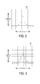
- FIGS. 2 and 3 are schematic depictions of exemplary frequency spectrum bitmaps.
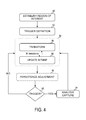
- FIG. 4 shows an exemplary method for maintaining a frequency spectrum bitmap and performing triggers in response to bitmap data.
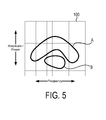
- FIG. 5 shows an exemplary frequency spectrum bitmap, including two different regions which may incur different waveform prevalence/density.
- FIGS. 6 - 8 show exemplary frequency spectrum bitmaps with bitmap samples correlating variously to a reference signal event.
- FIG. 9 is a schematic depiction of various bitmaps that may be employed in connection with the systems and methods of the present description.
- FIG. 10 shows a user interface system and method for creating frequency spectrum bitmap triggers.
- System 20 includes a front end 22 for receiving a time-varying signal 24 and for optionally performing various processing operations on the incoming signal.
- Optional processing may include filtering, mixing, down-conversion, etc.
- additional components 26 may be employed to convert the incoming signal into digital form, and to perform decimation operations and/or make phase and amplitude corrections.
- the depicted configuration is exemplary, and those skilled in the art will appreciate that a variety of other arrangements may be employed.
- the signal(s) exists as a digitally processed version of time-varying signal 24.
- This is applied to real-time engine processing block 30.
- block 30 is configured to repeatedly generate digital frequency domain spectrums 31 based on the time-varying signal 24. Spectrum generation may be performed using any number of digital frequency transform techniques, including chirp-z, FFT and variable-length FFT.
- System 20 also includes a memory subsystem 32, which is operatively coupled (e.g., via a bus) with the front-end blocks and the real time block 30. Furthermore, system 20 typically also includes a display subsystem 34 and a processing subsystem 36. As discussed further below, memory subsystem 32 may provide a data store containing a frequency domain bitmap constructed from spectrums 31. System 20 may also include physically or logically separate storage location 38, which may be employed for storage of signals that will be subjected to detailed offline analysis.
- memory subsystem 32 is configured to provide memory space for supporting real-time functionality of system 20.
- a portion of time-varying signal 24 typically is retained in memory while frequency domain transformation and other real-time operations are performed at block 30.
- One reason for the retention is to enable a portion of the time-varying signal to be captured and analyzed more extensively offline, for example using processing operations that are more intensive and resource-consumptive than could be performed during real time processing.
- Setting aside a portion of the time-varying signal in this manner may be referred to as an "analysis capture.”
- Such a set-aside typically is done in response to detection of a triggering event, as will be explained in more detail below.
- the real time block 30 operates as a screening tool for making decisions about when a more comprehensive analysis should be performed, and on what specific data it should be performed on. Furthermore, triggering can provide substantial efficiency for users, by eliminating trial and error associated with capturing data of interest, and/or by eliminating the need to capture and sift through large amounts of raw or processed data to find signals of interest.
- frequency domain data is stored in a bitmap structure 40, in which quantized power level information is expressed as a function of frequency.
- bitmap structure 40 in which quantized power level information is expressed as a function of frequency.
- information from a plurality of the digital frequency domain spectrums 31 will be accumulated into the bitmap data structure.
- the bitmap structure 40 is updated and incremented through repeated successive application of the digital frequency domain spectrums as they are generated by block 30.
- the bitmap typically is generated using a high transform rate, which is desirable in many settings to facilitate detection of infrequent events. Though desirable for event detection, the high rate will often be too fast for the display device or devices used in connection with subsystem 34 to display the bitmap data, and will normally be well beyond what human eyes can perceive. Accordingly, the incoming transforms are written into the database at full speed and then transferred to the screen at a viewable rate. For example, the display may be driven by sampling the database 10, 20, 30 or 60 times a second. These are but examples - other frame rates may be employed.
- bitmap structure may be thought of as a grid created by dividing a spectrum graph into rows representing trace amplitude (power) values and columns for points or ranges on the frequency axis. Each cell in the grid contains a count of how many times it was hit by an incoming spectrum. By tracking these counts, the system can implement proportionality to allow the user to visually distinguish rare transients from normal signals and background noise.
- bitmap figures herein provide simplified demonstrative examples, and that the actual embodiment of the database(s) stored in memory subsystem 32 will likely contain hundreds of columns and rows.
- FIG. 2 shows the relationship between a single digital domain frequency transform and the accumulation of many such transforms into the bitmap database. No accumulation has occurred with respect to Fig. 2 - it shows a bitmap representation of a single frequency transform, and indicates the power level of the transform for each frequency in the range of interest. More specifically, Fig. 2 shows what the bitmap cells might contain after a single spectrum is mapped into it. Blank cells contain the value zero, meaning that no points from a spectrum have fallen into them yet.
- the bitmap representation 42 of Fig. 3 shows a bitmap that has been updated (incremented) by applying and storing nine different digital frequency domain transformations in the bitmap. More particularly, the bitmap of Fig. 3 includes the data from the spectrum shown in Fig. 2 , but with eight additional spectrums added. The nature of the spectrums applied to the bitmap is that, for each spectrum, some amplitude/power value is indicated for each value along the frequency axis, even if it is a noise floor or other baseline value, or even a value set aside to represent "invalid point". Indeed, in the example of Fig. 3 , one of the spectrums was generated while the incoming time-varying signal was absent, as reflected by the string of "1" values at the noise floor.
- occurrence values In some cases it will be desirable to map occurrence values to a color scale, in order to provide an enhanced visual representation of the data.
- the following color mapping could be used for the nine-spectrum example described above: Number of Occurrences Color 0 Black 1 Blue 2 Light blue 3 Cyan 4 Green blue 5 Green 6 Yellow 7 Orange 8 Red orange 9 Red In this example, warmer colors such as red, orange etc. are used to indicate higher numbers of occurrences. This is but an example - a variety of other intensity-grading schemes can be used.
- Bitmap hit counts typically are accumulated over time. Because the rate at which spectrums arrive is faster than the display system typically can handle, a "frame" of spectrums (e.g., thousands of spectrums) is accumulated into the bitmap before the next operations are performed on the bitmap. For example, in one embodiment, 48,000 spectrums are applied to the bitmap database each second. Using a frame rate of approximately 33 times per second, the result is that approximately 1400 spectrums are applied to the bitmap database during each display frame. In another embodiment, 292,000 transforms per second are generated, and a 20 Hz frame rate is employed, such that approximately 15,000 spectrums are applied to the bitmap per display frame.
- a "frame" of spectrums e.g., thousands of spectrums
- persistence Maintaining the count values from one frame to the next may be referred to as persistence.
- existing counts in the bitmap database are maintained and the power/frequency values of the newly-arriving spectrums are added to increment the counts, rather than simply restarting the counts and replacing them with the values from the most recent frame.
- Infinite persistence refers to maintaining the full accumulated count from each frame to the next, with each succeeding frame adding to the existing counts.
- variable persistence refers to maintaining less than the full count, which can be implemented in various ways, such as by reducing the count by a fixed fraction for each successive display frame.
- One situation illustrating persistence and its potential utility is an anomalous signal arising only once during a period of observation. Assume that this signal, although present only once, was present for all 1465 of the spectrum updates in a frame. Assume further that a variable persistence scheme is employed in which the bitmap counts are decremented by 25% each frame. In this example, the affected cells in the bitmap would start out with a value of 1465 and would be displayed full-force when the bitmap database was sampled for display of that initial frame. One frame later, the occurrence values in the affected cells would be decremented by 25% to 1099. Another frame later, they would be decremented to 824, and then smaller and smaller until they become so dim as to be invisible.
- a bright trace would be displayed initially with a spike at the signal frequency.
- the part of the displayed spectrum where the signal occurred would diminish (e.g., by fading and/or changing to colors indicating lower density).
- the pixels at the noise level would start to brighten below the fading signal. In the end, only a baseline trace would exist at the noise floor.
- the spectrum measurement systems and methods described above can provide numerous advantages in a variety of settings. Samples from the time-varying signal are converted into spectrum traces at a high rate so that there is little or no dead time between waveform updates. Furthermore, the spectrum traces are fed to a bitmap database that can be implemented with adjustable parameters to boost the visibility of signal events. As described above, persistence may be implemented in various ways, and the waveform prevalence in different portions of the spectrum may be reflected in the display using various intensity grading and color schemes in connection with the bitmap.
- analog frequency domain spectrums could be sampled and processed so as to produce repeated update of a bitmap data structure. Though the particulars of such a scheme might vary, the general effect would be to provide digitized versions of the analog spectrums. Thus, for purposes of the present discussion, the analog spectrums would yield a plurality of digital frequency domain spectrums (through conversion) that would be repeatedly applied to update the bitmap database.
- triggering methods exist, including various types of external and internal triggers, including level triggering, power triggers, frequency mask triggers and the like.
- level triggering triggering
- power triggers triggering
- frequency mask triggers triggering methods
- a trigger is declared, an analysis capture of the time-varying signal is taken using various acquisition settings, such as capture length, delay, etc.
- the existing triggers are adequate for a fairly wide variety of signals, there is a signal situation that is relative common in digital RF systems for which none of the existing internals triggering methods work. For example, in a given frequency range, signals may occur at a variety of different power levels at different times.
- a power trigger can catch signals with the highest power
- frequency mask triggers can catch signals that exceed some power threshold at a specific frequency, but the "signal under signal" scenario remains elusive.
- bitmap and display persistence described herein may be used to construct trigger mechanisms to overcome the detection problem described above and/or to provide other utility and advantages. Referring now to Fig. 4 , an exemplary triggering method will be described.
- the method may first include establishing a region of interest.
- this region will be established in association with the bitmap data structure described above.
- a specific grouping of pixels on the bitmap may be specified as the region of interest.
- the grouping will be a rectangular region of bitmap cells that are used to drive pixels on the display, though other groupings may be employed.
- a keyboard may be used to specify X and Y ranges of interest corresponding to power and frequency ranges to be observed.
- graphical methods may be employed, such as receiving a mouse input or other input used to draw a box on a display of the bitmap.
- the method also includes establishing the triggering criteria to be employed.
- the trigger is internal and the searched-for characteristics of the signal are specified as or translatable into bitmap data occurring in the region of interest. Specific examples that will be discussed in more detail below include triggers based on intensity grading or color values in the bitmap, and triggers based on signal density and signal correlation.
- Steps 86, 88, and 90 relate to the iterative operation of the system that occurs following specification of the region of interest and triggering criteria.
- Steps 86 and 88 depict the repeated generation of digital frequency domain transforms, and the application of those transforms to update the bitmap database.
- the trigger criteria are tested for every transform applied to update the bitmap database.
- the triggering criteria are assessed only once per display frame, or only once every n transforms, rather than upon every individual transform update to the bitmap database. Accordingly, in the depicted example, the bitmap database is updated N times, where N is the number of transforms per display frame, before processing flow moves on to the testing for satisfaction of the triggering criteria.
- the triggering criteria may be tested on any desired schedule, including at intervals that do not coincide with the display frame rate of the device. That said, it will often be desirable to match the testing to the sampling of the database for display purposes, since the triggering events are often understood by the user in terms of signal phenomena that are visible on the display, either directly or through enhancements provided by persistence, color coding and other features. In other settings, however, time resolution requirements may dictate a preference for applying the test for every transform update to the bitmap.
- processing flow moves on to testing of the triggering criteria.
- the accumulated values in the bitmap may be decreased or decayed according to the particular persistence regime being employed, as shown at 90.
- processing flow returns to 84, where another frame's worth of transforms are applied to the bitmap prior to the next testing cycles, and so on.
- an analysis capture of the time-varying signal is performed if the screening analysis on the region of interest results in a trigger declaration.
- analysis capture typically will involve storage of a desired portion of the time-varying signal in a logically or physically separate location, to allow the captured data to be subjected to a deeper, more comprehensive analysis.
- various acquisition settings may be employed to specify exactly what portion of the time-varying signal is captured when a trigger is declared.
- Two specifications that are often employed are a specification of the length (in time) of the portion of the time-varying signal that is to be retained for deeper analysis, and an indication of where in time the beginning of the sample should occur, relative to the moment of the trigger event. Furthermore, it will be appreciated that portions of the time-varying signal occurring before and/or after the trigger declaration may be included in the analysis capture that is retained in memory subsystem 32.
- one class of trigger specifications may be constructed using color characteristics of the bitmap. It should be appreciated that when a trigger is specified in terms of color, the triggering will thus be dependent upon the intensity grading or color schemes that are used in connection with displaying samples of the bitmap structure (e.g., on display subsystem 34).
- the color criteria may be defined in various ways for the specified area of interest. For example, the triggering criteria might be that a certain percentage of the pixels in the area must be "at least" green, that is green or a color corresponding to a relatively higher number of waveform occurrences. As another example, the criteria might be an "average" color for all the pixels (bitmap cells) in the defined area. These are but examples - other color-based criteria may be employed.
- the specification occurring at 82 may be expressed directly through inputs from the user, or may be derived or calculated from user inputs.
- the trigger test is performed once for every display frame sent to display subsystem 34.
- the system was updated with approximately 48,000 transforms every second, and a 33 Hz frame rate was employed.
- the trigger criteria would be tested for approximately once for every 1400 transforms applied to the bitmap.
- the determination process typically will involve a pixel-by-pixel check of the region of interest that is defined at step 80. If the color-based criteria are satisfied, triggering occurs and a capture analysis is taken, as shown at 94.
- Triggering may also be predicated on waveform prevalence, also referred to as density or occupancy rate, with respect to the defined region of interest in the bitmap. Stated another way, a user may be interested in the relative rate at which a time-varying signal generates frequency spectrum components in a particular power-frequency region of the spectrum.
- Fig. 5 an exemplary frequency-power bitmap spectrum 100 is shown. Assume, for example, that the user expects a "healthy" signal to primarily or exclusively generate components in Region A, with occasional artifacts occurring in Region B. The user may be unconcerned with such artifacts, provided they occur infrequently.
- the user could define a prevalence or density threshold, which would result in a trigger (and analysis capture) in the event of increased activity in Region B.
- a trigger and analysis capture
- the present systems and methods can be used advantageously to detect spectral events even when they are "surrounded” on the spectral representation by signals of both higher and lower amplitudes, and by signals of greater and lesser prevalence.
- a useful trigger can be devised without any prior knowledge of the signal of interest's wave shape in either the time or frequency domain.
- Density values may be determined in a variety of ways.
- density of a region is defined as the number of bitmap cell hits occurring in the region, divided by the number of hits that would have occurred if all the transforms from the respective observation period had fallen into the defined region.
- the region of interest is defined at step 80 as being at frequency F, between power levels P upper and P lower .
- the region of interest were to span a range of frequencies, for example so that it was i cells wide, then that factor would have to be accounted for in the denominator.
- the resulting calculation would involve dividing the number of occurrences in the region by (100 x i) for an average density.
- Other equations could be employed for other definitions of density over an area, such as selecting the maximum or minimum density values among the i columns.
- triggering may be based on observing characteristics in the defined region of interest, and then determining the degree to which the observed characteristics correlate to a reference, such as a previously observed signal or signal event.
- a reference such as a previously observed signal or signal event.
- Figs. 6, 7 and 8 respectively show two different samples of collected spectrum data. Cursory inspection of the signal reveals that the sample of Fig. 7 more closely matches or correlates with the reference.
- bitmap region is updated, as in the example method of Fig. 4 , and the correlation trigger is tested from time to time (e.g., once every display frame, or as often as after each transform). More particularly, during the testing step 92 of Fig. 4 , a correlation score may be established for the collected data, where the score numerically reflects the degree to which the collected data correlates to the reference.
- the trigger definition at 82 may also include establishing or specifying a reference to be employed in the generation of correlation scores. In many cases, this will involve using previously obtained data, for example a reference DPX bitmap created from a portion of a time-varying signal known to be free of excessive noise or undesirable artifacts.
- the user might want to search for and diagnostically trigger upon a known spurious signal or artifact, in which case that would be supplied as the reference to the extent its characteristics were known.
- the criteria-specifying in step 82 may also include the user specifying the amount of correlation between the observed signal and the reference that would trip the trigger. As previously indicated, correlation may be quantitatively measured in terms of a correlation score, and the trigger could thus be declared upon the correlation score exceeding a threshold value specified at step 82.
- the reference for the correlation assessment may be obtained in a variety of ways.
- the reference may be externally applied, in the sense that the reference is a predetermined signal phenomena obtained prior to the current data acquisition session.
- the external reference is supplied to the process for purposes of generating the trigger criteria.
- the reference may be internal, in the sense that it is generated or obtained from the transform and bitmap data being generated in the current data acquisition session.
- the reference can simply be the accumulated (persisted) bitmap in the region of interest, so that a new signal that follows a path through the region of interest that has been followed many times before (and therefore has higher hit counts in the persisted display than a path less travelled) generates a trigger. In this case, there is no externally-supplied reference.
- the reference need not be taken from the region of interest that is specified for trigger testing. In some cases, a reference may be obtained from a different part of the bitmap than is being tested for the trigger criteria.
- bitmap data may be employed, for the purposes of trigger testing, implementing persistence, driving display output, etc.
- Fig. 9 depicts various illustrative examples of the bitmap structures, as stored in memory subsystem 32. As shown, bitmaps may be retained and updated to reflect infinite persistence 120, zero persistence 122 (i.e., the data from the most current transform or display frame of transforms), and various implementations of variable persistence 124, 126, 128. Furthermore, any or all of these data structures may be used to drive the actual display bitmap 130 that is read out to display subsystem 34.
- Triggering may also be performed based on hit counts occurring in the bitmap and/or in particular regions of interest on the bitmap.
- Hit count thresholds may be absolute counts, or relative to overall counts occurring in the bitmap, or counts occurring in particular regions of the bitmap.
- density/occupancy and coloration triggers discussed herein may at times be expressed in terms of absolute or relative bitmap hit counts.
- the user specification of trigger criteria may in some cases be derived from a user input, as opposed to being directly specified.
- FIG. 10 the figure depicts a rendering of a bitmap 140 as presented to user 142 on a touch-sensitive interactive display 144.
- the depicted example provides a user interface which allows the user to intuitively indicate both the region of interest and the signal phenomena that is to be used to supply the trigger definition 82.
- user 142 is shown as making selection 146 by making a touch input with reference to the display.
- processing instructions may be implemented (for example, within processing subsystem 36 of Fig. 1 ) in order to generate the region of interest and triggering criteria based on the user selection 146.
- One advantage of this approach is that it is intuitive for the user, and allows the user to gesture to a signal event (for example, from a past saved spectral image) that they wish to serve as the basis for a trigger.
- the processor automatically translates the user input into trigger requirements by analyzing spectral data in the designated region of the bitmap.
- trigger requirements may be expressed or broken down into a variety of trigger types, including the color, density, hit count and correlation triggers described above, and/or combinations thereof.
- programs include routines, objects, components, data structures, and the like that perform particular tasks or implement particular abstract data types.
- program may connote a single program or multiple programs acting in concert, and may be used to denote applications, services, or any other type or class of program.
- computer and “computing device” as used herein include any device that electronically executes one or more programs.
Landscapes
- Physics & Mathematics (AREA)
- General Physics & Mathematics (AREA)
- Mathematical Physics (AREA)
- Measurement And Recording Of Electrical Phenomena And Electrical Characteristics Of The Living Body (AREA)
- Radar Systems Or Details Thereof (AREA)
Applications Claiming Priority (2)
| Application Number | Priority Date | Filing Date | Title |
|---|---|---|---|
| US16020909P | 2009-03-13 | 2009-03-13 | |
| US12/568,141 US8489350B2 (en) | 2009-03-13 | 2009-09-28 | Frequency domain bitmap triggering using color, density and correlation based triggers |
Publications (3)
| Publication Number | Publication Date |
|---|---|
| EP2228660A2 true EP2228660A2 (fr) | 2010-09-15 |
| EP2228660A3 EP2228660A3 (fr) | 2013-10-02 |
| EP2228660B1 EP2228660B1 (fr) | 2018-08-08 |
Family
ID=42244495
Family Applications (1)
| Application Number | Title | Priority Date | Filing Date |
|---|---|---|---|
| EP10156407.8A Active EP2228660B1 (fr) | 2009-03-13 | 2010-03-12 | Déclenchement de bitmaps du domaine de fréquence à l'aide d'un déclenchement basé sur la couleur, la densité et la corrélation |
Country Status (3)
| Country | Link |
|---|---|
| US (1) | US8489350B2 (fr) |
| EP (1) | EP2228660B1 (fr) |
| JP (1) | JP5437868B2 (fr) |
Cited By (3)
| Publication number | Priority date | Publication date | Assignee | Title |
|---|---|---|---|---|
| US20100231398A1 (en) * | 2009-03-13 | 2010-09-16 | Tektronix, Inc. | Frequency domain bitmap triggering using color, density and correlation based triggers |
| WO2014072271A1 (fr) * | 2012-11-12 | 2014-05-15 | Rohde & Schwarz Gmbh & Co. Kg | Procédé et dispositif de détermination d'une condition de déclenchement d'un événement de signalisation rare |
| CN115001605A (zh) * | 2022-05-30 | 2022-09-02 | 电子科技大学 | 一种面向卫星通信信号实时检测的荧光频谱分析方法 |
Families Citing this family (14)
| Publication number | Priority date | Publication date | Assignee | Title |
|---|---|---|---|---|
| US8880369B2 (en) | 2009-03-13 | 2014-11-04 | Tektronix, Inc. | Occupancy measurement and triggering in frequency domain bitmaps |
| US8452571B2 (en) * | 2010-03-16 | 2013-05-28 | Tektronix, Inc | Trigger figure-of-merit indicator |
| EP2520941B1 (fr) * | 2011-04-27 | 2015-03-04 | Tektronix, Inc. | Indicateur de déclenchement de facteur de mérite |
| JP2012233851A (ja) * | 2011-05-09 | 2012-11-29 | Tektronix Inc | 実時間トリガ性能指数指示装置及び試験測定機器 |
| US20120306886A1 (en) * | 2011-06-02 | 2012-12-06 | Tektronix, Inc | Continuous rf signal visualization with high resolution |
| US8675781B2 (en) | 2011-09-08 | 2014-03-18 | Thinkrf Corporation | Radio frequency receiver system for wideband signal processing |
| US8675078B1 (en) * | 2011-09-30 | 2014-03-18 | Thomson Licensing | Test technique for set-top boxes |
| CN102780534B (zh) * | 2012-07-04 | 2014-12-03 | 中国电子科技集团公司第四十一研究所 | 一种通用的电磁信号自动搜索方法 |
| US9846184B2 (en) * | 2012-11-20 | 2017-12-19 | Tektronix, Inc. | Combinatorial mask triggering in time or frequency domain |
| KR101383689B1 (ko) * | 2012-11-30 | 2014-04-09 | 한국전자통신연구원 | 신호 탐지 장치 및 방법 |
| KR101597649B1 (ko) * | 2014-07-01 | 2016-02-25 | 국방과학연구소 | 주파수 도약신호의 검출을 위한 주파수 스펙트럼 표시 시스템 및 표시 방법 |
| EP3187884B1 (fr) * | 2015-12-28 | 2020-03-04 | Rohde&Schwarz GmbH&Co. KG | Procédé et appareil permettant de traiter des tuples de mesure |
| CN112136054B (zh) * | 2018-05-25 | 2023-06-13 | 株式会社东阳特克尼卡 | 频谱分析方法、其装置以及记录介质 |
| US11874308B2 (en) | 2021-10-29 | 2024-01-16 | Keysight Technologies, Inc. | ASIC implementing real-time spectrum analysis |
Family Cites Families (21)
| Publication number | Priority date | Publication date | Assignee | Title |
|---|---|---|---|---|
| US3034048A (en) * | 1959-12-01 | 1962-05-08 | Lab For Electronics Inc | Signal analyzing circuits |
| US5103402A (en) * | 1988-07-05 | 1992-04-07 | Tektronix, Inc. | Method and apparatus for identifying, saving, and analyzing continuous frequency domain data in a spectrum analyzer |
| US6151010A (en) * | 1996-05-24 | 2000-11-21 | Lecroy, S.A. | Digital oscilloscope display and method therefor |
| US6570592B1 (en) * | 1999-10-29 | 2003-05-27 | Agilent Technologies, Inc. | System and method for specifying trigger conditions of a signal measurement system using graphical elements on a graphical user interface |
| US6615369B1 (en) | 2000-01-31 | 2003-09-02 | Agilent Technologies, Inc. | Logic analyzer with trigger specification defined by waveform exemplar |
| JP3757787B2 (ja) * | 2000-11-21 | 2006-03-22 | 岩崎通信機株式会社 | ディジタルオシロスコープ |
| JP4813774B2 (ja) * | 2004-05-18 | 2011-11-09 | テクトロニクス・インターナショナル・セールス・ゲーエムベーハー | 周波数分析装置の表示方法 |
| US7251577B2 (en) * | 2004-07-19 | 2007-07-31 | Tektronix, Inc. | Realtime power mask trigger |
| US20070061629A1 (en) | 2005-08-15 | 2007-03-15 | Thums Eric E | Drop and drag logic analyzer trigger |
| US7970565B2 (en) * | 2006-02-27 | 2011-06-28 | Advantest Corporation | Measuring device, test device, electronic device, program, and recording medium |
| US20070282542A1 (en) * | 2006-05-31 | 2007-12-06 | Duff Christopher P | Composite trigger for a digital sampling oscilloscope |
| DE102006056154A1 (de) * | 2006-11-28 | 2008-05-29 | Rohde & Schwarz Gmbh & Co. Kg | Verfahren und Vorrichtung zur Ermittlung einer statistischen Messkenngröße |
| DE102006056151A1 (de) * | 2006-11-28 | 2008-05-29 | Rohde & Schwarz Gmbh & Co. Kg | Verfahren und Vorrichtung zur Triggerung einer Aufzeichnung eines Mess-Signals |
| GB2455052A (en) * | 2007-09-21 | 2009-06-03 | Agilent Technologies Inc | Trigger event detection apparatus and method therefore |
| US7983332B2 (en) | 2007-11-12 | 2011-07-19 | Tektronix, Inc. | Eye violation and excess jitter trigger |
| JP2011523706A (ja) | 2008-05-22 | 2011-08-18 | テクトロニクス・インコーポレイテッド | 3次元ビットマップでの信号検索 |
| US8255179B2 (en) * | 2009-02-11 | 2012-08-28 | Tektronix, Inc. | Time qualified frequency mask trigger |
| US8880369B2 (en) * | 2009-03-13 | 2014-11-04 | Tektronix, Inc. | Occupancy measurement and triggering in frequency domain bitmaps |
| US8489350B2 (en) * | 2009-03-13 | 2013-07-16 | Tektronix, Inc. | Frequency domain bitmap triggering using color, density and correlation based triggers |
| US8706435B2 (en) * | 2010-05-06 | 2014-04-22 | Tektronix, Inc. | Signal detection and triggering using a difference bitmap |
| US8452559B2 (en) * | 2010-05-12 | 2013-05-28 | Tektronix, Inc. | Density trace measurement |
-
2009
- 2009-09-28 US US12/568,141 patent/US8489350B2/en active Active
-
2010
- 2010-03-12 EP EP10156407.8A patent/EP2228660B1/fr active Active
- 2010-03-15 JP JP2010058274A patent/JP5437868B2/ja active Active
Non-Patent Citations (1)
| Title |
|---|
| None |
Cited By (6)
| Publication number | Priority date | Publication date | Assignee | Title |
|---|---|---|---|---|
| US20100231398A1 (en) * | 2009-03-13 | 2010-09-16 | Tektronix, Inc. | Frequency domain bitmap triggering using color, density and correlation based triggers |
| US8489350B2 (en) * | 2009-03-13 | 2013-07-16 | Tektronix, Inc. | Frequency domain bitmap triggering using color, density and correlation based triggers |
| WO2014072271A1 (fr) * | 2012-11-12 | 2014-05-15 | Rohde & Schwarz Gmbh & Co. Kg | Procédé et dispositif de détermination d'une condition de déclenchement d'un événement de signalisation rare |
| US9759747B2 (en) | 2012-11-12 | 2017-09-12 | Rohde & Schwarz Gmbh & Co. Kg | Method and a device for determining a trigger condition for a rare signal event |
| CN115001605A (zh) * | 2022-05-30 | 2022-09-02 | 电子科技大学 | 一种面向卫星通信信号实时检测的荧光频谱分析方法 |
| CN115001605B (zh) * | 2022-05-30 | 2023-01-24 | 电子科技大学 | 一种面向卫星通信信号实时检测的荧光频谱分析方法 |
Also Published As
| Publication number | Publication date |
|---|---|
| US20100231398A1 (en) | 2010-09-16 |
| EP2228660A3 (fr) | 2013-10-02 |
| US8489350B2 (en) | 2013-07-16 |
| JP2010217180A (ja) | 2010-09-30 |
| JP5437868B2 (ja) | 2014-03-12 |
| EP2228660B1 (fr) | 2018-08-08 |
Similar Documents
| Publication | Publication Date | Title |
|---|---|---|
| US8489350B2 (en) | Frequency domain bitmap triggering using color, density and correlation based triggers | |
| EP2228659B1 (fr) | Mesure de l'occupation et déclenchement en fonction de l'occupation de bitmaps dans le domaine fréquentiel | |
| US9784765B2 (en) | Graphic actuation of test and measurement triggers | |
| EP2385379B1 (fr) | Détection de signal et déclenchement utilisant un bitmap de différence | |
| US20090290793A1 (en) | Signal search in three dimensional bitmaps | |
| CN103713170A (zh) | 测试与测量仪器中罕见异常的触发 | |
| US7359810B2 (en) | Characterizing newly acquired waveforms for identification of waveform anomalies | |
| EP2386869B1 (fr) | Mesure et déclenchement de trace de densité dans des bitmaps du domaine de fréquence | |
| US20080071488A1 (en) | Method and apparatus for evaluating data | |
| CN102170315B (zh) | 频域位图触发 | |
| EP3081946A1 (fr) | Affichage d'informations d'intensité | |
| US20070018985A1 (en) | Track of statistics | |
| US20220043031A1 (en) | Method of analyzing a signal and signal analysis device | |
| EP2743709A1 (fr) | Analyseur de spectre en temps réel avec affichage de zoom | |
| EP1462809A1 (fr) | Classement et stockage automatique des formes d'onde unique pour des oscilloscopes | |
| CN118897959B (zh) | 一种用于电力采集终端的低压串联电弧故障识别监测方法 |
Legal Events
| Date | Code | Title | Description |
|---|---|---|---|
| PUAI | Public reference made under article 153(3) epc to a published international application that has entered the european phase |
Free format text: ORIGINAL CODE: 0009012 |
|
| AK | Designated contracting states |
Kind code of ref document: A2 Designated state(s): AT BE BG CH CY CZ DE DK EE ES FI FR GB GR HR HU IE IS IT LI LT LU LV MC MK MT NL NO PL PT RO SE SI SK SM TR |
|
| AX | Request for extension of the european patent |
Extension state: AL BA ME RS |
|
| PUAL | Search report despatched |
Free format text: ORIGINAL CODE: 0009013 |
|
| AK | Designated contracting states |
Kind code of ref document: A3 Designated state(s): AT BE BG CH CY CZ DE DK EE ES FI FR GB GR HR HU IE IS IT LI LT LU LV MC MK MT NL NO PL PT RO SE SI SK SM TR |
|
| AX | Request for extension of the european patent |
Extension state: AL BA ME RS |
|
| RIC1 | Information provided on ipc code assigned before grant |
Ipc: G01R 13/02 20060101AFI20130826BHEP Ipc: G01R 23/16 20060101ALI20130826BHEP |
|
| 17P | Request for examination filed |
Effective date: 20140402 |
|
| RBV | Designated contracting states (corrected) |
Designated state(s): AT BE BG CH CY CZ DE DK EE ES FI FR GB GR HR HU IE IS IT LI LT LU LV MC MK MT NL NO PL PT RO SE SI SK SM TR |
|
| RAP1 | Party data changed (applicant data changed or rights of an application transferred) |
Owner name: TEKTRONIX, INC. |
|
| GRAP | Despatch of communication of intention to grant a patent |
Free format text: ORIGINAL CODE: EPIDOSNIGR1 |
|
| STAA | Information on the status of an ep patent application or granted ep patent |
Free format text: STATUS: GRANT OF PATENT IS INTENDED |
|
| INTG | Intention to grant announced |
Effective date: 20180227 |
|
| GRAS | Grant fee paid |
Free format text: ORIGINAL CODE: EPIDOSNIGR3 |
|
| GRAA | (expected) grant |
Free format text: ORIGINAL CODE: 0009210 |
|
| STAA | Information on the status of an ep patent application or granted ep patent |
Free format text: STATUS: THE PATENT HAS BEEN GRANTED |
|
| AK | Designated contracting states |
Kind code of ref document: B1 Designated state(s): AT BE BG CH CY CZ DE DK EE ES FI FR GB GR HR HU IE IS IT LI LT LU LV MC MK MT NL NO PL PT RO SE SI SK SM TR |
|
| REG | Reference to a national code |
Ref country code: GB Ref legal event code: FG4D |
|
| REG | Reference to a national code |
Ref country code: CH Ref legal event code: EP Ref country code: AT Ref legal event code: REF Ref document number: 1027622 Country of ref document: AT Kind code of ref document: T Effective date: 20180815 |
|
| REG | Reference to a national code |
Ref country code: IE Ref legal event code: FG4D |
|
| REG | Reference to a national code |
Ref country code: DE Ref legal event code: R096 Ref document number: 602010052456 Country of ref document: DE |
|
| REG | Reference to a national code |
Ref country code: NL Ref legal event code: MP Effective date: 20180808 |
|
| REG | Reference to a national code |
Ref country code: LT Ref legal event code: MG4D |
|
| REG | Reference to a national code |
Ref country code: AT Ref legal event code: MK05 Ref document number: 1027622 Country of ref document: AT Kind code of ref document: T Effective date: 20180808 |
|
| PG25 | Lapsed in a contracting state [announced via postgrant information from national office to epo] |
Ref country code: GR Free format text: LAPSE BECAUSE OF FAILURE TO SUBMIT A TRANSLATION OF THE DESCRIPTION OR TO PAY THE FEE WITHIN THE PRESCRIBED TIME-LIMIT Effective date: 20181109 Ref country code: NO Free format text: LAPSE BECAUSE OF FAILURE TO SUBMIT A TRANSLATION OF THE DESCRIPTION OR TO PAY THE FEE WITHIN THE PRESCRIBED TIME-LIMIT Effective date: 20181108 Ref country code: AT Free format text: LAPSE BECAUSE OF FAILURE TO SUBMIT A TRANSLATION OF THE DESCRIPTION OR TO PAY THE FEE WITHIN THE PRESCRIBED TIME-LIMIT Effective date: 20180808 Ref country code: NL Free format text: LAPSE BECAUSE OF FAILURE TO SUBMIT A TRANSLATION OF THE DESCRIPTION OR TO PAY THE FEE WITHIN THE PRESCRIBED TIME-LIMIT Effective date: 20180808 Ref country code: BG Free format text: LAPSE BECAUSE OF FAILURE TO SUBMIT A TRANSLATION OF THE DESCRIPTION OR TO PAY THE FEE WITHIN THE PRESCRIBED TIME-LIMIT Effective date: 20181108 Ref country code: FI Free format text: LAPSE BECAUSE OF FAILURE TO SUBMIT A TRANSLATION OF THE DESCRIPTION OR TO PAY THE FEE WITHIN THE PRESCRIBED TIME-LIMIT Effective date: 20180808 Ref country code: LT Free format text: LAPSE BECAUSE OF FAILURE TO SUBMIT A TRANSLATION OF THE DESCRIPTION OR TO PAY THE FEE WITHIN THE PRESCRIBED TIME-LIMIT Effective date: 20180808 Ref country code: PL Free format text: LAPSE BECAUSE OF FAILURE TO SUBMIT A TRANSLATION OF THE DESCRIPTION OR TO PAY THE FEE WITHIN THE PRESCRIBED TIME-LIMIT Effective date: 20180808 Ref country code: IS Free format text: LAPSE BECAUSE OF FAILURE TO SUBMIT A TRANSLATION OF THE DESCRIPTION OR TO PAY THE FEE WITHIN THE PRESCRIBED TIME-LIMIT Effective date: 20181208 Ref country code: SE Free format text: LAPSE BECAUSE OF FAILURE TO SUBMIT A TRANSLATION OF THE DESCRIPTION OR TO PAY THE FEE WITHIN THE PRESCRIBED TIME-LIMIT Effective date: 20180808 |
|
| PG25 | Lapsed in a contracting state [announced via postgrant information from national office to epo] |
Ref country code: ES Free format text: LAPSE BECAUSE OF FAILURE TO SUBMIT A TRANSLATION OF THE DESCRIPTION OR TO PAY THE FEE WITHIN THE PRESCRIBED TIME-LIMIT Effective date: 20180808 Ref country code: LV Free format text: LAPSE BECAUSE OF FAILURE TO SUBMIT A TRANSLATION OF THE DESCRIPTION OR TO PAY THE FEE WITHIN THE PRESCRIBED TIME-LIMIT Effective date: 20180808 Ref country code: HR Free format text: LAPSE BECAUSE OF FAILURE TO SUBMIT A TRANSLATION OF THE DESCRIPTION OR TO PAY THE FEE WITHIN THE PRESCRIBED TIME-LIMIT Effective date: 20180808 |
|
| PG25 | Lapsed in a contracting state [announced via postgrant information from national office to epo] |
Ref country code: EE Free format text: LAPSE BECAUSE OF FAILURE TO SUBMIT A TRANSLATION OF THE DESCRIPTION OR TO PAY THE FEE WITHIN THE PRESCRIBED TIME-LIMIT Effective date: 20180808 Ref country code: IT Free format text: LAPSE BECAUSE OF FAILURE TO SUBMIT A TRANSLATION OF THE DESCRIPTION OR TO PAY THE FEE WITHIN THE PRESCRIBED TIME-LIMIT Effective date: 20180808 Ref country code: RO Free format text: LAPSE BECAUSE OF FAILURE TO SUBMIT A TRANSLATION OF THE DESCRIPTION OR TO PAY THE FEE WITHIN THE PRESCRIBED TIME-LIMIT Effective date: 20180808 Ref country code: CZ Free format text: LAPSE BECAUSE OF FAILURE TO SUBMIT A TRANSLATION OF THE DESCRIPTION OR TO PAY THE FEE WITHIN THE PRESCRIBED TIME-LIMIT Effective date: 20180808 |
|
| REG | Reference to a national code |
Ref country code: DE Ref legal event code: R097 Ref document number: 602010052456 Country of ref document: DE |
|
| PG25 | Lapsed in a contracting state [announced via postgrant information from national office to epo] |
Ref country code: SK Free format text: LAPSE BECAUSE OF FAILURE TO SUBMIT A TRANSLATION OF THE DESCRIPTION OR TO PAY THE FEE WITHIN THE PRESCRIBED TIME-LIMIT Effective date: 20180808 Ref country code: SM Free format text: LAPSE BECAUSE OF FAILURE TO SUBMIT A TRANSLATION OF THE DESCRIPTION OR TO PAY THE FEE WITHIN THE PRESCRIBED TIME-LIMIT Effective date: 20180808 Ref country code: DK Free format text: LAPSE BECAUSE OF FAILURE TO SUBMIT A TRANSLATION OF THE DESCRIPTION OR TO PAY THE FEE WITHIN THE PRESCRIBED TIME-LIMIT Effective date: 20180808 |
|
| PLBE | No opposition filed within time limit |
Free format text: ORIGINAL CODE: 0009261 |
|
| STAA | Information on the status of an ep patent application or granted ep patent |
Free format text: STATUS: NO OPPOSITION FILED WITHIN TIME LIMIT |
|
| 26N | No opposition filed |
Effective date: 20190509 |
|
| PG25 | Lapsed in a contracting state [announced via postgrant information from national office to epo] |
Ref country code: SI Free format text: LAPSE BECAUSE OF FAILURE TO SUBMIT A TRANSLATION OF THE DESCRIPTION OR TO PAY THE FEE WITHIN THE PRESCRIBED TIME-LIMIT Effective date: 20180808 |
|
| PG25 | Lapsed in a contracting state [announced via postgrant information from national office to epo] |
Ref country code: MC Free format text: LAPSE BECAUSE OF FAILURE TO SUBMIT A TRANSLATION OF THE DESCRIPTION OR TO PAY THE FEE WITHIN THE PRESCRIBED TIME-LIMIT Effective date: 20180808 |
|
| PGFP | Annual fee paid to national office [announced via postgrant information from national office to epo] |
Ref country code: GB Payment date: 20190404 Year of fee payment: 10 |
|
| REG | Reference to a national code |
Ref country code: CH Ref legal event code: PL |
|
| PG25 | Lapsed in a contracting state [announced via postgrant information from national office to epo] |
Ref country code: LU Free format text: LAPSE BECAUSE OF NON-PAYMENT OF DUE FEES Effective date: 20190312 |
|
| REG | Reference to a national code |
Ref country code: BE Ref legal event code: MM Effective date: 20190331 |
|
| PG25 | Lapsed in a contracting state [announced via postgrant information from national office to epo] |
Ref country code: IE Free format text: LAPSE BECAUSE OF NON-PAYMENT OF DUE FEES Effective date: 20190312 Ref country code: CH Free format text: LAPSE BECAUSE OF NON-PAYMENT OF DUE FEES Effective date: 20190331 Ref country code: LI Free format text: LAPSE BECAUSE OF NON-PAYMENT OF DUE FEES Effective date: 20190331 |
|
| PG25 | Lapsed in a contracting state [announced via postgrant information from national office to epo] |
Ref country code: FR Free format text: LAPSE BECAUSE OF NON-PAYMENT OF DUE FEES Effective date: 20190331 Ref country code: BE Free format text: LAPSE BECAUSE OF NON-PAYMENT OF DUE FEES Effective date: 20190331 |
|
| PG25 | Lapsed in a contracting state [announced via postgrant information from national office to epo] |
Ref country code: TR Free format text: LAPSE BECAUSE OF FAILURE TO SUBMIT A TRANSLATION OF THE DESCRIPTION OR TO PAY THE FEE WITHIN THE PRESCRIBED TIME-LIMIT Effective date: 20180808 |
|
| PG25 | Lapsed in a contracting state [announced via postgrant information from national office to epo] |
Ref country code: MT Free format text: LAPSE BECAUSE OF NON-PAYMENT OF DUE FEES Effective date: 20190312 Ref country code: PT Free format text: LAPSE BECAUSE OF FAILURE TO SUBMIT A TRANSLATION OF THE DESCRIPTION OR TO PAY THE FEE WITHIN THE PRESCRIBED TIME-LIMIT Effective date: 20181208 |
|
| GBPC | Gb: european patent ceased through non-payment of renewal fee |
Effective date: 20200312 |
|
| PG25 | Lapsed in a contracting state [announced via postgrant information from national office to epo] |
Ref country code: GB Free format text: LAPSE BECAUSE OF NON-PAYMENT OF DUE FEES Effective date: 20200312 |
|
| PG25 | Lapsed in a contracting state [announced via postgrant information from national office to epo] |
Ref country code: CY Free format text: LAPSE BECAUSE OF FAILURE TO SUBMIT A TRANSLATION OF THE DESCRIPTION OR TO PAY THE FEE WITHIN THE PRESCRIBED TIME-LIMIT Effective date: 20180808 |
|
| PG25 | Lapsed in a contracting state [announced via postgrant information from national office to epo] |
Ref country code: HU Free format text: LAPSE BECAUSE OF FAILURE TO SUBMIT A TRANSLATION OF THE DESCRIPTION OR TO PAY THE FEE WITHIN THE PRESCRIBED TIME-LIMIT; INVALID AB INITIO Effective date: 20100312 |
|
| PG25 | Lapsed in a contracting state [announced via postgrant information from national office to epo] |
Ref country code: MK Free format text: LAPSE BECAUSE OF FAILURE TO SUBMIT A TRANSLATION OF THE DESCRIPTION OR TO PAY THE FEE WITHIN THE PRESCRIBED TIME-LIMIT Effective date: 20180808 |
|
| P01 | Opt-out of the competence of the unified patent court (upc) registered |
Effective date: 20230530 |
|
| PGFP | Annual fee paid to national office [announced via postgrant information from national office to epo] |
Ref country code: DE Payment date: 20260327 Year of fee payment: 17 |