EP2228734A1 - Dispositif électronique portatif et procédé de contrôle d'accès d'un dispositif électronique portatif - Google Patents
Dispositif électronique portatif et procédé de contrôle d'accès d'un dispositif électronique portatif Download PDFInfo
- Publication number
- EP2228734A1 EP2228734A1 EP09155848A EP09155848A EP2228734A1 EP 2228734 A1 EP2228734 A1 EP 2228734A1 EP 09155848 A EP09155848 A EP 09155848A EP 09155848 A EP09155848 A EP 09155848A EP 2228734 A1 EP2228734 A1 EP 2228734A1
- Authority
- EP
- European Patent Office
- Prior art keywords
- data object
- data
- current state
- card
- command
- Prior art date
- Legal status (The legal status is an assumption and is not a legal conclusion. Google has not performed a legal analysis and makes no representation as to the accuracy of the status listed.)
- Withdrawn
Links
Images


Classifications
-
- G—PHYSICS
- G06—COMPUTING OR CALCULATING; COUNTING
- G06F—ELECTRIC DIGITAL DATA PROCESSING
- G06F16/00—Information retrieval; Database structures therefor; File system structures therefor
- G06F16/20—Information retrieval; Database structures therefor; File system structures therefor of structured data, e.g. relational data
- G06F16/25—Integrating or interfacing systems involving database management systems
-
- G—PHYSICS
- G06—COMPUTING OR CALCULATING; COUNTING
- G06F—ELECTRIC DIGITAL DATA PROCESSING
- G06F16/00—Information retrieval; Database structures therefor; File system structures therefor
- G06F16/90—Details of database functions independent of the retrieved data types
- G06F16/901—Indexing; Data structures therefor; Storage structures
- G06F16/9017—Indexing; Data structures therefor; Storage structures using directory or table look-up
Definitions
- the present invention relates to control over access to a data object stored in a file in, e.g., an IC card as a portable electronic device.
- a file format called a binary record file that stores a plurality of data objects (record data) heretofore.
- Each data object in the binary record file can be accessed by sorting from the top of this file.
- each data object in the binary record file cannot be directly accessed.
- a portable electronic device has: a communication interface which performs communication with an external device; a data memory which stores a record file having a plurality of data objects; a management table which stores management information of each data object in the record file as an access target stored in the data memory; and an access control unit which accesses a data object specified by a command requesting access to the data object based on the management information stored in the management table when the command is received from the external device.
- An access control method in a portable electronic device includes: storing a record file having a plurality of data objects in a data memory; storing management information for the plurality of data objects in the record file as an access target in a table; and controlling access to a data object specified by a command specifying a specific data object to request access based on the management information of each data object stored in the table when the command is supplied from an external device.
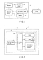
- FIG. 1 is a block diagram schematically showing a structural example of an IC card (a portable electronic device) 1 according to this embodiment and an IC card processing device 2 as an external device having a communicating function with respect to the IC card 1.
- the IC card processing device 2 has a terminal device 11, a display 12, a keyboard 13, a numeric keypad 14, a card reader/writer 15, and others.
- the terminal device 11 controls an entire operation of the IC card processing device.
- the terminal device 11 is constituted of a CPU, various kinds of memories, various kinds of interfaces, and others.
- the terminal device 11 is formed of a personal computer (PC).
- the terminal device 11 has a function of transmitting a command to the IC card 1 by using the card reader/writer 15, a function of performing various kinds of processing based on data received from the IC card 1, and others. For example, the terminal device 11 executes control of writing data in a data memory in the IC card 1 by transmitting a write command for data to the IC card 1 through the card reader/writer 15. Further, the terminal device 11 executes control of reading data from the data memory in the IC card 1 by transmitting a read command to the IC card 1.
- the display 12 is a display device that displays various kinds of information under control of the terminal device 11.
- the keyboard 13 functions as an operation unit operated by an operator of the IC card processing device 2, and the operator inputs various kinds of operation commands or data to the keyboard 13.
- the numeric keypad 14 functions as an input unit that is used to input information such as a user ID or a password.
- the card reader/writer 15 is an interface device that is used to communicate with the IC card 1.
- the card reader/writer 15 is formed of an interface conforming to a communication scheme of the IC card 1.
- the card reader/writer 15 is formed of, e.g., a contact unit that is used to be physically and electrically connected with a contact unit of the IC card 1.
- the card reader/writer 15 is formed of an antenna, a communication controller, and others that are used to achieve wireless communication with the IC card 1.
- power supply for the IC card 1 clock supply, reset control, and data transmission/reception are executed.
- Such functions enable the card reader/writer 15 to perform activation (boot) of the IC card 1, transmission of various kinds of commands, reception of a response for a transmitted command, and others based on control by the terminal device 11.
- the IC card 1 Upon receiving supply of power from a host device, e.g., the IC card processing device 2 through the card reader/writer 15, the IC card 1 is activated (becomes operable). For example, when the IC card 1 includes a contact type communicating function, i.e., when the IC card 1 is formed as a contact type IC card, the IC card 1 is activated by receiving supply of operation power and an operation clock from the card reader/writer 15 through a contact unit as a communication interface.
- a host device e.g., the IC card processing device 2 through the card reader/writer 15
- the IC card 1 is activated (becomes operable).
- the IC card 1 includes a contact type communicating function, i.e., when the IC card 1 is formed as a contact type IC card
- the IC card 1 is activated by receiving supply of operation power and an operation clock from the card reader/writer 15 through a contact unit as a communication interface.
- the IC card 1 when the IC card 1 includes a contactless type communicating function, i.e., when the IC card 1 is formed as a contactless type IC card, the IC card 1 receives an electric wave from the card reader/writer 15 through, e.g., an antenna and a modulation/demodulation circuit as a communication interface, and generates operation power and an operation clock from this electric wave by using a non-illustrated power supply unit, thereby being activated.
- a contactless type communicating function i.e., when the IC card 1 is formed as a contactless type IC card
- the IC card 1 receives an electric wave from the card reader/writer 15 through, e.g., an antenna and a modulation/demodulation circuit as a communication interface, and generates operation power and an operation clock from this electric wave by using a non-illustrated power supply unit, thereby being activated.
- FIG. 2 is a block diagram schematically showing a hardware structural example of the IC card 1 according to this embodiment.
- the IC card 1 has a built-in module M in a case constituting a main body B.
- the module M is integrally formed in a state where one or more IC chips C are connected with an external interface for communication (a communication unit).
- the module M is buried in the main body B of the IC card 1.
- the module M of the IC card 1 has a CPU (a control element) 21, a data memory 22, an RAM (a working memory) 23, an ROM (a program memory) 22, a communication unit 25, and others as shown in FIG. 2 .
- the control unit 21 controls the entire IC card 1.
- the control unit 21 operates based on a control program and control data stored in the program memory 24 or the data memory 22, thereby realizing various kinds of functions.
- the control unit 21 performs basic operation control over the IC card 1 by executing a program of an operating system.
- the control unit 21 carries out various kinds of operation controls associated with operation modes of the IC card by executing an application program meeting a utilization purpose of the IC card 1.
- the data memory 22 is a rewritable nonvolatile memory.
- the data memory 22 is formed of a data writable/rewritable nonvolatile memory such as an EEPROM (Electrically Erasable Programmable Read-Only Memory) or a flash ROM.
- a control program meeting an operation purpose of the IC card 1 or various kinds of data are written in the data memory 22.
- various kinds of files based on a standard of the IC card 1 are defined, and various kinds of data are written in these files. An example of a file stored in the data memory 22 will be described later.
- the RAM 23 is a volatile memory that functions as a working memory.
- the RAM 23 functions as a buffer that temporarily stores, e.g., data in processing.
- a management table a CURRENT pointer setting table 23a storing information indicative of an object that is in a current state in each record file.
- the ROM 24 is a non-volatile memory such as a mask ROM that functions as a program memory.
- the ROM 24 stores a control program or control data in advance.
- the ROM 24 is incorporated in the IC card 1 in a state where a control program or control data is stored on a manufacturing stage of the IC card.
- the control program or the control data stored in the ROM 24 controls a basic operation of the IC card and is incorporated in accordance with a specification of the IC card 1 in advance.
- the communication unit 25 is an interface that communicates with the IC card processing apparatus 2 through the reader/writer 15.
- the communication unit 25 is constituted of a communication control unit and a contact unit that physically and electrically come into contact with the reader/writer 15 to transmit or receive a signal.
- the communication unit 25 is constituted of, e.g., a communication control unit such as a modulation/demodulation circuit that wirelessly communicates with the reader/writer 15 and an antenna that is used to transmit/receive an electric wave.
- FIG. 3 is a view schematically showing a structural example of files stored in the data memory 22.
- FIG. 3 shows a file structural example in the portable electronic device such as an IC card.
- the example shown in FIG. 3 is a file structural example defined in ISO/IEC7816-4 as a standard concerning portable electronic devices such as an IC card.
- various kinds of files are managed in a tree structure.
- a plurality of fines having a hierarchy structure including an MF (Master File), a DF (Dedicated File), and an EF (Elementary File), and others.
- MF Master File
- DF DF
- DF 2 DF
- EF Electronic File
- the MF 31 is placed at the top in the file structure for various kinds of files stored in the data memory 22.
- the respective DFs (DF 1 and DF 2) 32 and 33 are provided in accordance with, e.g., applications. In this case, each of DFs 32 and 33 functions as a folder corresponding to each application.
- Each of EFs 34, 35, and 36 is a record file (a data file) storing actual data. That is, each EF 34, 35, or 36 provided under the DF 1 stores data that is used in an application associated with the DF 1. It is to be noted that the EF can be provided on the level immediately below the MF 31. Further, in the following description, it is assumed that the first EF 34 and the second EF 35 are binary record files each storing a plurality of data objects.
- FIGS. 4 and 5 are views showing a data structure of a record file in a memory region of the data memory 22.
- FIG. 4 shows a data structure of a first EF (EFID: 0001) 34.
- FIG. 5 shows a data structure of the second EF (EFID: 0002).
- the record file depicted in FIG. 4 or 5 is formed of a plurality of data objects.
- Each data object is constituted of an identifier (Tag), a data length (Length), and a data value (Value).
- the data object having such a data structure is called, e.g., a TLV object.
- the TLV object has a data structure in which data of the identifier "Tag", data of the data length "Length”, and data of the data value "Value" are sequentially coupled.
- An entire data size of such a TLV object can be judged based on a data size of the "data value” indicated by the "data length” if a data size of the "identifier” and a data size of the "data length” are determined. Therefore, the plurality of TLV objects can be continuously stored in a storage region of the record file.
- an identifier, a data length, and a data value of each data object are sequentially arranged from the top of a data region in the record file.
- FIGS. 4 and 5 shows a state where the plurality of TLV objects are stored in the record file.
- a storage region of an identifier of each data object is a region where a numerical value is surrounded by a rectangular.
- a storage region of a data length of each data object is a region where a numerical value is underlined.
- a storage region of a data value of each data object is a region where a numerical value having no rectangular and no underline given thereto is written (a region excluding identifiers and data lengths).
- one column at a left end in each of FIGS. 4 and 5 indicates an example of each address (a top address of each row) in the memory. It is to e noted that all numerical values depicted in FIGS. 4 and 5 are hexadecimal numbers.
- an identifier of a top TLV object (a first object) in this file is "01".
- a data length of this first object is "01". Therefore, "AA” as a data value of the first object is stored in a region corresponding to one byte following "01" as the data length of the first object.
- an identifier "02" of a subsequent TLV object (a second object) is stored to follow the data value "AA” of the first object, and a data length "03" of the second object is stored to follow the identifier "02".
- regions corresponding to 3 bytes following "03" as the data length of the second object "BB", “BB”, and "BB” as data values of the second object are stored.
- the data objects in the record file are managed by using a CURRENT pointer setting table 23a as a management table.
- the CURRENT pointer setting table 23a also corresponds to information indicative of a current state of a data object.
- the CURRENT pointer setting table 23a is provided in the RAM 23. Incidentally, it is good enough for the CURRENT pointer setting table 23a to be present in a storage region where data can be written or rewritten by the control unit 21.
- the CURRENT pointer setting table 23a may be provided in the data memory 22.
- the CURRENT pointer setting table 23a is generated and updated by the control unit 21.
- the control unit 21 generates the CURRENT pointer setting table 23a in regard to a record file selected as a current file.
- a specific record file is selected as a current file at the time of activation of the IC card 1 or based on a command from an external device, generating the CURRENT pointer setting table 23a can suffice.
- the data memory 22 may store the CURRENT pointer setting table 23a with respect to each record file. In this case, the control unit 21 appropriately updates the CURRENT pointer setting table 23a in accordance with each of various kinds of processing contents.
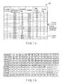
- FIG. 6 shows a structural example of the CURRENT pointer setting table 23a for the first EF (EFID: 0001) as a record file.
- the CURRENT pointer setting table 23a stores management information of all data objects in the first EF 34 depicted in FIG. 4 . That is, the CURRENT pointer setting table 23a depicted in FIG. 6 stores information such as file identification information (EFID), identifier (Tag) information, address (Address) information, data length (Length) information, and a current flag (a current pointer Flag) as management information of each data object in the first EF 34 shown in FIG. 4 .
- EFID file identification information
- Tag identifier
- Address address
- Length data length
- a current flag a current pointer Flag
- An EFID stored in the CURRENT pointer setting table 23a is information that is used to identify a record file storing each object.
- the example shown in FIG. 6 is a table that manages data objects in the first EF 34 depicted in FIG. 4 . Therefore, in the example depicted in FIG. 6 , an EFID of each data object is "0001".
- Identification information and data length information stored in the CURRENT pointer setting table 23a are an identifier and a data length of each data object. In the example shown in FIG. 6 , as the identifier information and the data length information of each data object, an identifier and a data length themselves of each data object stored in the first EF 34 depicted in FIG. 4 are stored.
- Address information stored in the CURRENT pointer setting table 23a is information indicative of a top address of each data objected in the data memory 22.
- the address information of each data object is discriminated sequentially from an identifier and a data length of each data object in the first EF 34 depicted in FIG. 4 .
- the current flag stored in the CURRENT pointer setting table 23a indicates whether a corresponding data object is in a current state. For example, the current flag of the data object that is in the current state is set to "1", and the current flag of the data object that is not in the current state is set to "0".
- FIG. 7 is a view showing a second structural example of the CURRENT pointer setting table 23a.
- FIG. 7 shows a structural example of the CURRENT pointer setting table 23a for the first EF 34 depicted in FIG. 4 and the second EF 35 shown in FIG. 5 .
- the CURRENT pointer setting table 23a in the second structural example holds information indicative of a current state in accordance with each logical channel.
- the CURRENT pointer setting table 23a stores management information of all data objects in the first EF 34 shown in FIG. 4 and the second EF 35 depicted in FIG. 5 .
- the first EF 34 is selected as a current file in a logical channel "0"
- the second EF 35 is selected as a current file in a logical channel "1”. That is, the CURRENT pointer setting table 23 shows a data object in the first EF 34 that is in the current state in the logical channel "0" and a data object in the second EF 35 that is in the current state in the logical channel "1".
- the logical channel generally means a logical channel in which the control unit 21 can execute various kinds of processing in the IC card 1.
- Each logical channel in the IC card is defined based on, e.g., ISO/IEC7816-4. That is, in the IC card 1, the control unit 21 can carry out various kinds of processing in parallel in accordance with each logical channel. In this case, the IC card 1 holds each processing content (e.g., current information) in each logical channel.
- a logical channel Ch. 0, Ch. 1, Ch. 2, and Ch. 3
- a default logical channel is "Ch. 0”
- the logical channel "Ch. 0" can be constantly utilized, and processing that open the logical channels (Ch. 1, Ch. 3, and Ch. 3) (make these channel available) in response to a command specifying a logical channel (e.g., a manage channel command) must be carried out.
- the CURRENT pointer setting table 23a depicted in FIG. 7 manages data objects in each record file in accordance with each logical channel as management information of each data object in the first EF 34 depicted in FIG. 4 and the second EF shown in FIG. 5 .
- the CURRENT pointer setting table 23a shown in FIG. 7 stores information, e.g., logical channel information, EFID information, identifier (Tag) information, address (Address) information, data length (Data Length) information, a current flag (a current pointer Flag), and others as management information of each data object.
- the logical channel information stored in the CURRENT pointer setting table 23a is information indicative of a logical channel in which a record file storing each data object is selected.
- the example depicted in FIG. 7 is a state where the first EF 34 shown in FIG. 4 is selected in the logical channel "0" and the second EF depicted in FIG. 5 is selected in the logical channel "1". Therefore, as shown in FIG. 7 , logical information associated with each data object having the EFID "0001" is "0" and logical channel information associated with each data object having the EFID "0002" is "1".
- Each identifier and each data length stored in the CURRENT pointer setting table 23a are an identifier and a data length themselves of each data object.
- an identifier and a data length of each data object stored in the first EF 34 depicted in FIG. 4 are stored as the identifier and the data length of each data object.
- Each address stored in the CURRENT pointer setting table 23a is information indicative of a top address of each data object in the data memory 22. The address information of each data object is specified sequentially from the identifier and the data length of each data object in the first EF 34 shown in FIG. 4 and the second EF 35 depicted in FIG. 5 .
- the current flag stored in the CURRENT pointer setting table 23a is indicative of whether a corresponding data object is in the current state in each logical channel.
- " 1 " is set to the current flag of each of an object that is in the current state in the logical channel "0" and a data object that is in the current state in the logical channel "1".
- FIG. 8 is a flowchart for explaining an example of creation processing for the CURRENT pointer setting table 23a.
- the IC card 1 is activated based on supply of the power from a host device, e.g., the IC card processing device 2 (a step S1). In this state, the IC card 1 can receive a command from the IC card processing device 2 (a step S2). When a command is received from the IC card processing device 2, the control unit 21 of the IC card 1 judges whether the received command is a command that specifies identification information (EFID) of a record file and an identifier (Tag) of a data object (a step S3).
- EFID identification information
- Tag identifier
- the control unit 21 judges whether the CURRENT pointer setting table 23a is present in the RAM 23 (a step S4). For example, it can be considered that the CURRENT pointer setting table 23a is not created in the RAM 23 immediately after activation of the IC card 1. Furthermore, when the CURRENT pointer setting table 23a is present, the control unit 21 omits the CURRENT pointer setting table creation processing.
- the control unit 21 creates the CURRENT pointer setting table 23a for the record file specified by the received command (a step S5).
- management information of each data object in the record file is extracted by sorting data in the record file specified by the received command. That is, the control unit 21 reads an identifier and a data length of each data object sequentially from the top of the record file. As a result, the control unit 21 sequentially discriminates a top address, an identifier, and a data length of each data object.
- the identifier and the data length of each data object is information itself read from the record file.
- the top address of each data object is discriminated based on, e.g., a data length of each data object with the top address of the record file being determined as a reference. That is, a top address of a first data object in the record file is the top address of the record file.
- Top addresses of second and subsequent data objects are discriminated based on data lengths of respective previous data objects. For example, the top address of the second or subsequent data object has an address value obtained by adding a size of an identifier and a size of a data length of an immediately preceding object and a size of a data value indicated by the data length to a top address of the immediately preceding data object.
- the control unit 21 When the management information of each data object in the record file specified by the received command is extracted, the control unit 21 stores the extracted management information of each data object in association with an EFID of the record file, thereby creating the CURRENT pointer setting table 23a. In this case, the control unit 21 sets the current flag in management information of a data object specified by the received command in the CURRENT pointer setting table 23a to be created. As a result, such a CURRENT pointer setting table 23a as depicted in FIG. 6 is created in the RAM 23.
- control unit 21 when executing processing in the plurality of logical channels, the control unit 21 creates such a CURRENT pointer setting table 23 associated with the plurality of logical channels as shown in FIG. 7 since the above-explained table is created in accordance with each record file selected in each logical channel.
- the control unit 21 executes processing requested by the received command (a step S6).
- the control unit 21 updates the CURRENT pointer setting table 23a in accordance with contents of the executed processing (a step S7). For example, when a data object that is in the current state is changed, the control unit 21 updates a state of the current flag in the CURRENT pointer setting table 23a.
- FIG. 9 is a flowchart for explaining processing for a command (a read command or a write command specifying CURRENT) that specifies a data object that is in the current state.
- the control unit 21 in the IC card 1 reads the CURRENT pointer setting table 23a associated with a corresponding record file. That is, the control unit 21 discriminates a logical channel of the received command. When the logical channel of the received command is discriminated, the control unit 21 specifies a data object that is in the current state in the logical channel of the received command from the CURRENT pointer setting table 23a (a step S12).
- the control unit 21 that has received the command with the logical channel "0" confirms a current flag of each data object with the logical channel "0" from the CURRENT pointer setting table 23a. That is, the control unit 21 retrieves a data object having the logical channel "0" and the current flag "1" from the CURRENT pointer setting table 23a.
- the data object having the logical channel "0" and the current flag "1" is a data object having an EFID "0001" and a tag "DF01". Therefore, the control unit 21 determines that the data object having the tag "DF01" in a record file having the EFID "0001" is in the current state.
- This data object having the EFID "0001" and the tag "DF01" determined to be in the current state is determined to have a top address "0059" based on the CURRENT pointer setting table 23a as shown in FIG. 7 .
- the control unit 21 can readily discriminate the top address of the data object that is in the current state by making reference to the CURRENT pointer setting table 23a in this manner. As a result, the control unit 21 can directly access the data object that is in the current state.
- the control unit 21 judges whether the received command is a read command or a write command (a step S13).
- the control unit 21 executes processing of writing data specified by the received command in a data region of the data object in the current state (update processing) (steps S14 to S16).
- the control unit 21 specifies a top address of the data object in the current state by using the CURRENT pointer setting table 23a.
- the control unit 21 initializes a region (a data region) of a data value (Value) stored to follow an identifier (Tag) and a data length (Length) from the top address of the data object that is in the current state (the step S14).
- the control unit 21 writes data specified by the received command in the initialized data region (the step S15).
- the control unit 21 generates response data including information indicative of a result of the write processing.
- the control unit 21 transmits the regenerated response data to the IC card processing device 2 as a transmission source of this received command (the step S16).
- the control unit 21 executes processing of reading data of the data object that is in the current state (steps S17 and S18).
- the control unit 21 specifies a top address of the data object in the current state by using the CURRENT pointer setting table 23a.
- control unit 21 reads a data value (Value) stored to follow an identifier (Tag) and a data length (Length) from the top address of the data object in the current state (the step S17).
- the control unit 21 When the data of the data object that is in the current state is read out, the control unit 21 generates a response data including the read data, and transmits the generated response data to the IC card processing device 2 as a transmission source of the received command (the step S18).
- FIG. 10 is a view showing an example of a result of processing based on the write command specifying CURRENT.
- FIG. 10 shows an example where a data object in the current state in the first EF 34 depicted in FIG. 4 is rewritten by making reference to the CURRENT pointer setting table 23a depicted in FIG. 7 .
- the IC card 1 that has received the write command specifying CURRENT rewrites the data object in the first EF 34 in FIG. 4 as shown in FIG. 10 .
- the control unit 21 updates the CURRENT pointer setting table 23a. For example, when a data length of a data object in the current state is changed due to, e.g., rewrite processing, a top address of each data object following the data object that is in the current state is also changed. In such a case, the control unit 21 discriminates the changed top address of each data object to update the CURRENT pointer setting table 23a.
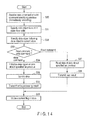
- FIG. 11 is a flowchart for explaining processing for a read command or a write command specifying NEXT.
- the IC card 1 has received a read command or a write command specifying NEXT from a host device, e.g., the IC card processing device 2 (a step S20).
- a host device e.g., the IC card processing device 2
- the control unit 21 in the IC card 1 discriminates a logical channel of the received command.
- the control unit 21 specifies a data object in the current state in the logical channel of the received command from the CURRENT pointer setting table 23a (a step S21).
- the control unit 21 further specifies a data object following the data object in the current state (a data object specified as NEXT) (a step S22).
- the control unit 21 that has received the command specifying NEXT with the logical channel "0" retrieves a data object having a logical channel "0" and a current flag "1" from the CURRENT pointer setting table 23a.
- the data object having the logical channel "0" and the current flag "1" (the data object in the current state) is a data object having an EFID "0001" and a tag "DF01".
- the data object following the data object in the current state is a data object having the EFID "0001” and a tag "DF02". Therefore, the control unit 21 determines that the data object having the EFID "0001" and the tag "DF01" as the data object specified as NEXT.
- the data object having the EFID "0001" and the tag "DF01" determined as the data object specified as NEXT is determined to have a top address "008C" by using the CURRENT pointer setting table 23a depicted in FIG. 7 .
- the control unit 21 can readily judge the top address of the data object specified as NEXT (the data object following the data object in the current state) by making reference to the CURRENT pointer setting table 23a in this manner. As a result, the control unit 21 can directly access the data object specified as NEXT.
- the control unit 21 judges whether the received command is a read command or a write command (a step S23).
- the control unit 21 executes processing of writing data specified by the received command in a data region of the data object specified as NEXT (update processing) (steps S24 to S26).
- the control unit 21 specifies a top address of the data object specified as NEXT by using the CURRENT pointer setting tale 23a.
- the control unit 21 initializes a region (a data region) of a data value (Value) stored to follow an identifier (Tag) and a data length (Length) from the top address of the data object specified as NEXT (the step S24).
- the control unit 21 writes data specified by the received command in the initialized data region (the step S25).
- the control unit 21 generates response data including information indicative of a result of the write processing.
- the control unit 21 transmits the generated response data to the IC card processing device 2 as a transmission source of the received command (the step S26).
- the control unit 21 executes processing of reading data of the data object specified as NEXT (steps S27 and S28).
- the control unit 21 specifies a top address of the data object specified as NEXT by using the CURRENT pointer setting table 23a.
- control unit 21 reads a data value (Value) stored to follow an identifier (Tag) and a data length (Length) from the top address of the data objected specified as NEXT (the step S27).
- the control unit 21 generates response data including the read data and transmits the generated data to the IC card processing device 2 as a transmission source of the received command (the step S28).
- a current state of the data object In the processing for the read command or the write command specifying NEXT, a current state of the data object must be changed.
- the data object specified as NEXT is changed to the current state. Therefore, the control unit 21 updates the current flag in the CURRENT pointer setting table 23a (a step S29). In this update processing, the current flag of the data object specified as NEXT is rewritten to "1", and the current flag of the data object in the current state is rewritten to "0".
- FIG. 12 shows a state of the CURRENT pointer setting table 23a after processing a command specifying NEXT.
- FIG. 12 depicts a state after processing a command specifying NEXT that is received when the CURRENT pointer setting table 23a is in the state shown in FIG. 7 . That is, when a command specifying NEXT is executed, a current state of a data object is changed to the next data object. This means that a data object whose current flag is set to "1" sequentially shifts in such a CURRENT pointer setting table 23a as depicted in FIG. 7 or 12 every time the command specifying NEXT is executed.
- FIG. 13 is a view showing an example of a result of processing based on the write command specifying NEXT. That is, FIG. 13 shows a result of processing of the write command specifying NEXT that is received when the CURRENT pointer setting table 23a is in the state shown in FIG. 7 .
- each data value (Value) of the data object having the identifier "DF02" is rewritten.
- This data object having the identifier "DF02" is a data object (a data object specified as NEXT) following the data object in the current state shown in the CURRENT pointer setting table 23a in FIG. 7 . That is, when the CURRENT pointer setting table 23a is in such a state as shown in FIG. 7 , the IC card 1 having received the write command specifying NEXT rewrites the data object in the first EF 34 in FIG. 4 as shown in FIG. 13 .
- control unit 21 likewise updates the CURRENT pointer setting table 23a when information other than the current flag in the CURRENT pointer setting table 23a is changed due to executed processing. For example, when a data length of a data object that is in the current state is changed due to, e.g., rewrite processing, a top address of each data object following the data object in the current state is also changed. In such a case, the control unit 21 discriminates the changed top address of each data object to update the CURRENT pointer setting table 23a.
- the data object in the current state shown in the CURRENT pointer setting table can be determined as a reference to sequentially read or write data in the data objects. For example, when a command specifying NEXT is continuously given, the IC card can efficiently execute processing of sequentially accessing the next data object by using the CURRENT pointer setting table with the data object in the current state being determined as a reference.
- FIG. 14 is a flowchart for explaining processing for a read command or a write command specifying PREVIOUS.
- the control unit 21 in the IC card 1 discriminates a logical channel of the received command.
- the control unit 21 specifies a data object in a current state in the logical channel of the received command from the CURRENT pointer setting table 23a (a step S31).
- the data object in the current state is discriminated based on whether its current flag is "1" in the CURRENT pointer setting table 23a.
- the control unit 21 specifies a data object (a data object specified as PREVIOUS) immediately before the data object in the current state (a step S32).
- the control unit 21 that has received the command specifying PREVIOUS in a logical channel "0" retrieves a data object having a logical channel "0" and a current flag "1" from the CURRENT pointer setting table 23a.
- the data object having the logical channel "0" and the current flag "1" (the data object in the current state) is a data object having an EFID "0001" and a tag "DF01".
- a data object immediately before the data object in the current state is a data object having an EFID "0001” and a tag "09". Therefore, the control unit 21 determines that the data object having the EFID "0001" and the tag "09” as a data object specified as PREVIOUS.
- That data object with the EFID "0001" and the tag "09" determined as the data object specified as PREVIOUS is determined to have a top address "0027" based on the CURRENT pointer setting table 23a depicted in FIG. 7 .
- the control unit 21 can readily discriminate the top address of the data object specified as PREVIOUS (the data object immediately preceding the data object in the current state) by making reference to the CURRENT pointer setting table 23a in this manner. As a result, the control unit 21 can directly access the data object specified as PREVIOUS.
- the control unit 21 judges whether the received command is a read command or a write command (a step S33).
- the control unit 21 executes processing of writing data specified by the received command in a data region of the data object specified as PREVIOUS (update processing) (steps S34 to S36).
- the control unit 21 specifies a top address of the data object specified as PREVIOUS by using the CURRENT pointer setting table 23a.
- control unit 21 initializes a region (a data region) of a data value (Value) stored to follow an identifier (Tag) and a data length (Length) from the top address of the data object specified as PREVIOUS (a step S34).
- the control unit 21 writes data specified by the received command in the initialized data region (a step S35).
- the control unit 21 generates response data including information indicative of a result of write processing.
- the control unit 21 transmits the generated response data to the IC card processing device 2 as a transmission source of the received command (a step S36).
- the control unit 21 executes processing of reading data of the data object specified as PREVIOUS (steps S37 and S38).
- the control unit 21 specifies a top address of the data object specified as PREVIOUS by using the CURRENT pointer setting table 23a.
- control unit 21 reads a data value (Value) stored to follow an identifier (Tag) and a data length (Length) from the top address of the data object specified as PREVIOUS (the step S37).
- the control unit 21 generates response data including the read data and transmits the generated data to the IC card processing device 2 as a transmission source of the received command.
- a current state of a data object In the processing for the read command or the write command specifying PREVIOUS, a current state of a data object must be changed. That is, the data object specified as PREVIOUS is changed to the current state. Therefore, the control unit 21 updates the current flag in the CURRENT pointer setting table 23a (a step S39). In this update processing, the current flag of the data object specified as PREVIOUS is rewritten to "1", and the current flag of the data object that is in the current state is rewritten to "0".
- FIG. 15 shows a state of the CURRENT pointer setting table 23a after processing a command specifying PREVIOUS.
- FIG. 15 depicts a state after processing a command specifying PREVIOUS received when the CURRENT pointer setting table 23a is in the state shown in FIG. 7 . That is, when a command specifying PREVIOUS is executed, a current state of a data object is changed to a subsequent data object. This means that a data object whose current flag is set to "1" sequentially shifts every time a command specifying PREVIOUS is executed in such a CURRENT pointer setting table 23a as shown in FIG. 7 or 15 .
- FIG. 16 is a view showing an example of a result of processing based on a write command specifying PREVIOUS.
- FIG. 16 shows an example of a result of processing for a write command specifying PREVIOUS received when the CURRENT pointer setting table 23a is in a state depicted in FIG. 7 .
- This data object having the identifier "09" is a data object (a data object specified as PREVIOUS) immediately preceding a data object in the current state shown in the CURRENT pointer setting table 23a depicted in FIG. 7 . That is, when the CURRENT pointer setting table 23a is in such a state as depicted in FIG. 7 , the IC card 1 having received a write command specifying PREVIOUS rewrites the data object in the first EF 34 in FIG. 4 as shown in FIG. 16 .
- control unit 21 likewise updates the CURRENT pointer setting table 23a when information other than the current flag in the CURRENT pointer setting table 23a varies due to executed processing. For example, when a data length of a data object specified as PREVIOUS is changed due to, e.g., rewrite processing, a top address of each data object following the data object specified as PREVIOUS is also changed. In such a case, the control unit 21 discriminates the changed top address of each data object to update the CURRENT pointer setting table.
- each data object immediately preceding a data object in the current state as a reference shown in the CURRENT pointer setting table can be sequentially read or written.
- the IC card can efficiently execute processing of sequentially accessing preceding data objects by using the CURRENT pointer setting table with a data object in the current state being determined as a reference.
Landscapes
- Engineering & Computer Science (AREA)
- Databases & Information Systems (AREA)
- Theoretical Computer Science (AREA)
- Data Mining & Analysis (AREA)
- Physics & Mathematics (AREA)
- General Engineering & Computer Science (AREA)
- General Physics & Mathematics (AREA)
- Software Systems (AREA)
- Information Retrieval, Db Structures And Fs Structures Therefor (AREA)
- Storage Device Security (AREA)
- Credit Cards Or The Like (AREA)
Applications Claiming Priority (1)
| Application Number | Priority Date | Filing Date | Title |
|---|---|---|---|
| JP2009056927A JP2010211516A (ja) | 2009-03-10 | 2009-03-10 | 携帯可能電子装置および携帯可能電子装置におけるアクセス制御方法 |
Publications (1)
| Publication Number | Publication Date |
|---|---|
| EP2228734A1 true EP2228734A1 (fr) | 2010-09-15 |
Family
ID=42246327
Family Applications (1)
| Application Number | Title | Priority Date | Filing Date |
|---|---|---|---|
| EP09155848A Withdrawn EP2228734A1 (fr) | 2009-03-10 | 2009-03-23 | Dispositif électronique portatif et procédé de contrôle d'accès d'un dispositif électronique portatif |
Country Status (4)
| Country | Link |
|---|---|
| US (1) | US20100235393A1 (fr) |
| EP (1) | EP2228734A1 (fr) |
| JP (1) | JP2010211516A (fr) |
| SG (1) | SG165200A1 (fr) |
Cited By (2)
| Publication number | Priority date | Publication date | Assignee | Title |
|---|---|---|---|---|
| EP2701110A1 (fr) * | 2012-08-23 | 2014-02-26 | Kabushiki Kaisha Toshiba | Carte à puce avec mémoire externe |
| CN104519359A (zh) * | 2013-09-29 | 2015-04-15 | 杭州海康威视数字技术股份有限公司 | 进行视频码流处理的设备及方法 |
Families Citing this family (2)
| Publication number | Priority date | Publication date | Assignee | Title |
|---|---|---|---|---|
| FR2983622B1 (fr) * | 2011-12-02 | 2014-01-24 | Morpho | Ecriture de donnees dans une memoire non volatile de carte a puce |
| JP6772545B2 (ja) * | 2016-05-19 | 2020-10-21 | 大日本印刷株式会社 | Icカード,tlvオブジェクトへのアクセス方法 |
Citations (4)
| Publication number | Priority date | Publication date | Assignee | Title |
|---|---|---|---|---|
| JP2008146343A (ja) * | 2006-12-08 | 2008-06-26 | Dainippon Printing Co Ltd | Icカード、および、更新プログラムの呼出し方法 |
| US20090050702A1 (en) | 2007-08-20 | 2009-02-26 | Kabushiki Kaisha Toshiba | Portable electronic device and control method of portable electronic device |
| JP2009075797A (ja) * | 2007-09-20 | 2009-04-09 | Toshiba Corp | 携帯可能電子装置 |
| EP2199994A1 (fr) * | 2008-12-19 | 2010-06-23 | Kabushiki Kaisha Toshiba | Dispositif électronique portable |
Family Cites Families (20)
| Publication number | Priority date | Publication date | Assignee | Title |
|---|---|---|---|---|
| JP2711216B2 (ja) * | 1993-01-26 | 1998-02-10 | インターナショナル・ビジネス・マシーンズ・コーポレイション | オブジェクトを管理するためのシステム及び方法 |
| US6484946B2 (en) * | 1997-12-22 | 2002-11-26 | Hitachi, Ltd. | IC card information display device and IC card for use therewith |
| WO2000076239A1 (fr) * | 1999-06-03 | 2000-12-14 | Nokia Mobile Phones Limited | Carte de circuit integre utilisee dans un terminal de communication |
| JP2001067210A (ja) * | 1999-08-30 | 2001-03-16 | Toshiba Corp | Icカードとicカードにおけるアプリケーションのインストール方法 |
| US7024532B2 (en) * | 2001-08-09 | 2006-04-04 | Matsushita Electric Industrial Co., Ltd. | File management method, and memory card and terminal apparatus that make use of the method |
| AUPR966001A0 (en) * | 2001-12-20 | 2002-01-24 | Canon Information Systems Research Australia Pty Ltd | A microprocessor card defining a custom user interface |
| EP1363469A1 (fr) * | 2002-05-15 | 2003-11-19 | Siemens Aktiengesellschaft | Méthode d'affectation de priorité aux objects représentant les paramètres de connexion dans un service de messagerie multi-média (MMS) |
| JP4428055B2 (ja) * | 2004-01-06 | 2010-03-10 | ソニー株式会社 | データ通信装置及びデータ通信装置のメモリ管理方法 |
| US7343452B2 (en) * | 2004-03-31 | 2008-03-11 | Kabushiki Kaisha Toshiba | Apparatus for direct access to only specific lower hierarchy data in a nest structure |
| TWI258077B (en) * | 2004-05-11 | 2006-07-11 | Winbond Electronics Corp | Method of DMA and program DMA controller for card reader |
| JP2005332221A (ja) * | 2004-05-20 | 2005-12-02 | Renesas Technology Corp | 記憶装置 |
| KR101051703B1 (ko) * | 2004-08-09 | 2011-07-25 | 삼성전자주식회사 | 서스펜드/리쥼 기능을 갖는 집적 회로 카드 및 집적 회로카드 시스템 |
| JP4655545B2 (ja) * | 2004-08-23 | 2011-03-23 | ソニー株式会社 | メモリーカード及び再生装置 |
| US7428992B2 (en) * | 2005-01-11 | 2008-09-30 | Matsushita Electric Industrial Co., Ltd. | Secure device and system for issuing IC cards |
| JP4825431B2 (ja) * | 2005-03-08 | 2011-11-30 | パナソニック株式会社 | アクセスコントロール装置 |
| US7457934B2 (en) * | 2006-03-22 | 2008-11-25 | Hitachi, Ltd. | Method and apparatus for reducing the amount of data in a storage system |
| JP4787055B2 (ja) * | 2006-04-12 | 2011-10-05 | 富士通株式会社 | 情報分割記録機能を持つ情報処理装置 |
| FR2908202B1 (fr) * | 2006-11-07 | 2009-03-13 | Oberthur Card Syst Sa | Procede et dispositif de personnalisation d'une entite electronique portable |
| JP2008139923A (ja) * | 2006-11-30 | 2008-06-19 | Dainippon Printing Co Ltd | 共有オブジェクトを有するicカード、共有オブジェクトへのアクセス管理方法、及び、icカードプログラム |
| JP5313600B2 (ja) * | 2008-09-16 | 2013-10-09 | 株式会社日立製作所 | ストレージシステム、及びストレージシステムの運用方法 |
-
2009
- 2009-03-10 JP JP2009056927A patent/JP2010211516A/ja not_active Withdrawn
- 2009-03-23 US US12/408,965 patent/US20100235393A1/en not_active Abandoned
- 2009-03-23 EP EP09155848A patent/EP2228734A1/fr not_active Withdrawn
- 2009-03-23 SG SG200902034-8A patent/SG165200A1/en unknown
Patent Citations (4)
| Publication number | Priority date | Publication date | Assignee | Title |
|---|---|---|---|---|
| JP2008146343A (ja) * | 2006-12-08 | 2008-06-26 | Dainippon Printing Co Ltd | Icカード、および、更新プログラムの呼出し方法 |
| US20090050702A1 (en) | 2007-08-20 | 2009-02-26 | Kabushiki Kaisha Toshiba | Portable electronic device and control method of portable electronic device |
| JP2009075797A (ja) * | 2007-09-20 | 2009-04-09 | Toshiba Corp | 携帯可能電子装置 |
| EP2199994A1 (fr) * | 2008-12-19 | 2010-06-23 | Kabushiki Kaisha Toshiba | Dispositif électronique portable |
Cited By (4)
| Publication number | Priority date | Publication date | Assignee | Title |
|---|---|---|---|---|
| EP2701110A1 (fr) * | 2012-08-23 | 2014-02-26 | Kabushiki Kaisha Toshiba | Carte à puce avec mémoire externe |
| US9779347B2 (en) | 2012-08-23 | 2017-10-03 | Kabushiki Kaisha Toshiba | Smart card and portable electronic apparatus |
| CN104519359A (zh) * | 2013-09-29 | 2015-04-15 | 杭州海康威视数字技术股份有限公司 | 进行视频码流处理的设备及方法 |
| CN104519359B (zh) * | 2013-09-29 | 2017-09-22 | 杭州海康威视数字技术股份有限公司 | 进行视频码流处理的设备及方法 |
Also Published As
| Publication number | Publication date |
|---|---|
| JP2010211516A (ja) | 2010-09-24 |
| US20100235393A1 (en) | 2010-09-16 |
| SG165200A1 (en) | 2010-10-28 |
Similar Documents
| Publication | Publication Date | Title |
|---|---|---|
| EP2169639A1 (fr) | Dispositif électronique portatif et procédé de traitement de données dans un dispositif électronique portable | |
| US9183400B2 (en) | IC card and IC card control method | |
| EP2216719A1 (fr) | Appareil électronique mobile et procédé de gestion des données dans un appareil électronique mobile | |
| US8645624B2 (en) | Portable electronic device, smartcard and control method for portable electronic device | |
| SG179374A1 (en) | Ic card, mobile electronic device and data processing method in ic card | |
| EP2228734A1 (fr) | Dispositif électronique portatif et procédé de contrôle d'accès d'un dispositif électronique portatif | |
| US8082395B2 (en) | Portable electronic device | |
| CN101976211B (zh) | 一种在cap文件中替换函数的方法、装置及系统 | |
| JP6833364B2 (ja) | Icカード、および、icカード処理装置 | |
| EP2367115A1 (fr) | Appareil électronique portable et procédé de contrôle d'un appareil électronique portable | |
| KR100746036B1 (ko) | 플래시 메모리를 제어하는 장치 및 방법 | |
| JP2012208910A (ja) | 携帯可能電子装置、及び携帯可能電子装置の処理システム | |
| JP6769150B2 (ja) | 電子情報記憶媒体、情報処理方法、及び情報処理プログラム | |
| JP5971687B2 (ja) | Icカード、携帯可能電子装置及びicカードのコマンド処理方法 | |
| JP5214291B2 (ja) | Icカードおよびicカードの制御方法 | |
| JP2012133656A (ja) | 携帯可能電子装置及びicカード | |
| JP5932588B2 (ja) | Icカード、携帯可能電子装置、及びicカード処理装置 | |
| JP5038918B2 (ja) | 携帯可能電子装置および携帯可能電子装置の制御方法 | |
| US20090083273A1 (en) | Portable electronic apparatus and control method for portable electronic apparatus | |
| JP2010218147A (ja) | 携帯可能電子装置および携帯可能電子装置におけるメモリ制御方法 | |
| JP2018194995A (ja) | 電子情報記憶媒体、icカード、データ送信方法、データ書き込み方法、データ送信プログラム及びデータ書き込みプログラム | |
| JP2026054830A (ja) | 電子情報記憶媒体、icチップ、icカード、端末装置、データ書き換え方法、データ送信方法、媒体用プログラム、及び端末用プログラム | |
| KR20040034782A (ko) | 스마트 카드를 이용한 단말기 시스템 업그레이드 방법 및그 장치 | |
| JP6039036B2 (ja) | Icカード、携帯可能電子装置及びicカードの制御方法 | |
| JP2009176034A (ja) | 携帯可能電子装置、及び、データ管理方法 |
Legal Events
| Date | Code | Title | Description |
|---|---|---|---|
| PUAI | Public reference made under article 153(3) epc to a published international application that has entered the european phase |
Free format text: ORIGINAL CODE: 0009012 |
|
| 17P | Request for examination filed |
Effective date: 20090323 |
|
| AK | Designated contracting states |
Kind code of ref document: A1 Designated state(s): AT BE BG CH CY CZ DE DK EE ES FI FR GB GR HR HU IE IS IT LI LT LU LV MC MK MT NL NO PL PT RO SE SI SK TR |
|
| AX | Request for extension of the european patent |
Extension state: AL BA RS |
|
| AKX | Designation fees paid |
Designated state(s): FR |
|
| REG | Reference to a national code |
Ref country code: DE Ref legal event code: R108 Effective date: 20110419 |
|
| STAA | Information on the status of an ep patent application or granted ep patent |
Free format text: STATUS: THE APPLICATION HAS BEEN WITHDRAWN |
|
| 18W | Application withdrawn |
Effective date: 20151026 |