EP2229103B1 - Procédé et système de compensation du gain de contrainte en imagerie d'élasticité - Google Patents
Procédé et système de compensation du gain de contrainte en imagerie d'élasticité Download PDFInfo
- Publication number
- EP2229103B1 EP2229103B1 EP20080861395 EP08861395A EP2229103B1 EP 2229103 B1 EP2229103 B1 EP 2229103B1 EP 20080861395 EP20080861395 EP 20080861395 EP 08861395 A EP08861395 A EP 08861395A EP 2229103 B1 EP2229103 B1 EP 2229103B1
- Authority
- EP
- European Patent Office
- Prior art keywords
- strain
- compensation function
- strain compensation
- physiology
- image
- Prior art date
- Legal status (The legal status is an assumption and is not a legal conclusion. Google has not performed a legal analysis and makes no representation as to the accuracy of the status listed.)
- Not-in-force
Links
- 238000000034 method Methods 0.000 title claims description 63
- 238000003384 imaging method Methods 0.000 title claims description 38
- 230000035479 physiological effects, processes and functions Effects 0.000 claims description 24
- 239000000523 sample Substances 0.000 claims description 11
- 238000012285 ultrasound imaging Methods 0.000 claims description 10
- 238000002592 echocardiography Methods 0.000 claims description 7
- 238000012545 processing Methods 0.000 claims description 6
- 238000003860 storage Methods 0.000 claims description 6
- 238000003825 pressing Methods 0.000 claims description 3
- 230000008569 process Effects 0.000 claims description 3
- 238000013178 mathematical model Methods 0.000 claims 1
- 230000006870 function Effects 0.000 description 60
- 210000001519 tissue Anatomy 0.000 description 49
- 238000004590 computer program Methods 0.000 description 5
- 230000033001 locomotion Effects 0.000 description 5
- 230000003902 lesion Effects 0.000 description 4
- 238000005259 measurement Methods 0.000 description 4
- 238000002604 ultrasonography Methods 0.000 description 4
- 230000002159 abnormal effect Effects 0.000 description 3
- 230000005540 biological transmission Effects 0.000 description 3
- 230000006835 compression Effects 0.000 description 3
- 238000007906 compression Methods 0.000 description 3
- 230000000694 effects Effects 0.000 description 3
- 230000004044 response Effects 0.000 description 3
- 238000013481 data capture Methods 0.000 description 2
- 238000006073 displacement reaction Methods 0.000 description 2
- 238000009826 distribution Methods 0.000 description 2
- 230000005284 excitation Effects 0.000 description 2
- 230000001939 inductive effect Effects 0.000 description 2
- 239000000463 material Substances 0.000 description 2
- 238000012986 modification Methods 0.000 description 2
- 230000004048 modification Effects 0.000 description 2
- 210000000056 organ Anatomy 0.000 description 2
- 230000000241 respiratory effect Effects 0.000 description 2
- 230000003213 activating effect Effects 0.000 description 1
- 230000006978 adaptation Effects 0.000 description 1
- 230000003044 adaptive effect Effects 0.000 description 1
- 238000013459 approach Methods 0.000 description 1
- 230000010351 cardiac pulsation Effects 0.000 description 1
- 238000006243 chemical reaction Methods 0.000 description 1
- 238000007405 data analysis Methods 0.000 description 1
- 230000001419 dependent effect Effects 0.000 description 1
- 238000001514 detection method Methods 0.000 description 1
- 238000002059 diagnostic imaging Methods 0.000 description 1
- 238000009499 grossing Methods 0.000 description 1
- 230000010365 information processing Effects 0.000 description 1
- 210000004185 liver Anatomy 0.000 description 1
- 239000011159 matrix material Substances 0.000 description 1
- 238000005457 optimization Methods 0.000 description 1
- 238000002559 palpation Methods 0.000 description 1
- 230000002688 persistence Effects 0.000 description 1
- 230000010349 pulsation Effects 0.000 description 1
- 230000005855 radiation Effects 0.000 description 1
- 210000004872 soft tissue Anatomy 0.000 description 1
- 230000003068 static effect Effects 0.000 description 1
- 238000006467 substitution reaction Methods 0.000 description 1
- 230000002123 temporal effect Effects 0.000 description 1
Images




Classifications
-
- A—HUMAN NECESSITIES
- A61—MEDICAL OR VETERINARY SCIENCE; HYGIENE
- A61B—DIAGNOSIS; SURGERY; IDENTIFICATION
- A61B8/00—Diagnosis using ultrasonic, sonic or infrasonic waves
- A61B8/08—Clinical applications
-
- A—HUMAN NECESSITIES
- A61—MEDICAL OR VETERINARY SCIENCE; HYGIENE
- A61B—DIAGNOSIS; SURGERY; IDENTIFICATION
- A61B5/00—Measuring for diagnostic purposes; Identification of persons
- A61B5/0048—Detecting, measuring or recording by applying mechanical forces or stimuli
- A61B5/0053—Detecting, measuring or recording by applying mechanical forces or stimuli by applying pressure, e.g. compression, indentation, palpation, grasping, gauging
-
- A—HUMAN NECESSITIES
- A61—MEDICAL OR VETERINARY SCIENCE; HYGIENE
- A61B—DIAGNOSIS; SURGERY; IDENTIFICATION
- A61B8/00—Diagnosis using ultrasonic, sonic or infrasonic waves
- A61B8/48—Diagnostic techniques
- A61B8/485—Diagnostic techniques involving measuring strain or elastic properties
-
- A—HUMAN NECESSITIES
- A61—MEDICAL OR VETERINARY SCIENCE; HYGIENE
- A61B—DIAGNOSIS; SURGERY; IDENTIFICATION
- A61B8/00—Diagnosis using ultrasonic, sonic or infrasonic waves
- A61B8/46—Ultrasonic, sonic or infrasonic diagnostic devices with special arrangements for interfacing with the operator or the patient
- A61B8/461—Displaying means of special interest
-
- A—HUMAN NECESSITIES
- A61—MEDICAL OR VETERINARY SCIENCE; HYGIENE
- A61B—DIAGNOSIS; SURGERY; IDENTIFICATION
- A61B8/00—Diagnosis using ultrasonic, sonic or infrasonic waves
- A61B8/46—Ultrasonic, sonic or infrasonic diagnostic devices with special arrangements for interfacing with the operator or the patient
- A61B8/467—Ultrasonic, sonic or infrasonic diagnostic devices with special arrangements for interfacing with the operator or the patient characterised by special input means
Definitions
- This disclosure relates generally to imaging systems and more specifically to a method and system for elasticity imaging.
- Elasticity imaging consists of inducing motion in a biological tissue and evaluating the response of the tissue using diagnostic imaging techniques.
- Elasticity imaging can be used to reveal the mechanical properties of the tissue, such as Poisson's Ratio, Young's Modulus or other stiffness measurements.
- the measurements can provide an array of data in which array locations correspond to tissue locations in an image plane.
- the array of data may be mapped to a gray scale or a color map to form a picture.
- Elasticity imaging can include capturing the data during externally or internally applied tissue motion or deformation; evaluating tissue response, and presenting an image representative of the tissue property.
- Elasticity imaging techniques can be categorized into two groups based on tissue excitation techniques. Static methods use quasistatic compression and estimate resulting tissue strain. Stiff tissue shows less strain than softer tissue under applied force. Thus, by estimating tissue strain induced by compression, tissue stiffness information can be obtained. The estimated strain can also be used for reconstruction of the tissue elasticity modulus.
- the other category is based on inducing a dynamic excitation in tissue (dynamic method). In sonoelasticity, low frequency vibration ( ⁇ 1 kHz) is applied to tissues, and the tissue response is inspected. Another approach in this category is acoustic remote palpation where acoustic radiation force is applied in a local tissue area, and the resulting displacement is estimated.
- the ultrasound data before and after the compression is recorded to determine axial and lateral motions using correlation methods.
- the determined motions along the ultrasound propagation direction represent the axial displacement map of the tissue and are used to determine the axial strain map.
- the strain map is then displayed as a gray scale or color-coded image and is called an elastogram.
- US 2006/0025682 A1 discloses a method and apparatus for providing improved ultrasonic strain measurements of soft tissue. Rather than deducing tissue strain by measuring motion of the tissue under assumptions about stress fields and acoustic properties, strain is therein deduced directly from the modification of the ultrasonic signal caused by changes in the acoustic properties of the material.
- the applied stress during elasticity imaging can be non-uniform within the image plane. This can result in a strain image with variable appearance over the field of view even for tissue with uniform stiffness.
- the strain image can vary with depth in uniform tissue due to stress decay over depth. This can mislead users to perceive that the strain variation is due to a variation in tissue stiffness.
- a method of elasticity imaging according to claim 1 is provided.
- the method can include transmitting ultrasonic energy and receiving echoes therefrom; processing imaging data from the echoes associated with an applied stress of a physiology of a patient; obtaining a strain compensation function associated with the applied stress; applying the strain compensation function to the imaging data to generate a compensated strain image; and presenting the compensated strain image.
- the method furthermore comprises the step of adjusting the strain compensation function based on user inputs, wherein the user inputs are based on expected results associated with a portion of the physiology.
- a computer readable storage medium in which computer-executable code is stored, is provided.
- the computer-executable code is configured to cause a computing device in which the computer-readable storage medium is loaded to execute the steps of the above mentioned method.
- an ultrasound imaging system can have a probe for transmitting ultrasonic energy into a physiology of a patient and receiving echoes, a display device, and a processor operably coupled to the probe and the display device.
- the processor can process ultrasound imaging data associated with an applied stress of the physiology of the patient.
- the processor can generate a strain compensation function associated with the applied stress based on at least one of (i) user inputs based on expected results associated with a portion of the physiology, (ii) a strain compensation model generated prior to processing the ultrasound imaging data, and (iii) at least a portion of the processed imaging data.
- the processor can apply the strain compensation function to the imaging data to generate a compensated strain image.
- the processor can present on the display device at least one of the compensated strain image and an inverse of the compensated strain image.
- the system further comprises a compensation function control adapted to be actuated by a user such that the magnitude of the strain compensation function is adjusted based on results expected by the user and associated with the portion of the physiology.
- the technical effect includes, but is not limited to, presenting images that qualitatively highlight elastic differences in the physiology of a body.
- the technical effect further includes, but is not limited to, presenting images that highlight differences between normal tissue and lesions.
- the technical effect yet further includes, but is not limited to, presenting images that highlight localized areas of abnormal strain.
- the exemplary embodiments of the present disclosure are described with respect to data capture and imaging of a body performed by an ultrasound imaging device based on strain being examined with respect to a physiology of the body. It should be understood by one of ordinary skill in the art that the exemplary embodiments of the present disclosure can be applied to various portions of the body and various physiology, whether human or animal, such as tissue, organs, and so forth, including the liver.
- the applied stress resulting in the examined strain of the present disclosure can be external or internal to the body.
- the source of the applied stress can vary, such as generated from pressing down with the transducer, generated by a separate device, generated by application of wave propagation through the tissue, or created by the body itself, including arterial pulsations or respiratory variations in the patient.
- the amount and/or timing of the applied stress can also vary, including periodically applied stress that is qualitatively examined according to the exemplary embodiments of the present disclosure.
- the exemplary embodiments of the present disclosure can provide a more uniform strain image, such as for homogeneous tissue over a field of view, or a portion thereof, of the ultrasound system, and can highlight various physiological differences, such as between normal tissue and lesions.
- an elastographic image can be generated by normalizing the strain image with a modified or estimated stress.
- the modified or estimated stress can be user-generated and/or system-generated as will be described later.
- a modification or estimate of the stress can be generated, SC(X,Y), for the applied stress.
- the modified stress, SC(X,Y) can then be used to generate an estimate of the elastic modulus distribution as follows: 1 / Elasticity Modulus X Y ⁇ Strain X Y / SC X Y or, equivalently: Elasticity Modulus X Y ⁇ SC X Y / Strain X Y
- a compensated strain image generated according to an exemplary embodiment of the present disclosure can provide normal tissue with a more uniform appearance than an uncompensated strain image, helping to highlight localized areas of abnormal strain.
- the qualitative results provided by the compensated strain image of the present disclosure can be applicable even where the modified stress SC(X,Y) deviates significantly from the actual stress distribution in tissue.
- an ultrasound imaging system in accordance with one exemplary embodiment of the invention is shown and generally represented by reference numeral 10.
- the system 10 can perform ultrasound imaging on a patient's body 50, such as of an organ or tissue 150, and can include a processor or other control device 100, a probe or transducer 120, and a display device 170.
- the system 10 can include a stress device 125 for generating and applying the stress to the body 50.
- the stress device 125 can be an externally and/or internally used device, and can provide the applied stress to the region of interest in a number of different ways, including energy wave propagation or mechanically generated forces.
- the processor 100 can include various components for performing ultrasound imaging, and can employ various imaging techniques, such as with respect to data capture, analysis and presentation.
- the processor 100 can include a strain function control or actuator 205 to adjust the strain compensation function, as will be described later.
- the processor 100 can also include a time-gain compensation control or actuator 210, and a lateral-gain compensation control or actuator 215, as well as other ultrasound components, such as a transmitter/receiver, a beamformer, an echo processor, and a video processor.
- the present disclosure also contemplates one or more of these components being combined.
- the ultrasonic probe 120 can include a linear array of ultrasonic transducer elements 225 which transmit and receive the ultrasonic energy, such as under the control of the beamformer.
- the beamformer can control the timing of actuation of the transducer array elements 225 by activating transducer pulsers of the transmitter/receiver at appropriate times.
- the probe 120 can be a matrix array transducer that provides a steered and focused ultrasonic beam.
- the display device 170 can then be used to present the image generated by the processor 100.
- Various other components and techniques can be utilized by system 10 for generating, transmitting and receiving ultrasonic energy, as well as for processing the received ultrasonic energy.
- the components and techniques of system 10 allow for presentation of a strain image in 2D or 3D on the display device 170 of a region of interest of the body 50.
- the system 10 can also include a memory device, such as a CINELOOP® memory.
- the memory device can store data processed by the system 10 to form a first strain image or image stream so that subsequent strain images or image streams can be generated therefrom.
- processor 100 can also be used with the processor 100, such as an automatic border detection processor that can define and graphically overlay anatomical borders with respect to the images presented.
- an automatic border detection processor that can define and graphically overlay anatomical borders with respect to the images presented.
- present disclosure also contemplates the use of other components and/or techniques in addition to, or in place of, the components of system 10 described above.
- FIG. 3 an exemplary method of operation of the system 10 is shown and generally represented by reference numeral 300. It would be apparent to one of ordinary skill in the art that other embodiments not depicted in FIG. 3 are possible without departing from the scope of the claims described below, including examination of other portions of the body.
- Method 300 can begin with step 302 in which imaging data is captured by system 10, such as through the transmission and reception of ultrasonic energy or pulses by the probe 120 in combination with an applied stress in a region of interest.
- the applied stress can be provided by a number of sources, including applying pressure at the skin level of the body using the transducer probe 120 or as created by the body itself, such as cardiac pulsations or respiratory variations.
- the strain resulting from the applied stress can be determined from the data that was captured.
- the system 10 can monitor for user input of an adjustment to the strain compensation function by a clinician or other user, such as through rotation or other adjustment of the strain compensation function control 205. If an adjustment to the strain compensation function is detected then a strain compensation function can be generated or otherwise adjusted as in step 308. In one embodiment, the strain compensation function can initially be set at unity so that the strain image is initially presented as an uncompensated strain image.
- the adjustment to the strain compensation function can be to a magnitude of the strain compensation function as a function of depth.
- the present disclosure also contemplates the adjustment to the strain compensation function being a function of lateral and/or elevation positions.
- a clinician or other user can adjust the strain compensation function based on expected results, such as by adjustment until tissues or other physiology with expected uniform properties appear substantially uniform on the presented image.
- the adjustment to the strain compensation function can be based on the clinician's or other user's subjective view of the real-time image or image stream and known physiology in a localized area of the image so that a qualitative image can be presented with respect to other areas of the image that do not have uniform properties.
- the present disclosure contemplates the adjustment to the strain compensation function being performed at various times.
- the adjustment can be in real-time as described above or the data captured can be presented in a loop and the clinician can make the adjustment during the loop presentation, such as during or shortly after the patient's examination.
- the strain compensation function can be applied to the determined strain data or any subsequent determination of the strain, as in step 310.
- a compensated strain image can be presented, such as on display device 170.
- an elastogram or other print-out can be presented, such as of other data generated based on the compensated strain image.
- FIGS. 1-2 and 4 an exemplary method of operation of the system 10 is shown and generally represented by reference numeral 400. It would be apparent to one of ordinary skill in the art that other embodiments not depicted in FIG. 4 are possible without departing from the scope of the claims described below, including examination of other portions of the body. For example, possible variants to method 400 are shown in broken lines.
- Method 400 can begin with step 402 in which imaging data is captured by system 10, such as through the transmission and reception of ultrasonic energy or pulses by the probe 120 in combination with an applied stress in a region of interest.
- step 404 the strain resulting from the applied stress can be determined from the data that was captured or otherwise retrieved.
- a strain compensation function model can be obtained and applied to the captured data.
- the strain compensation function model can be generated or otherwise obtained using a number of techniques.
- the strain compensation function model can be modeled mathematically, set empirically during optimization with the same or other patients using physiology with known properties, and/or measured on a uniform tissue-mimicking phantom or other physical model for the particular physiology to be imaged.
- the strain compensation function model may then be stored and applied to subsequent imaging examinations for the same or different patients.
- the choice of which model to apply can be based on a number of factors, such as the type of physiology being examined, the age of the patient, and so forth.
- a strain compensation function can be generated or otherwise adjusted based on the a priori strain compensation function model, as in step 408.
- the strain compensation function can initially be set at unity so that the strain image is initially presented as an uncompensated strain image.
- the system 10 in step 409 can monitor for an adjustment to the strain compensation function by a clinician or other user, such as through rotation or other adjustment of the strain compensation function control 205. If an adjustment to the strain compensation function is detected then the strain compensation function determined from the a priori model can be adjusted accordingly.
- the strain compensation function can be applied to the determined strain data or any subsequent determination of the strain, as in step 410.
- a compensated strain image can be presented, such as on display device 170.
- an elastogram or other print-out can be presented, such as of other data generated based on the compensated strain image.
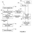
- FIGS. 1-2 and 5 an exemplary method of operation of the system 10 is shown and generally represented by reference numeral 500. It would be apparent to an artisan with ordinary skill in the art that other embodiments not depicted in FIG. 5 are possible without departing from the scope of the claims described below, including examination of other portions of the body. For examples, possible variants to method 500 are shown in broken lines.
- Method 500 can begin with step 502 in which imaging data is captured by system 10, such as through the transmission and reception of ultrasonic energy or pulses by the probe 120 in combination with an applied stress in a region of interest.
- step 504 the strain resulting from the applied stress can be determined from the data that was captured or otherwise retrieved.
- the captured data can be used to generate a strain compensation function.
- the strain compensation function can be generated based on a median strain calculated as a function of depth. Setting the strain compensation function based on the median strain as a function of depth yields a normalized strain function.
- the generated curve representative of the strain compensation function can be smoothed in step 507 so that there are no abrupt direction changes.
- either or both of user input in step 508 or an a priori model as in step 509 can also be used in generating or otherwise adjusting the strain compensation function.
- the strain compensation function can be applied to the determined strain data or any subsequent determination of the strain, as in step 510.
- a compensated strain image can be presented, such as on display device 170, including in real-time or in a stream loop.
- an elastogram or other print-out can be presented, such as of other data generated based on the compensated strain image.
- the method 500 contemplates other techniques and algorithms being utilized to generate a strain compensation function from the captured data, including lateral-gain compensation techniques.
- two or more of the techniques described above with respect to methods 300, 400 and 500 can be applied to generate a compensated strain image.
- an uncompensated strain image which has a hard inclusion, with an elastic modulus of approximately three times the surrounding tissue, in a substantially uniform background tissue.
- the applied stress was generated by pushing a linear array transducer in the depth direction in a tissue mimicking phantom or model, but the results are applicable to application on actual tissue.
- the strain varies with depth due to depth-dependent variation in the applied stress.
- FIG. 7 the mathematical inverse of the uncompensated strain image of FIG. 6 is shown and again indicates large variations of strain, even in regions of the similar tissue properties.
- FIG. 8 an image representative of a strain compensation function that can be generated by system 10 based upon median strain as a function of depth is shown.
- FIG. 9 a compensated strain image generated by system 10 based upon the strain compensation function of FIG. 8 is shown.
- the tissue which has uniform properties and is surrounding the hard inclusion appears more uniform, drawing attention to the inclusion.
- the inclusion appears 2 to 3 times stiffer than the surrounding tissue in the image, where the actual stiffness is three times the surrounding tissue.
- FIG. 10 shows the mathematical inverse of the compensated strain image of FIG. 9 .
- the tissue surrounding the hard inclusion appears at a more uniform level, providing better contrast with the inclusion.
- FIG. 11 an image representative of another exemplary strain compensation function that can be generated by system 10 which varies both axially and laterally, so as to be 2-Dimensional, is shown.
- FIG. 12 a compensated strain image generated by system 10 based upon the strain compensation function of FIG. 11 is shown.
- System 10 can provide for qualitative imaging of strain based on a number of techniques including a user control to compensate strain as a function of depth, lateral and/or elevation positions; compensation of strain as a function of depth based upon predetermined compensation functions stored on the system; and/or adaptive compensation of strain images to account for non-uniform applied stress over a 2D or 3D field of view using the data captured during the examination.
- the methodology and system described herein is applicable to compensated strain images in either or both of 2D and 3D imaging.
- Elastograms can include not only strain images but also other measurements related to tissue elasticity (e.g., ratio of lesion/normal tissues strain, Poisson's Ratio). Compensated strain images generated in accordance with the systems and methods of the present disclosure may not be directly displayed to users and can be further processed to produce elastograms.
- the present disclosure contemplates the strain compensation function being based upon one or more of the following sources: user input (via controls); a priori data/model; current and past values of strain data.
- the methods of the exemplary embodiments can include presenting the strain data for display (image and/or graphical) and/or storage /export.
- further processing of the data can be performed, including smoothing, remapping, (e.g., 1/compensated strain, Fn(compensated strain), and so forth), temporal persistence and any combination thereof.
- the imaging performed herein can include other techniques for either of both of 2-dimensional and 3-dimensional image data.
- the invention can be realized in hardware, software, or a combination of hardware and software.
- the invention can be realized in a centralized fashion in one computer system, or in a distributed fashion where different elements are spread across several interconnected computer systems. Any kind of computer system or other apparatus adapted for carrying out the methods described herein is suited.
- a typical combination of hardware and software can be a general purpose computer system with a computer program that, when being loaded and executed, controls the computer system such that it carries out the methods described herein.
- the invention can be embedded in a computer program product.
- the computer program product can comprise a computer-readable storage medium in which is embedded a computer program comprising computer-executable code for directing a computing device or computer-based system to perform the various procedures, processes and methods described herein.
- Computer program in the present context means any expression, in any language, code or notation, of a set of instructions intended to cause a system having an information processing capability to perform a particular function either directly or after either or both of the following: a) conversion to another language, code or notation; b) reproduction in a different material form.
Landscapes
- Life Sciences & Earth Sciences (AREA)
- Health & Medical Sciences (AREA)
- Medical Informatics (AREA)
- Biophysics (AREA)
- Pathology (AREA)
- Engineering & Computer Science (AREA)
- Biomedical Technology (AREA)
- Heart & Thoracic Surgery (AREA)
- Physics & Mathematics (AREA)
- Molecular Biology (AREA)
- Surgery (AREA)
- Animal Behavior & Ethology (AREA)
- General Health & Medical Sciences (AREA)
- Public Health (AREA)
- Veterinary Medicine (AREA)
- Nuclear Medicine, Radiotherapy & Molecular Imaging (AREA)
- Radiology & Medical Imaging (AREA)
- Ultra Sonic Daignosis Equipment (AREA)
Claims (13)
- Procédé d'imagerie d'élasticité, le procédé (300, 400, 500) comprenant :la transmission (302, 402, 502) d'énergie d'ultrasons et la réception d'échos de celle-ci ;le traitement (304, 404, 504) de données d'imagerie provenant des échos associés à un effort appliqué sur la physiologie du patient ;l'obtention d'une fonction de compensation des contraintes associée à l'effort appliqué ;l'application (310, 410, 510) de la fonction de compensation des contraintes aux données d'imagerie pour générer une image où les contraintes sont compensées ; etla présentation (312, 412, 512) de l'image où les contraintes sont compensées,caractérisé en ce qu'il comprend les étapes suivantes :l'ajustement (308, 408, 506) de la fonction de compensation des contraintes sur la base d'entrées d'utilisateur (306, 409, 508), les entrées d'utilisateur (306, 409, 508) étant basées sur des résultats attendus associés à une partie de la physiologie.
- Procédé selon la revendication 1, comprenant en outre la détermination de la fonction de compensation des contraintes sur la base d'un modèle de compensation des contraintes (406) généré avant la réalisation de l'imagerie d'élasticité.
- Procédé selon la revendication 2, dans lequel le modèle de compensation des contraintes (406) est généré sur la base au moins soit d'un modèle mathématique, soit de données mesurées à partir d'un modèle physique, soit de données issues de l'imagerie d'élasticité d'une autre physiologie.
- Procédé selon la revendication 3, dans lequel l'autre physiologie est celle d'un patient différent, et dans lequel l'autre physiologie présente des propriétés sensiblement uniformes.
- Procédé selon la revendication 1, comprenant en outre la détermination (505) de la fonction de compensation des contraintes sur la base d'au moins une partie des données d'imagerie traitées.
- Procédé selon la revendication 1, dans lequel la fonction de compensation des contraintes est déterminée sur la base d'une contrainte médiane calculée à partir des données d'imagerie.
- Procédé selon la revendication 1, comprenant en outre la création de l'effort appliqué par appui d'un transducteur (120) contre le patient dans une région de la physiologie, dans lequel le transducteur (120) transmet l'énergie d'ultrasons et reçoit les échos.
- Procédé selon la revendication 1, comprenant en outre
la détermination de la fonction de compensation des contraintes sur la base d'un modèle de compensation des contraintes (406) généré avant la réalisation de l'imagerie d'élasticité, et/ou la détermination (505) de la fonction de compensation des contraintes sur la base d'au moins une partie des données d'imagerie traitées. - Procédé selon la revendication 1, comprenant en outre la génération de l'image où les contraintes sont compensées en temps réel.
- Support de stockage lisible par un ordinateur, dans lequel est stocké du code exécutable par un ordinateur, ledit code exécutable par un ordinateur étant conçu pour faire exécuter par un dispositif informatique, dans lequel le support de stockage lisible par un ordinateur a été chargé pour exécuter les étapes du procédé selon l'une quelconque des revendications 1 à 9.
- Système d'imagerie par ultrasons (10) comprenant :une sonde (120) destinée à transmettre de l'énergie d'ultrasons dans la physiologie (150) d'un patient (50) et à recevoir des échos ;un dispositif d'affichage (170) ; etun processeur (100) relié fonctionnellement à la sonde (120) et au dispositif d'affichage (170),dans lequel le processeur est conçu pour traiter des données d'imagerie par ultrasons associées à un effort appliqué sur la physiologie du patient,dans lequel le processeur (100) est conçu pour générer une fonction de compensation des contraintes associée à l'effort appliqué sur la base d'au moins soit des entrées d'utilisateur (306, 409, 508) basées sur des résultats attendus associés à une partie de la physiologie, soit d'un modèle de compensation des contraintes généré avant le traitement des données d'imagerie par ultrasons, soit d'au moins une partie des données d'imagerie traitées,dans lequel le processeur (100) est conçu pour appliquer la fonction de compensation des contraintes aux données d'imagerie pour générer une image où les contraintes sont compensées, etdans lequel le processeur (100) est conçu pour présenter sur le dispositif d'affichage (170) au moins soit l'image où les contraintes sont compensées, soit l'inverse de l'image où les contraintes sont compenséescaractérisé en ce que le système (10) comprend en outre une commande de fonction de compensation (205) apte à être actionnée par un utilisateur afin que l'amplitude de la fonction de compensation soit ajustée sur la base des résultats attendus par l'utilisateur et associés à la partie de la physiologie.
- Système (10) selon la revendication 11, comprenant en outre un périphérique mémoire, un ou plusieurs modèles de compensation des contraintes étant stockés dans ledit périphérique mémoire.
- Système (10) selon la revendication 11, dans lequel le processeur (100) est conçu pour générer l'image où les contraintes sont compensées en temps réel.
Applications Claiming Priority (2)
| Application Number | Priority Date | Filing Date | Title |
|---|---|---|---|
| US1408307P | 2007-12-17 | 2007-12-17 | |
| PCT/IB2008/055355 WO2009077985A1 (fr) | 2007-12-17 | 2008-12-16 | Procédé et système de compensation du gain de contrainte en imagerie d'élasticité |
Publications (2)
| Publication Number | Publication Date |
|---|---|
| EP2229103A1 EP2229103A1 (fr) | 2010-09-22 |
| EP2229103B1 true EP2229103B1 (fr) | 2014-12-03 |
Family
ID=40456993
Family Applications (1)
| Application Number | Title | Priority Date | Filing Date |
|---|---|---|---|
| EP20080861395 Not-in-force EP2229103B1 (fr) | 2007-12-17 | 2008-12-16 | Procédé et système de compensation du gain de contrainte en imagerie d'élasticité |
Country Status (6)
| Country | Link |
|---|---|
| US (1) | US8545410B2 (fr) |
| EP (1) | EP2229103B1 (fr) |
| JP (1) | JP5616232B2 (fr) |
| CN (1) | CN101902970B (fr) |
| RU (1) | RU2491023C2 (fr) |
| WO (1) | WO2009077985A1 (fr) |
Families Citing this family (15)
| Publication number | Priority date | Publication date | Assignee | Title |
|---|---|---|---|---|
| KR100936456B1 (ko) * | 2006-12-07 | 2010-01-13 | 주식회사 메디슨 | 초음파 시스템 |
| EP2229103B1 (fr) * | 2007-12-17 | 2014-12-03 | Koninklijke Philips N.V. | Procédé et système de compensation du gain de contrainte en imagerie d'élasticité |
| WO2011027252A1 (fr) * | 2009-09-04 | 2011-03-10 | Koninklijke Philips Electronics, N.V. | Imagerie élastographique ultrasonore de coefficients de déformation relative |
| KR101097651B1 (ko) * | 2010-10-01 | 2011-12-22 | 삼성메디슨 주식회사 | 전역 균일 신장에 기초하여 탄성영상을 제공하는 초음파 시스템 및 방법 |
| WO2013105987A2 (fr) | 2011-02-15 | 2013-07-18 | Hemosonics, Llc | Caractérisation de paramètres d'hémostase sanguine et de transport d'oxygène |
| US10695030B2 (en) | 2011-09-27 | 2020-06-30 | Koninklijke Philips N.V. | Ultrasound elastography system and method |
| US10143442B2 (en) | 2013-10-24 | 2018-12-04 | Ge Medical Systems Global Technology, Llc | Ultrasonic diagnosis apparatus |
| CN103720490A (zh) * | 2013-12-31 | 2014-04-16 | 无锡海斯凯尔医学技术有限公司 | 一种瞬时弹性检测装置 |
| WO2015104582A1 (fr) * | 2014-01-08 | 2015-07-16 | Amid S.R.L. | Procédé et dispositif d'estimation des propriétés élastiques de tissus, notamment de tissus musculaires |
| KR101643622B1 (ko) * | 2014-09-25 | 2016-07-29 | 삼성전자주식회사 | 초음파 영상 처리 방법 및 이를 위한 초음파 영상 장치 |
| US9726647B2 (en) | 2015-03-17 | 2017-08-08 | Hemosonics, Llc | Determining mechanical properties via ultrasound-induced resonance |
| EP3277190B1 (fr) * | 2015-03-31 | 2020-08-05 | Koninklijke Philips N.V. | Étalonnage de cartographie de limite de lésion basé sur l'élasticité par ultrasons |
| US11446007B2 (en) | 2017-10-12 | 2022-09-20 | Koninklijke Philips N.V. | Ultrasonic shearwave imaging with patient-adaptive shearwave generation |
| CN110163848B (zh) * | 2019-04-26 | 2021-07-23 | 深圳市理邦精密仪器股份有限公司 | 图像生成方法、装置及终端设备 |
| DE102021205077B4 (de) * | 2021-05-19 | 2023-02-16 | Siemens Healthcare Gmbh | Druckkontrollsystem zum Bereitstellen eines auf einen Patienten während einer prä-interventionellen Bildgebung mit einem Bildgebungssystem auszuübenden Drucks |
Family Cites Families (35)
| Publication number | Priority date | Publication date | Assignee | Title |
|---|---|---|---|---|
| CA2102785A1 (fr) * | 1991-05-10 | 1992-11-26 | Jonathan Ophir | Methode et appareil de mesure et d'imagerie elastographiques |
| US5524636A (en) * | 1992-12-21 | 1996-06-11 | Artann Corporation Dba Artann Laboratories | Method and apparatus for elasticity imaging |
| US5678565A (en) * | 1992-12-21 | 1997-10-21 | Artann Corporation | Ultrasonic elasticity imaging method and device |
| US5265612A (en) * | 1992-12-21 | 1993-11-30 | Medical Biophysics International | Intracavity ultrasonic device for elasticity imaging |
| DK172149B1 (da) * | 1994-11-15 | 1997-12-01 | Rhinometrics A S | Apparat til undersøgelse og måling af indsnævringer eller passager i organiske kaviteter ved hjælp af akustisk reflektometri |
| US5606971A (en) * | 1995-11-13 | 1997-03-04 | Artann Corporation, A Nj Corp. | Method and device for shear wave elasticity imaging |
| US5810731A (en) * | 1995-11-13 | 1998-09-22 | Artann Laboratories | Method and apparatus for elasticity imaging using remotely induced shear wave |
| US6099471A (en) * | 1997-10-07 | 2000-08-08 | General Electric Company | Method and apparatus for real-time calculation and display of strain in ultrasound imaging |
| US6352507B1 (en) * | 1999-08-23 | 2002-03-05 | G.E. Vingmed Ultrasound As | Method and apparatus for providing real-time calculation and display of tissue deformation in ultrasound imaging |
| EP1263326A4 (fr) * | 2000-03-17 | 2004-09-01 | Univ Texas | Estimateurs de souche a spectres de puissance en elastographie |
| EP1534115B1 (fr) * | 2002-07-15 | 2018-10-31 | Itamar Medical Ltd | Sonde de surface corporelle, dispositif et procede de detection non invasive d'etats medicaux |
| JP4221555B2 (ja) * | 2002-07-31 | 2009-02-12 | 毅 椎名 | 超音波診断システム、歪み分布表示方法及び弾性係数分布表示方法 |
| EP2374413B1 (fr) * | 2002-07-31 | 2017-06-21 | Hitachi, Ltd. | Système de diagnostic à ultrason et procédé d'affichage d'une distribution de contraintes |
| US20050010098A1 (en) * | 2003-04-11 | 2005-01-13 | Sigmund Frigstad | Method and apparatus for knowledge based diagnostic imaging |
| EP1636731A2 (fr) * | 2003-06-25 | 2006-03-22 | Siemens Medical Solutions USA, Inc. | Systemes et methodes pour un diagnostic automatique et pour une aide a la decision, pour une imagerie mammaire |
| WO2005048847A1 (fr) * | 2003-11-21 | 2005-06-02 | Hitachi Medical Corporation | Appareil d'echographie ultrasonique |
| CN100518662C (zh) * | 2004-06-09 | 2009-07-29 | 株式会社日立医药 | 超声波诊断装置 |
| JP5485508B2 (ja) * | 2004-07-30 | 2014-05-07 | ウイスコンシン アラムナイ リサーチ ファウンデーシヨン | 改良された軟部組織の超音波歪測定のための方法及び装置 |
| JP3991282B2 (ja) * | 2004-08-05 | 2007-10-17 | 株式会社日立メディコ | 弾性像表示方法及び超音波診断装置 |
| WO2006026552A1 (fr) * | 2004-08-27 | 2006-03-09 | University Of Washington | Estimation ultrasonore directe d'une deformation au moyen d'une correlation temporelle et spatiale |
| EP1815796A4 (fr) * | 2004-11-17 | 2009-10-28 | Hitachi Medical Corp | Ultrasonographe et méthode d'affichage d'image par ultrason |
| JP4667394B2 (ja) * | 2004-12-24 | 2011-04-13 | パナソニック株式会社 | 超音波診断装置 |
| US9060737B2 (en) * | 2005-05-09 | 2015-06-23 | Hitachi Medical Corporation | Ultrasonic diagnostic apparatus and ultrasonic image display method |
| JP4711775B2 (ja) * | 2005-08-10 | 2011-06-29 | 株式会社日立メディコ | 超音波診断装置 |
| JP4694930B2 (ja) * | 2005-09-21 | 2011-06-08 | 富士フイルム株式会社 | 超音波診断装置 |
| US7678051B2 (en) * | 2005-09-27 | 2010-03-16 | Siemens Medical Solutions Usa, Inc. | Panoramic elasticity ultrasound imaging |
| WO2007083745A1 (fr) * | 2006-01-20 | 2007-07-26 | Hitachi Medical Corporation | Procédé d’affichage d’image élastique et affichage d’image élastique |
| KR100898946B1 (ko) * | 2006-01-24 | 2009-05-25 | 주식회사 메디슨 | 탄성영상 형성을 위한 초음파 진단 시스템 및 방법 |
| US20070259158A1 (en) * | 2006-05-05 | 2007-11-08 | General Electric Company | User interface and method for displaying information in an ultrasound system |
| US8167804B2 (en) * | 2006-10-03 | 2012-05-01 | The Regents Of The University Of Michigan | Measurement of tissue elastic modulus |
| US8100831B2 (en) * | 2006-11-22 | 2012-01-24 | General Electric Company | Direct strain estimator for measuring elastic properties of tissue |
| KR101132531B1 (ko) * | 2007-11-14 | 2012-04-03 | 삼성메디슨 주식회사 | 서로 마주 보는 트랜스듀서를 구비하는 초음파 진단 장치 |
| EP2229103B1 (fr) * | 2007-12-17 | 2014-12-03 | Koninklijke Philips N.V. | Procédé et système de compensation du gain de contrainte en imagerie d'élasticité |
| US7905835B2 (en) * | 2008-01-15 | 2011-03-15 | General Electric Company | Method for assessing mechanical properties of an elastic material |
| KR101014564B1 (ko) * | 2008-06-26 | 2011-02-16 | 주식회사 메디슨 | 탄성 영상을 형성하기 위한 초음파 시스템 및 방법 |
-
2008
- 2008-12-16 EP EP20080861395 patent/EP2229103B1/fr not_active Not-in-force
- 2008-12-16 RU RU2010129933/14A patent/RU2491023C2/ru active
- 2008-12-16 WO PCT/IB2008/055355 patent/WO2009077985A1/fr not_active Ceased
- 2008-12-16 JP JP2010537597A patent/JP5616232B2/ja not_active Expired - Fee Related
- 2008-12-16 CN CN2008801211318A patent/CN101902970B/zh not_active Expired - Fee Related
- 2008-12-16 US US12/808,711 patent/US8545410B2/en not_active Expired - Fee Related
Also Published As
| Publication number | Publication date |
|---|---|
| WO2009077985A1 (fr) | 2009-06-25 |
| JP2011505957A (ja) | 2011-03-03 |
| CN101902970A (zh) | 2010-12-01 |
| CN101902970B (zh) | 2013-08-14 |
| EP2229103A1 (fr) | 2010-09-22 |
| RU2491023C2 (ru) | 2013-08-27 |
| US8545410B2 (en) | 2013-10-01 |
| JP5616232B2 (ja) | 2014-10-29 |
| RU2010129933A (ru) | 2012-01-27 |
| US20100292572A1 (en) | 2010-11-18 |
Similar Documents
| Publication | Publication Date | Title |
|---|---|---|
| EP2229103B1 (fr) | Procédé et système de compensation du gain de contrainte en imagerie d'élasticité | |
| KR102223048B1 (ko) | 정량적 초음파 이미징을 위한 관심 구역 배치 | |
| JP7132925B2 (ja) | イメージングデータ及び組織情報を導出するためのニューラルネットワークを用いた超音波イメージングシステム | |
| US10004474B2 (en) | Tissue density quantification using shear wave information in medical ultrasound scanning | |
| US8137275B2 (en) | Tissue complex modulus and/or viscosity ultrasound imaging | |
| US9451930B2 (en) | Ultrasonic diagnosis apparatus, ultrasonic image processing apparatus, and recording medium on which ultrasonic image processing program is recorded | |
| US8801614B2 (en) | On-axis shear wave characterization with ultrasound | |
| JP2012081295A (ja) | 改良された軟部組織の超音波歪測定のための方法及び装置 | |
| JP2011224346A (ja) | 超音波診断装置、画像処理装置および画像処理方法 | |
| JP2013135942A (ja) | 超音波を使用した脈間構造の3dによる視覚化のためのシステムおよび方法 | |
| JP2006507883A (ja) | 撮像システム内で流れ領域を識別するセグメンテーション・ツール | |
| JP6564059B2 (ja) | 組織形態及び弾性情報の処理方法、並びに弾性検出装置 | |
| US11998385B2 (en) | Methods and systems for investigating blood vessel characteristics | |
| CN111343925A (zh) | 具有患者自适应剪切波生成的超声剪切波成像 | |
| CN101467893A (zh) | 超声波诊断装置、超声波图像处理装置及方法 | |
| EP2189116B1 (fr) | Traitement adaptatif de la persistance d'images élastiques | |
| JPWO2007148735A1 (ja) | 超音波画像作成装置、超音波画像作成方法、超音波画像作成プログラム | |
| KR20250158662A (ko) | 개재 조직 결정에 의해 증강된 정량적 초음파 의료 영상 | |
| Gae-Young et al. | Implementation of an Ultrasound Elasticity Imaging System | |
| Salman et al. | A PROTOCOL FOR CORRECTION OF MACHINE DEPENDENCY FOR ULTRASOUND IMAGING |
Legal Events
| Date | Code | Title | Description |
|---|---|---|---|
| PUAI | Public reference made under article 153(3) epc to a published international application that has entered the european phase |
Free format text: ORIGINAL CODE: 0009012 |
|
| 17P | Request for examination filed |
Effective date: 20100719 |
|
| AK | Designated contracting states |
Kind code of ref document: A1 Designated state(s): AT BE BG CH CY CZ DE DK EE ES FI FR GB GR HR HU IE IS IT LI LT LU LV MC MT NL NO PL PT RO SE SI SK TR |
|
| AX | Request for extension of the european patent |
Extension state: AL BA MK RS |
|
| DAX | Request for extension of the european patent (deleted) | ||
| 17Q | First examination report despatched |
Effective date: 20130108 |
|
| RAP1 | Party data changed (applicant data changed or rights of an application transferred) |
Owner name: KONINKLIJKE PHILIPS N.V. |
|
| REG | Reference to a national code |
Ref country code: DE Ref legal event code: R079 Ref document number: 602008035728 Country of ref document: DE Free format text: PREVIOUS MAIN CLASS: A61B0008080000 Ipc: A61B0008000000 |
|
| GRAP | Despatch of communication of intention to grant a patent |
Free format text: ORIGINAL CODE: EPIDOSNIGR1 |
|
| RIC1 | Information provided on ipc code assigned before grant |
Ipc: A61B 8/00 20060101AFI20140526BHEP Ipc: A61B 5/00 20060101ALI20140526BHEP Ipc: A61B 8/08 20060101ALI20140526BHEP |
|
| GRAP | Despatch of communication of intention to grant a patent |
Free format text: ORIGINAL CODE: EPIDOSNIGR1 |
|
| INTG | Intention to grant announced |
Effective date: 20140610 |
|
| INTG | Intention to grant announced |
Effective date: 20140707 |
|
| GRAS | Grant fee paid |
Free format text: ORIGINAL CODE: EPIDOSNIGR3 |
|
| GRAA | (expected) grant |
Free format text: ORIGINAL CODE: 0009210 |
|
| AK | Designated contracting states |
Kind code of ref document: B1 Designated state(s): AT BE BG CH CY CZ DE DK EE ES FI FR GB GR HR HU IE IS IT LI LT LU LV MC MT NL NO PL PT RO SE SI SK TR |
|
| REG | Reference to a national code |
Ref country code: GB Ref legal event code: FG4D |
|
| REG | Reference to a national code |
Ref country code: AT Ref legal event code: REF Ref document number: 698881 Country of ref document: AT Kind code of ref document: T Effective date: 20141215 Ref country code: CH Ref legal event code: EP |
|
| REG | Reference to a national code |
Ref country code: IE Ref legal event code: FG4D |
|
| REG | Reference to a national code |
Ref country code: DE Ref legal event code: R096 Ref document number: 602008035728 Country of ref document: DE Effective date: 20150115 |
|
| REG | Reference to a national code |
Ref country code: NL Ref legal event code: VDEP Effective date: 20141203 |
|
| REG | Reference to a national code |
Ref country code: AT Ref legal event code: MK05 Ref document number: 698881 Country of ref document: AT Kind code of ref document: T Effective date: 20141203 |
|
| PG25 | Lapsed in a contracting state [announced via postgrant information from national office to epo] |
Ref country code: ES Free format text: LAPSE BECAUSE OF FAILURE TO SUBMIT A TRANSLATION OF THE DESCRIPTION OR TO PAY THE FEE WITHIN THE PRESCRIBED TIME-LIMIT Effective date: 20141203 Ref country code: NL Free format text: LAPSE BECAUSE OF FAILURE TO SUBMIT A TRANSLATION OF THE DESCRIPTION OR TO PAY THE FEE WITHIN THE PRESCRIBED TIME-LIMIT Effective date: 20141203 Ref country code: FI Free format text: LAPSE BECAUSE OF FAILURE TO SUBMIT A TRANSLATION OF THE DESCRIPTION OR TO PAY THE FEE WITHIN THE PRESCRIBED TIME-LIMIT Effective date: 20141203 Ref country code: NO Free format text: LAPSE BECAUSE OF FAILURE TO SUBMIT A TRANSLATION OF THE DESCRIPTION OR TO PAY THE FEE WITHIN THE PRESCRIBED TIME-LIMIT Effective date: 20150303 Ref country code: LT Free format text: LAPSE BECAUSE OF FAILURE TO SUBMIT A TRANSLATION OF THE DESCRIPTION OR TO PAY THE FEE WITHIN THE PRESCRIBED TIME-LIMIT Effective date: 20141203 |
|
| REG | Reference to a national code |
Ref country code: LT Ref legal event code: MG4D |
|
| PG25 | Lapsed in a contracting state [announced via postgrant information from national office to epo] |
Ref country code: GR Free format text: LAPSE BECAUSE OF FAILURE TO SUBMIT A TRANSLATION OF THE DESCRIPTION OR TO PAY THE FEE WITHIN THE PRESCRIBED TIME-LIMIT Effective date: 20150304 Ref country code: CY Free format text: LAPSE BECAUSE OF FAILURE TO SUBMIT A TRANSLATION OF THE DESCRIPTION OR TO PAY THE FEE WITHIN THE PRESCRIBED TIME-LIMIT Effective date: 20141203 Ref country code: AT Free format text: LAPSE BECAUSE OF FAILURE TO SUBMIT A TRANSLATION OF THE DESCRIPTION OR TO PAY THE FEE WITHIN THE PRESCRIBED TIME-LIMIT Effective date: 20141203 Ref country code: LV Free format text: LAPSE BECAUSE OF FAILURE TO SUBMIT A TRANSLATION OF THE DESCRIPTION OR TO PAY THE FEE WITHIN THE PRESCRIBED TIME-LIMIT Effective date: 20141203 Ref country code: HR Free format text: LAPSE BECAUSE OF FAILURE TO SUBMIT A TRANSLATION OF THE DESCRIPTION OR TO PAY THE FEE WITHIN THE PRESCRIBED TIME-LIMIT Effective date: 20141203 Ref country code: SE Free format text: LAPSE BECAUSE OF FAILURE TO SUBMIT A TRANSLATION OF THE DESCRIPTION OR TO PAY THE FEE WITHIN THE PRESCRIBED TIME-LIMIT Effective date: 20141203 |
|
| PG25 | Lapsed in a contracting state [announced via postgrant information from national office to epo] |
Ref country code: BE Free format text: LAPSE BECAUSE OF NON-PAYMENT OF DUE FEES Effective date: 20141231 |
|
| PG25 | Lapsed in a contracting state [announced via postgrant information from national office to epo] |
Ref country code: CZ Free format text: LAPSE BECAUSE OF FAILURE TO SUBMIT A TRANSLATION OF THE DESCRIPTION OR TO PAY THE FEE WITHIN THE PRESCRIBED TIME-LIMIT Effective date: 20141203 Ref country code: SK Free format text: LAPSE BECAUSE OF FAILURE TO SUBMIT A TRANSLATION OF THE DESCRIPTION OR TO PAY THE FEE WITHIN THE PRESCRIBED TIME-LIMIT Effective date: 20141203 Ref country code: RO Free format text: LAPSE BECAUSE OF FAILURE TO SUBMIT A TRANSLATION OF THE DESCRIPTION OR TO PAY THE FEE WITHIN THE PRESCRIBED TIME-LIMIT Effective date: 20141203 Ref country code: PT Free format text: LAPSE BECAUSE OF FAILURE TO SUBMIT A TRANSLATION OF THE DESCRIPTION OR TO PAY THE FEE WITHIN THE PRESCRIBED TIME-LIMIT Effective date: 20150403 Ref country code: EE Free format text: LAPSE BECAUSE OF FAILURE TO SUBMIT A TRANSLATION OF THE DESCRIPTION OR TO PAY THE FEE WITHIN THE PRESCRIBED TIME-LIMIT Effective date: 20141203 |
|
| REG | Reference to a national code |
Ref country code: CH Ref legal event code: PL |
|
| PG25 | Lapsed in a contracting state [announced via postgrant information from national office to epo] |
Ref country code: IS Free format text: LAPSE BECAUSE OF FAILURE TO SUBMIT A TRANSLATION OF THE DESCRIPTION OR TO PAY THE FEE WITHIN THE PRESCRIBED TIME-LIMIT Effective date: 20150403 Ref country code: PL Free format text: LAPSE BECAUSE OF FAILURE TO SUBMIT A TRANSLATION OF THE DESCRIPTION OR TO PAY THE FEE WITHIN THE PRESCRIBED TIME-LIMIT Effective date: 20141203 |
|
| REG | Reference to a national code |
Ref country code: DE Ref legal event code: R097 Ref document number: 602008035728 Country of ref document: DE |
|
| REG | Reference to a national code |
Ref country code: IE Ref legal event code: MM4A |
|
| PG25 | Lapsed in a contracting state [announced via postgrant information from national office to epo] |
Ref country code: MC Free format text: LAPSE BECAUSE OF FAILURE TO SUBMIT A TRANSLATION OF THE DESCRIPTION OR TO PAY THE FEE WITHIN THE PRESCRIBED TIME-LIMIT Effective date: 20141203 |
|
| PLBE | No opposition filed within time limit |
Free format text: ORIGINAL CODE: 0009261 |
|
| STAA | Information on the status of an ep patent application or granted ep patent |
Free format text: STATUS: NO OPPOSITION FILED WITHIN TIME LIMIT |
|
| PG25 | Lapsed in a contracting state [announced via postgrant information from national office to epo] |
Ref country code: LI Free format text: LAPSE BECAUSE OF NON-PAYMENT OF DUE FEES Effective date: 20141231 Ref country code: IE Free format text: LAPSE BECAUSE OF NON-PAYMENT OF DUE FEES Effective date: 20141216 Ref country code: DK Free format text: LAPSE BECAUSE OF FAILURE TO SUBMIT A TRANSLATION OF THE DESCRIPTION OR TO PAY THE FEE WITHIN THE PRESCRIBED TIME-LIMIT Effective date: 20141203 Ref country code: CH Free format text: LAPSE BECAUSE OF NON-PAYMENT OF DUE FEES Effective date: 20141231 |
|
| 26N | No opposition filed |
Effective date: 20150904 |
|
| GBPC | Gb: european patent ceased through non-payment of renewal fee |
Effective date: 20150303 |
|
| REG | Reference to a national code |
Ref country code: FR Ref legal event code: PLFP Year of fee payment: 8 |
|
| PG25 | Lapsed in a contracting state [announced via postgrant information from national office to epo] |
Ref country code: GB Free format text: LAPSE BECAUSE OF NON-PAYMENT OF DUE FEES Effective date: 20150303 |
|
| PG25 | Lapsed in a contracting state [announced via postgrant information from national office to epo] |
Ref country code: SI Free format text: LAPSE BECAUSE OF FAILURE TO SUBMIT A TRANSLATION OF THE DESCRIPTION OR TO PAY THE FEE WITHIN THE PRESCRIBED TIME-LIMIT Effective date: 20141203 |
|
| PG25 | Lapsed in a contracting state [announced via postgrant information from national office to epo] |
Ref country code: BG Free format text: LAPSE BECAUSE OF FAILURE TO SUBMIT A TRANSLATION OF THE DESCRIPTION OR TO PAY THE FEE WITHIN THE PRESCRIBED TIME-LIMIT Effective date: 20141203 Ref country code: BE Free format text: LAPSE BECAUSE OF FAILURE TO SUBMIT A TRANSLATION OF THE DESCRIPTION OR TO PAY THE FEE WITHIN THE PRESCRIBED TIME-LIMIT Effective date: 20141203 |
|
| PG25 | Lapsed in a contracting state [announced via postgrant information from national office to epo] |
Ref country code: TR Free format text: LAPSE BECAUSE OF FAILURE TO SUBMIT A TRANSLATION OF THE DESCRIPTION OR TO PAY THE FEE WITHIN THE PRESCRIBED TIME-LIMIT Effective date: 20141203 Ref country code: LU Free format text: LAPSE BECAUSE OF NON-PAYMENT OF DUE FEES Effective date: 20141216 Ref country code: MT Free format text: LAPSE BECAUSE OF FAILURE TO SUBMIT A TRANSLATION OF THE DESCRIPTION OR TO PAY THE FEE WITHIN THE PRESCRIBED TIME-LIMIT Effective date: 20141203 Ref country code: HU Free format text: LAPSE BECAUSE OF FAILURE TO SUBMIT A TRANSLATION OF THE DESCRIPTION OR TO PAY THE FEE WITHIN THE PRESCRIBED TIME-LIMIT; INVALID AB INITIO Effective date: 20081216 |
|
| REG | Reference to a national code |
Ref country code: FR Ref legal event code: PLFP Year of fee payment: 9 |
|
| REG | Reference to a national code |
Ref country code: FR Ref legal event code: PLFP Year of fee payment: 10 |
|
| REG | Reference to a national code |
Ref country code: DE Ref legal event code: R084 Ref document number: 602008035728 Country of ref document: DE |
|
| PGFP | Annual fee paid to national office [announced via postgrant information from national office to epo] |
Ref country code: FR Payment date: 20211227 Year of fee payment: 14 |
|
| PGFP | Annual fee paid to national office [announced via postgrant information from national office to epo] |
Ref country code: IT Payment date: 20211220 Year of fee payment: 14 |
|
| PGFP | Annual fee paid to national office [announced via postgrant information from national office to epo] |
Ref country code: DE Payment date: 20211228 Year of fee payment: 14 |
|
| REG | Reference to a national code |
Ref country code: DE Ref legal event code: R119 Ref document number: 602008035728 Country of ref document: DE |
|
| PG25 | Lapsed in a contracting state [announced via postgrant information from national office to epo] |
Ref country code: DE Free format text: LAPSE BECAUSE OF NON-PAYMENT OF DUE FEES Effective date: 20230701 |
|
| PG25 | Lapsed in a contracting state [announced via postgrant information from national office to epo] |
Ref country code: FR Free format text: LAPSE BECAUSE OF NON-PAYMENT OF DUE FEES Effective date: 20221231 |
|
| PG25 | Lapsed in a contracting state [announced via postgrant information from national office to epo] |
Ref country code: IT Free format text: LAPSE BECAUSE OF NON-PAYMENT OF DUE FEES Effective date: 20221216 |