EP2229257B1 - Taraud et procédé pour produire un taraud - Google Patents
Taraud et procédé pour produire un taraud Download PDFInfo
- Publication number
- EP2229257B1 EP2229257B1 EP08859233.2A EP08859233A EP2229257B1 EP 2229257 B1 EP2229257 B1 EP 2229257B1 EP 08859233 A EP08859233 A EP 08859233A EP 2229257 B1 EP2229257 B1 EP 2229257B1
- Authority
- EP
- European Patent Office
- Prior art keywords
- thread
- cutter
- cutting
- curvature
- cutting teeth
- Prior art date
- Legal status (The legal status is an assumption and is not a legal conclusion. Google has not performed a legal analysis and makes no representation as to the accuracy of the status listed.)
- Active
Links
- 238000000034 method Methods 0.000 title claims description 10
- 238000004519 manufacturing process Methods 0.000 title claims description 5
- 238000005520 cutting process Methods 0.000 claims description 266
- 230000006870 function Effects 0.000 claims description 68
- 230000009467 reduction Effects 0.000 claims description 28
- 229910052751 metal Inorganic materials 0.000 claims description 23
- 239000002184 metal Substances 0.000 claims description 23
- 239000000463 material Substances 0.000 claims description 19
- 230000007423 decrease Effects 0.000 claims description 8
- 238000000227 grinding Methods 0.000 claims description 8
- 230000007704 transition Effects 0.000 claims description 7
- PZKRHHZKOQZHIO-UHFFFAOYSA-N [B].[B].[Mg] Chemical compound [B].[B].[Mg] PZKRHHZKOQZHIO-UHFFFAOYSA-N 0.000 claims description 6
- 238000012886 linear function Methods 0.000 claims description 4
- 150000001247 metal acetylides Chemical class 0.000 claims description 4
- 238000012892 rational function Methods 0.000 claims description 4
- 229910052582 BN Inorganic materials 0.000 claims description 3
- PZNSFCLAULLKQX-UHFFFAOYSA-N Boron nitride Chemical compound N#B PZNSFCLAULLKQX-UHFFFAOYSA-N 0.000 claims description 3
- 239000010431 corundum Substances 0.000 claims description 3
- 229910052593 corundum Inorganic materials 0.000 claims description 3
- 239000010432 diamond Substances 0.000 claims description 3
- 229910003460 diamond Inorganic materials 0.000 claims description 3
- 239000003082 abrasive agent Substances 0.000 claims description 2
- XLYOFNOQVPJJNP-UHFFFAOYSA-N water Substances O XLYOFNOQVPJJNP-UHFFFAOYSA-N 0.000 claims description 2
- 230000001680 brushing effect Effects 0.000 claims 1
- 230000036346 tooth eruption Effects 0.000 description 32
- 229910000831 Steel Inorganic materials 0.000 description 13
- 239000010959 steel Substances 0.000 description 13
- 238000010079 rubber tapping Methods 0.000 description 12
- 229910000997 High-speed steel Inorganic materials 0.000 description 9
- 229910052782 aluminium Inorganic materials 0.000 description 4
- XAGFODPZIPBFFR-UHFFFAOYSA-N aluminium Chemical compound [Al] XAGFODPZIPBFFR-UHFFFAOYSA-N 0.000 description 4
- 230000001419 dependent effect Effects 0.000 description 4
- 239000010410 layer Substances 0.000 description 4
- UONOETXJSWQNOL-UHFFFAOYSA-N tungsten carbide Chemical compound [W+]#[C-] UONOETXJSWQNOL-UHFFFAOYSA-N 0.000 description 4
- 238000000576 coating method Methods 0.000 description 3
- 239000000523 sample Substances 0.000 description 3
- 239000002347 wear-protection layer Substances 0.000 description 3
- RTAQQCXQSZGOHL-UHFFFAOYSA-N Titanium Chemical compound [Ti] RTAQQCXQSZGOHL-UHFFFAOYSA-N 0.000 description 2
- NRTOMJZYCJJWKI-UHFFFAOYSA-N Titanium nitride Chemical compound [Ti]#N NRTOMJZYCJJWKI-UHFFFAOYSA-N 0.000 description 2
- 229910045601 alloy Inorganic materials 0.000 description 2
- 239000000956 alloy Substances 0.000 description 2
- 230000008859 change Effects 0.000 description 2
- 239000011248 coating agent Substances 0.000 description 2
- 229910052802 copper Inorganic materials 0.000 description 2
- 239000010949 copper Substances 0.000 description 2
- 238000013461 design Methods 0.000 description 2
- CWQXQMHSOZUFJS-UHFFFAOYSA-N molybdenum disulfide Chemical compound S=[Mo]=S CWQXQMHSOZUFJS-UHFFFAOYSA-N 0.000 description 2
- 229910052982 molybdenum disulfide Inorganic materials 0.000 description 2
- 150000004767 nitrides Chemical class 0.000 description 2
- 238000005121 nitriding Methods 0.000 description 2
- JMANVNJQNLATNU-UHFFFAOYSA-N oxalonitrile Chemical compound N#CC#N JMANVNJQNLATNU-UHFFFAOYSA-N 0.000 description 2
- 230000000737 periodic effect Effects 0.000 description 2
- 238000002360 preparation method Methods 0.000 description 2
- 229910052710 silicon Inorganic materials 0.000 description 2
- 239000010703 silicon Substances 0.000 description 2
- 239000007787 solid Substances 0.000 description 2
- 239000010936 titanium Substances 0.000 description 2
- 229910052719 titanium Inorganic materials 0.000 description 2
- 229910052723 transition metal Inorganic materials 0.000 description 2
- 150000003624 transition metals Chemical class 0.000 description 2
- VYZAMTAEIAYCRO-UHFFFAOYSA-N Chromium Chemical compound [Cr] VYZAMTAEIAYCRO-UHFFFAOYSA-N 0.000 description 1
- RYGMFSIKBFXOCR-UHFFFAOYSA-N Copper Chemical compound [Cu] RYGMFSIKBFXOCR-UHFFFAOYSA-N 0.000 description 1
- 229910001208 Crucible steel Inorganic materials 0.000 description 1
- 229910001060 Gray iron Inorganic materials 0.000 description 1
- 229920000535 Tan II Polymers 0.000 description 1
- 229910001069 Ti alloy Inorganic materials 0.000 description 1
- ATJFFYVFTNAWJD-UHFFFAOYSA-N Tin Chemical compound [Sn] ATJFFYVFTNAWJD-UHFFFAOYSA-N 0.000 description 1
- 229910001315 Tool steel Inorganic materials 0.000 description 1
- 239000002253 acid Substances 0.000 description 1
- 230000009471 action Effects 0.000 description 1
- UQZIWOQVLUASCR-UHFFFAOYSA-N alumane;titanium Chemical compound [AlH3].[Ti] UQZIWOQVLUASCR-UHFFFAOYSA-N 0.000 description 1
- SJKRCWUQJZIWQB-UHFFFAOYSA-N azane;chromium Chemical compound N.[Cr] SJKRCWUQJZIWQB-UHFFFAOYSA-N 0.000 description 1
- 230000009286 beneficial effect Effects 0.000 description 1
- 238000005422 blasting Methods 0.000 description 1
- 239000010941 cobalt Substances 0.000 description 1
- 229910017052 cobalt Inorganic materials 0.000 description 1
- GUTLYIVDDKVIGB-UHFFFAOYSA-N cobalt atom Chemical compound [Co] GUTLYIVDDKVIGB-UHFFFAOYSA-N 0.000 description 1
- 238000010276 construction Methods 0.000 description 1
- 239000002826 coolant Substances 0.000 description 1
- 230000003247 decreasing effect Effects 0.000 description 1
- 238000011161 development Methods 0.000 description 1
- 230000018109 developmental process Effects 0.000 description 1
- 238000007599 discharging Methods 0.000 description 1
- 238000005553 drilling Methods 0.000 description 1
- 238000005516 engineering process Methods 0.000 description 1
- 230000008571 general function Effects 0.000 description 1
- 238000010348 incorporation Methods 0.000 description 1
- 238000004898 kneading Methods 0.000 description 1
- 239000000314 lubricant Substances 0.000 description 1
- 238000005259 measurement Methods 0.000 description 1
- 150000002739 metals Chemical class 0.000 description 1
- 238000003801 milling Methods 0.000 description 1
- 238000012986 modification Methods 0.000 description 1
- 230000004048 modification Effects 0.000 description 1
- 230000035515 penetration Effects 0.000 description 1
- 238000007747 plating Methods 0.000 description 1
- 230000008569 process Effects 0.000 description 1
- 230000002441 reversible effect Effects 0.000 description 1
- 238000010008 shearing Methods 0.000 description 1
- -1 stainless Substances 0.000 description 1
Images


Classifications
-
- B—PERFORMING OPERATIONS; TRANSPORTING
- B23—MACHINE TOOLS; METAL-WORKING NOT OTHERWISE PROVIDED FOR
- B23G—THREAD CUTTING; WORKING OF SCREWS, BOLT HEADS, OR NUTS, IN CONJUNCTION THEREWITH
- B23G5/00—Thread-cutting tools; Die-heads
- B23G5/02—Thread-cutting tools; Die-heads without means for adjustment
- B23G5/06—Taps
-
- B—PERFORMING OPERATIONS; TRANSPORTING
- B23—MACHINE TOOLS; METAL-WORKING NOT OTHERWISE PROVIDED FOR
- B23G—THREAD CUTTING; WORKING OF SCREWS, BOLT HEADS, OR NUTS, IN CONJUNCTION THEREWITH
- B23G2210/00—Details of threads produced
- B23G2210/28—Threads having a rounded profile
-
- Y—GENERAL TAGGING OF NEW TECHNOLOGICAL DEVELOPMENTS; GENERAL TAGGING OF CROSS-SECTIONAL TECHNOLOGIES SPANNING OVER SEVERAL SECTIONS OF THE IPC; TECHNICAL SUBJECTS COVERED BY FORMER USPC CROSS-REFERENCE ART COLLECTIONS [XRACs] AND DIGESTS
- Y10—TECHNICAL SUBJECTS COVERED BY FORMER USPC
- Y10T—TECHNICAL SUBJECTS COVERED BY FORMER US CLASSIFICATION
- Y10T408/00—Cutting by use of rotating axially moving tool
- Y10T408/89—Tool or Tool with support
- Y10T408/904—Tool or Tool with support with pitch-stabilizing ridge
- Y10T408/9048—Extending outwardly from tool-axis
Definitions
- the invention relates to a tapping according to the preamble of claim 1 and a method for producing a tap according to the preamble of claim 15.
- a tap and such a method are known from US-A-3021538 known.
- Taps are tools for cutting threads that are attachable at one end to a shank in a tool holder or chuck and have a working area at the other end with tapping or tapping teeth for cutting the thread into the workpiece.
- the thread cutting teeth are spaced from each other along a spiral or helix whose pitch corresponds to the thread to be produced.
- the thread cutting teeth are adapted to the thread profile to be produced and therefore have on the radially outermost tooth tip outer cutting or cutting head for cutting the thread root and laterally usually flank cutting for cutting thread flanks.
- a tap usually has a gate area in which the maximum radial distance of the head cutting edges of the threading teeth from the end of the tap increases axially rearwardly linear or stepped shape, and further to the gate portion axially adjacent guide portion in which the radial distance of Head cutting of the thread teeth initially remains constant and then usually easy again decreases conically.
- the gate length, gate diameter and gate angle different gate shapes are known for the gate area, the gate length being relevant in terms of the length of the threaded holes. There are according to DIN bleed shapes A, B, C, D and E, which differ in the number of courses in the gate, gate area and in the setting angle.
- the gate shape A has, for example, six to eight courses in the gate area and an angle of about 5 °, the gate shape B a number of 3.5 to 5.5 gears in the gate area and an angle of 8 ° and the gate shape C a number of gears of two to three and a setting angle of 15 °.
- the tap When tapping the tap is rotated about its longitudinal axis as a rotation axis and at the same time moved with an axial axis to the rotational feed movement into the workpiece, wherein the axial feed rate of the rotational speed and the slope is dependent.
- Taps are used to create internal threads in pre-machined through holes or blind holes or blind holes, with the tapping teeth continuously engaged with the workpiece surface (continuous cut).
- the taps between adjacent tapping teeth usually flutes, which may be straight or axial to the axis of rotation or spiral in the direction of rotation of the tap or opposite to the direction of rotation.
- a tap can only cut in one cutting direction (clockwise or anti-clockwise rotation) and thus produce either only right-hand thread or only left-hand thread.
- the tap When cutting or tapping, the tap cuts when screwing into the bore of the workpiece until all cutting tapping teeth engage and then the tap is braked to the maximum penetration depth. If the entire thread is cut into the workpiece, the tap is rotated by switching the direction of rotation and the axial feed direction in a backward movement one or return again from the thread produced. When rewinding is done with the Zahnstigschreiben the tap the remaining chip in the bore of the subsequent cutting sheared off. During the further backward movement, the chip root remaining after chip shearing is further squeezed back into a gap whose size depends on the clearance angle of the tap. Subsequently, in a further backward movement under the action of sliding friction of the tap is completely unscrewed from the workpiece.
- a material for the tap are in most cases at least as a cutting material in the cutting part or work area high-speed steels, especially HSS for normal use or HSS-E for higher stress in use, but it can also PM steels are used.
- tapes made of hard metal are known, which cemented cemented carbides are mostly sintered or cemented, in particular tungsten carbide, optionally alloyed or mixed with metals or other metal carbides understands, where in taps, which shank and work area of hard metal one speaks of solid carbide (VHM) and of tapers, where the cutting part consists of hard metal and the shank made of tool steel, of hard core metal (KHM). There are also soldered, screwed or clamped carbide with thread cutting teeth known.
- VHM solid carbide
- KHM hard core metal
- Tungsten carbide taps have advantages over high-speed steel taps due to their greater material hardness, higher compressive strength, and greater temperature stability, for example, higher rotational speeds and longer tool life.
- Carbide taps are beneficial for drilling threads in gray cast iron (GG) or aluminum.
- GG gray cast iron
- carbide taps in steels have a comparatively short service life, which is usually smaller than with comparable HSS or HSS-E taps. The shorter tool life of carbide taps is believed to result in tapping due to higher brittleness and lower elasticity as well as lower break strength and toughness Hard metal can break prematurely in relation to high-speed steel or be partially torn off or removed.
- a carbide tap is proposed with a cylindrical shank and a threaded generating region with a gate area provided with a wear protection layer of metal nitride, carbide, carbon nitride, boride and / or oxide, the metal being aluminum, silicon or a transition metal of the periodic table groups IVa , Va and VIa and is coated with another outer layer containing molybdenum disulfide.
- the cylindrical shaft is held with a hydraulic precision holder during grinding so that the thread generating portion and the gate portion are concentric with the cylindrical shaft within a tolerance of 10 ⁇ m.
- the cutting edges of the thread cutting teeth which point in the cutting direction, are made as sharp as possible during the grinding of taps, so that a sharp and smooth cut of the thread is possible, or, in other words, roundings at the cutting edges are minimized.
- the cutting edges are also slightly rounded off.
- the aforesaid technologically-related but undesirable rounding at the cutting edges is kept as small as possible in taps, typically below a radius of curvature of the order of magnitude of 1 ⁇ m to a maximum of 10 microns. Larger radii of curvature and thus smaller curvatures are considered by experts as wear that would make the tap not operational.
- a radial direction is defined as perpendicular to the tool axis through this or away from this and an axial direction is defined as extending along or parallel to the tool axis.
- the thread pitch can be defined as the axial distance between two corresponding points of axially adjacent thread cutting teeth or intermediate gaps or as the pitch or pitch angle of the thread or the helix of the arrangement of the cutting teeth, for example according to DIN 2244.
- the curvature of the rounded cutting edge or cutting edge is determined on a projection or cutting line or curve in a projection or cutting plane, the cutting or projection plane in particular either transversely to the cutting edge or the cutting direction containing and optionally below the pitch angle of the helix of the arrangement Thread cutting teeth or preferably in a plane perpendicular to the axis of rotation (in outer or head cutting) or in a plane parallel to the axis of rotation (flank cutting) runs.
- the projection or cutting curve of the rounded cutting edge in the projection or cutting plane thus runs in a direction between rake surface and free surface.
- the curvature or the radius of curvature can thus be measured, for example, by scanning by means of a per se known probe for determining a cutting edge rounding, wherein the cutting edge is at least partially traversed by clamping surface to free surface or vice versa and a change of the probe position is evaluated ,
- the location on the cutting edge where the projection or cutting plane passes or intersects the cutting edge, and at which point the cutting edge rounding is thus measured or determined, may be placed at different locations along the cutting edge.
- a measurement in the middle or in the middle of the head cutting edge is preferred.
- a measuring position is preferably placed on the flank diameter or in a middle position on the flank cutting edges.
- the curvature of the rounded cutting edge at a measuring point then results from the second derivative of the projection or cutting curve of the cutting edge in the projection or cutting plane at this measuring point.
- the radius of curvature at a point on the cutting edge along the projection or intersection curve is the radius of the circle of curvature at that point of the cutting edge, the center of the circle of curvature is called the center of curvature.
- the circle of curvature and the curved projection or cut curve of the rounded cutting edge have the same tangent at this point, or the normal radius vector between the considered point and the center of curvature is perpendicular to the tangent to the curve.
- the radius of curvature is 1 divided by the amount of curvature.
- the radius of curvature is greater, the curvature is indirectly proportional to it smaller and vice versa.
- the radius of curvature and thus the curvature is constant only in the case of a circular line or circular rounding of the cutting edge, ie it assumes only a single value.
- the radius of curvature and curvature change along the curve, being variable and taking on more than one value.
- the cutting roundings of the thread cutting teeth are formed, in particular, with curved cutting profile curves between rake surface and free surface, which run in a projection plane, which is arranged in particular transversely to the cutting edge or its clamping surface and free surface and / or the cutting direction and optionally below the helix angle of the helix.
- At least sections of circular arc or circular cutting edge rounding or cutting profile curves are provided which thus have constant curvature.
- the curvature at least one edge rounding or at least one cutting profile curve of the rake face to the open area increase or decrease or increase from the rake face to the open space to a maximum and then decrease again can.
- the predetermined curvature of the edge rounding be provided and be provided in transition areas to the flank areas or cutting corners of the threading teeth another curvature or an edge shape practically without curvature.
- Possible at least partial progressions of at least one cutting edge rounding or at least one cutting profile curve can be predetermined, for example, by one or more of the following functions: rational or fractionally rational nth-order function (such as polynomials or quotients of polynomials), a root or power function, an elliptic function, an exponential function or a logarithmic function, a spiral function, in particular a logarithmic or Archimedean spiral, a cycloid, or a function interpolated, in particular by Lagrangian interpolation polynomials or spline functions.
- rational or fractionally rational nth-order function such as polynomials or quotients of polynomials
- a root or power function such as polynomials or quotients of polynomials
- an elliptic function such as polynomials or quotients of polynomials
- an exponential function or a logarithmic function such as a logarithmic function
- a spiral function
- the curvature at the individual Gewindeschneidzähnen also depends on the considered point on the profile of the thread cutting tooth and can for example be smaller at the head cutting (radius of curvature greater) than at the edge cutting and / or the transitions between head cutting and flank cutting be smaller (radius of curvature greater) than in the head cutting, and further from the position of the thread tap in the gate area.
- the rounding stronger or the curvature of the cutting edges may be smaller in thread cutting teeth, which are located radially outward, so are arranged in the axially away from the end of the tap farthest end portion of the gate area, as in thread cutting teeth, which are located radially further inside, ie are located in the axially adjacent the end of the tap initial area of the gate area.
- Absolute values typically result according to the invention curvature radii of the cutting edge rounding, which vary in a range of 20 .mu.m to 100 .mu.m, in particular from 25 .mu.m to 60 .mu.m, and thus far above the values considered to be maximally admissible according to the prior art.
- these values can represent maximum values at the respective cutting edges and also become somewhat smaller along the cutting edges. But even in the corner areas or transitions between the tooth head and tooth flanks but also a smaller curvature or extensive cutting edge rounding can be realized.
- the Schneidverrunditch and in particular their radii of curvature are also dependent on the material of the workpiece into which the thread is cut, and / or the material of the tap teeth of the tap.
- the radial pitch function of the head cutting edges in the gate area is generally monotonic, preferably strictly monotonic, increasing.
- monotonically increasing is meant a function which increases at least in sections or in stages or else continuously (strictly monotone), i. the functional value of the radial distance function for the maximum radial clearance of a tap at a greater axial distance from the end of the tap is always greater than or equal to the functional value of a tap at a smaller axial distance from the end of the tap at monotonic increase and always greater than that function value at stringency monotonous increase.
- a preferred radial distance function for the maximum radial distance of the head cutting is a linear function or a step function or step function of the axial distance from the end of the tap.
- the radial distance function for the maximum radial distance of the head cutting can also be curved and non-linear and, for example, from the one rational or fractional rational function nth order, a root or power function, an elliptic function, exponential function or a logarithmic function, a spiral function, in particular a logarithmic or Archimedean spiral, a cycloid, or a group of functions comprising, in particular, Lagrangian interpolation polynomials or spline functions, interpolated function.
- the tap is preferably at least in the field of thread cutting teeth at least on the head cutting of hard metal or metal carbides or another, especially brittle, hard material, especially polycrystalline diamond (PCD), cubic boron nitride (CBN), corundum, a metal boride, in particular a magnesium boride, or a metal boride carbide, in particular a magnesium boride carbide.
- PCD polycrystalline diamond
- CBN cubic boron nitride
- corundum corundum
- a metal boride in particular a magnesium boride
- a metal boride carbide in particular a magnesium boride carbide.
- the tap designed in this way can be used in a large number of steels, in particular alloyed steels, insert steels, tempered steels, nitriding steels, cold or hot working steels, stainless, acid and / or heat-resistant steels or nickel-base alloys, but also in titanium and titanium alloys, bronzes, kneading - or cast aluminum (alloys), cast steel, copper, electro-copper, MMCs and other materials used for thread cutting.
- steels in particular alloyed steels, insert steels, tempered steels, nitriding steels, cold or hot working steels, stainless, acid and / or heat-resistant steels or nickel-base alloys, but also in titanium and titanium alloys, bronzes, kneading - or cast aluminum (alloys), cast steel, copper, electro-copper, MMCs and other materials used for thread cutting.
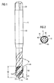
- the tap 5 according to 1 to 3 has a shaft 53 with a thread cutting area 50, which adjoins a free end 55, and a square clamping area 54 for positive clamping in a tool holder or a tool chuck and turning the tap 5 about its axis of rotation A.
- a preferred tool chuck is sold under the mark Softsynchro by the applicant feed or a lining according to EP 0 887 135 B1 ,
- the tap 5 in the thread cutting area 50 has three rows of Gewindeschneidzähnen 10, each along a flute 45 for discharging the thread cutting teeth 10 removed by thread cutting chips at a twist angle or Thisspanwinkel e (see FIG. 1 and 3 ) are arranged, for example, 45 °. However, two or more than three flutes 45 may also be provided.
- the entirety of the thread cutting teeth 10 is along a spiral arrangement under the thread pitch P and under the pitch angle ⁇ (see FIG. 3 ) of the thread to be generated.
- Each thread cutting tooth 10 has a radially outwardly disposed head cutting edge 11 and inwardly extending lateral cutting or edge cutting edges 12 and 13.
- Threading teeth 10 for a metric thread are shown by way of example, in other thread types and shapes such as e.g. Round threads or trapezoidal threads are the thread cutting teeth adapted accordingly in shape.
- An axial coordinate in axial direction r directed away from the free end 55 of the tap toward the axis of rotation A is denoted by z and a radial coordinate extending outwards or perpendicularly from the axis of rotation or the radius is denoted by r.
- the initial radius r1 of the first effective threading tooth substantially corresponds to the radius of the core hole in which the thread is to be produced.
- the thread cutting teeth 10 in the chamfer region 51 now each work the thread over a depth corresponding to the radial distance to the front tooth and depending on .DELTA.r and the total number Z of the teeth in the gate region 51, the so-called gate teeth, further into the workpiece.
- the total depth of the cut thread is then ⁇ r.
- the radial distance r is a linear function of the axial coordinate z, so that a tapered gate portion 51 is realized.
- the difference ri + 1-ri or increase in the radial distance r from an i-th thread cutting tooth 10 to the immediately adjacent i + 1-th thread cutting tooth 10 remains substantially the same over the entire gate region 51 at a value of ⁇ r / Z, so each tooth lifts in about a chip of the same thickness.
- the function of the radial distance r of the head cutting 11 from the axis of rotation A over the gate area 51 need not be a linear function, but may also follow another monotone increasing function over the z-coordinate, so that, for example, a convexly curved gate area results with a axially increasing or decreasing distance difference ri + 1 - ri and thus incorporation depth or chip thickness.
- the gate length La and number of threads of the thread cutting area 50 in the gate area 51 is selected differently for different gate shapes, in particular the aforementioned DIN gate shapes A, B, C, D and E can be used.
- Thread cutting teeth 10 in the gate portion 51 from the number of flutes 45 multiplied by the number of threads.
- the number of threads in the gating region 51 in turn depends on the gating length La and the thread pitch P, which corresponds to the axial distance between two thread cutting teeth 10 on a flute 45 or the axial path of a threading tooth after a complete revolution of the tap.
- the thread cutting area 50 has a guide area 52 adjoining the gate area 51 axially to the axis of rotation A, in which the radial spacing r of the head cutting edges 11 of the thread cutting teeth 10 remains the same at the outside radius r0 or again slightly decreases, but no longer increases.
- a defined rounding, with the life of a tap 5 can be increased, in particular a tap made of hard metal or another brittle hard material when used in particular in steels.
- the rounding at the head cutting 11 is measured or determined at a middle or centrally arranged measuring point P1 along the cutting profile from the rake face to the free face or vice versa in a projection plane E1, for example by means of a known probe, the projection plane E1 perpendicular directed to the cutting edge.
- the fillets 12 and 13 at the edge cutting edges at associated measuring points P2 and P3 by scanning the cutting profile of chip surface to the free surface in each case in a projection plane E2 or E3 perpendicular to the respective cutting edge certainly.
- the fillets on the first threading tooth 10 with full profile are thus determined at the end of the gate area 51 in the transition to the guide area 52, but can also be determined on other teeth (see FIG FIG. 3 ).
- FIG. 4 shows an example of a according to the invention both at the head cutting 11 and the flank cutting edges 12 and 13 rounded thread cutting tooth 10.
- the cutting edge rounding 20 extends substantially parallel over the head cutting edge 11 on the lines 31 and 32, however, that in the cutting corner regions where the head cutting edge 11 merges into the edge cutting edges 12 and 13, the cutting edge rounding becomes larger and the curvature somewhat larger is smaller, based on the there increasing distance between the two lines 31 and 32, and then in the edge cutting 12 and 13 again to remain approximately constant (again almost parallel lines 31 and 32).
- the course of the transition lines 31 and 32 may also be different.
- the lines 31 and 32 may also run away from each other along the flank cutting edges 12 and 13 or occupy a greater distance.
- FIG. 5 now shows an example of a method for determining the radius of curvature for a substantially circular cutting edge rounding. Shown is a projection or a section through a wedge-shaped cutting edge 2 of a thread cutting tooth from the rake surface 21 to the free surface 22. The resulting cutting profile corresponds to the profile or edge of the projected cutting edge 2. The radius or radial distance from the axis of rotation is not shown again r denotes. SR is the cutting direction.
- the end point 20 ' is drawn for an unrounded cutting edge at an outer radius r0.
- the wedge angle of the ideal wedge-shaped cutting profile at the end point 20 ' is denoted by 2 ⁇ 3 and corresponds to the angle between the straight profile section of rake face 21 or the rake face of the ideal wedge-shaped cutting profile on the one hand and the straight profile section of the free surface 22 or the free surface of the ideal wedge-shaped cutting profile on the other ,
- a radial rounding depth t is determined starting from the maximum outer radius r0 radially inward or as a radial depth starting from the original outer radius r0.
- a curvature circle or inner tangential circle is now applied to the rake face 21, which contacts the rake face 21 at point T1, which lies radially at the radius r0-t, and touches the flank face tangentially at point T2 and has the center of curvature M.
- the corresponding this curvature circle rounded from the point T1 on the rake surface 21 to the point T2 on the free surface extending cutting edge or cutting edge rounding as a curved cutting profile curve is denoted by 20.
- FIG. 6 is now the inventively rounded cutting edge according to FIG. 5 additionally represented with a defined reduction depth or removal depth a with respect to the ideal wedge shape or unrounded cutting edge.
- An angle bisector of the ideal wedge shape or unrounded cutting edge is denoted by WH and passes through its end point 20 ', which lies on the linear edge, at the outer radius r0.
- the angle between the bisector WH and the straight profile section of the rake face 21 or the rake face of the ideal wedge-shaped cutting profile on the one hand and the angle between the bisector WH and the rectilinear profile section of the flank 22 or the flank of the ideal wedge-shaped cutting profile on the other hand are equal to each other and each ⁇ 3 designated.
- the wedge angle of the ideal wedge-shaped cutting profile at the end point 20 ' is 2 ⁇ ⁇ 3 and corresponds to the angle between the straight profile section of the rake face 21 or the rake face of the ideal wedge-shaped cutting profile on the one hand and the straight profile section of the flank 22 or the flank of the ideal wedge-shaped cutting profile on the other ,
- the reduction depth or depth of cut a of the rounded cutting edge is the distance, measured along the bisecting line WH of the ideal wedge shape, of the rounded cutting profile curve 20 from the end point 20 'of the ideal wedge shape.
- the rounded cutting edge or its cutting profile curve 20 with the center of curvature M and the radius of curvature R has the reduction depth a
- the rounded, drawn with dashed edge cutting with the minimum radius of curvature Rmin and the center of curvature Mmin has the minimum reduction depth amin
- the rounded, drawn in broken line with the maximum radius of curvature Rmax and the center of curvature Mmax has the maximum reduction depth amax.
- the centers of curvature Mmin, M and Mmax are all on the bisector WH.
- the cutting profile curve 20 of the cutting edge 2 results according to FIG. 5 or FIG. 6 a circle segment, which is best suited for explaining the invention. But you can instead of circular connecting lines between the touch points T1 and T2 in modifications other waveforms, z. As ellipses, hyperbolas, parabolas, trumpet curves or curves composed of different curve sections, etc. with variable radius of curvature in the cutting edge 2 between the rake face 21 and the flank 22 in symmetrical or asymmetrical form to the bisecting WH.
- the transition between the cutting profile curve 20 and the clamping surface 21 and the free surface 22 also need not be tangential or smooth, but can also be done under an edge or corner or the like.
- the radius of curvature R results from the reduction depth a by substituting (5) together with (6) or (7) in (2), (3) or (4).
- the tap teeth of the tap can also be provided with rounding in the outer area between thread cutting and flank cutting and also on the tooth back (back of the groove), for example, for reverse cutting after reversal of direction.
- the thread cutting area, in particular 50 may be formed integrally with the shank 53, e.g. in solid carbide version or as a separate part to the shaft 53 are connected (VHM or KHM). Furthermore, prefabricated parts with thread teeth, e.g. 10 in the form of strips or similar attached to the shaft 53, in particular soldered, clamped or screwed.
- the tap in particular 5, can also be coated with a known hard or wear protection layer or friction reducing layer, e.g. with TiN; TiCN, TiALN, AlCrN or WC / C etc.
- the thread cutting area, in particular 50, or at least the cutting or threading teeth 11 may also be formed from another hard material, for example polycrystalline diamond (PCD), cubic boron nitride (CBN), corundum, a metal boride, in particular magnesium boride, or a metal boride carbide, in particular magnesium boride carbide , or from a non-hard material such as High speed HSS high speed steel.
- PCD polycrystalline diamond
- CBN cubic boron nitride
- corundum corundum
- a metal boride in particular magnesium boride
- a metal boride carbide in particular magnesium boride carbide
- a non-hard material such as High speed HSS high speed steel.
- a shank tolerance h6 is sufficient, but it can also be used eg h9.
- an internal coolant and / or lubricant supply via channels in the tap may be provided, in particular with radial and / or axial outlet.
Landscapes
- Engineering & Computer Science (AREA)
- Mechanical Engineering (AREA)
- Milling Processes (AREA)
- Drilling Tools (AREA)
Claims (15)
- Taraud (5),a) qui peut tourner autour d'un axe de rotation (A) etb) qui présente une pluralité de dents de filetage (10) qui présentent chacune une tête tranchante (11) située du côté extérieur en position radiale et sont agencées en décalage l'une par rapport à l'autre avec un pas de vis (P) prédéfini dans un agencement entourant l'axe de rotation (A) en forme de spirale ou d'hélice,c) dans lequel dans une zone de découpe (51) adjacente à une extrémité du taraud (5) en direction axiale par rapport à l'axe de rotation (A), la distance radiale maximale entre les têtes tranchantes (11) des dents de filetage (10) et l'axe de rotation (A) augmente selon une fonction de distance radiale prédéfinie à mesure que la distance axiale entre les têtes tranchantes (11) et une extrémité du taraud (5) augmente,d) dans lequel la direction radiale est définie comme étant perpendiculaire à l'axe de rotation (A) et la direction axiale est définie comme longeant ou étant parallèle à l'axe de rotation (A),e) caractérisé en ce qu'au moins une partie des dents de filetage (10) présentent chacune dans la zone de découpe (51), au moins dans la zone des têtes tranchantes (11), un arrondi défini de leur tranchant (20) entre la face d'attaque (21) et la face de dépouille (22), étant entendu que les courbures des arrondis du tranchant (20) et/ou les profondeurs de diminution des arrondis du tranchant (20) par rapport à une forme de coin idéale (20') ou à l'arête tranchante non arrondie sont chacune choisies en fonctione1) du nombre de dents de filetage (10) dans la zone de découpe (51) ete2) du pas de vis (P),f) étant entendu que les rayons de courbure des arrondis du tranchant (20) d'au moins une partie des dents de filetage (10) dans la zone de découpe (51), au moins dans la zone de leur tête tranchante (11), sont choisis selon l'équation

et que les profondeurs de diminution des arrondis du tranchant (20) d'au moins une partie des dents de filetage (10) dans la zone de découpe (51), au moins dans la zone de leur tête tranchante (11), sont choisies selon l'équation
étant entendu que R désigne le rayon de courbure, 2γ3 l'angle du coin, f (γ3) une fonction de l'angle du coin 2γ3, P le pas de vis et Z le nombre de dents de filetage dans la zone de découpe et que
C est un nombre réel conforme à
- Taraud (5) selon la revendication 1, dans lequel les courbures des arrondis du tranchant (20) et/ou les profondeurs de diminution des arrondis du tranchant (20) par rapport à une forme de coin idéale (20') ou à l'arête tranchante non arrondie sont chacune choisies selon l'augmentation de la distance radiale maximale des têtes tranchantes (11) des dents de filetage (10) dans la zone de découpe (51) ou selon la fonction de distance radiale des dents de filetage (10) dans la zone de découpe (51).
- Taraud (5) selon la revendication 1 ou la revendication 2, dans lequel les rayons de courbure des arrondis du tranchant (20) et/ou les profondeurs de diminution des arrondis du tranchant (20) des dents de filetage (10) dans la zone de découpe (51) sont à chaque fois plus petits au moins en moyenne :- lorsque pour un même pas de vis (P) et/ou pour une même fonction de distance radiale, le nombre de dents de filetage (10) dans la zone de découpe (51) est plus élevé,
ou- lorsque pour un même nombre de dents de filetage (10) dans la zone de découpe (51) et/ou pour un même pas de vis (P), l'augmentation de la distance radiale maximale dans l'ensemble de la zone de découpe (51) selon la fonction de distance radiale est plus faible,
ou- lorsque pour une même fonction de distance radiale et/ou pour un même nombre de dents de filetage (10) dans la zone de découpe (51), le pas de vis (P) est plus petit. - Taraud (5) selon l'une des revendications précédentes, dans lequel la fonction de distance radiale des moyens de filetage dans la zone de découpe (51) est croissante de façon monotone, de préférence rigoureusement monotone, et/ou dans lequel la fonction de distance radiale pour la distance radiale maximale des têtes tranchantes (11) est une fonction linéaire ou une fonction discontinue ou échelonnée de la distance axiale depuis l'extrémité du taraud (5),
et/ou
dans lequel la fonction de distance radiale pour la distance radiale maximale des têtes tranchantes (11) est choisie dans un groupe de fonctions comprenant une fonction rationnelle ou rationnelle fractionnaire d'ordre n, en particulier un polynôme d'ordre n, une fonction de racine ou de puissance, une fonction exponentielle ou une fonction logarithmique, une fonction de spirale, en particulier une spirale logarithmique ou d'Archimède ou une fonction interpolée, en particulier au moyen de polynômes d'interpolation de Lagrange ou de fonctions spline. - Taraud (5) selon l'une des revendications précédentes comprenant une zone de guidage (52) faisant suite à la section de découpe (51) dans la direction radiale, dans laquelle l'agencement des dents de filetage (10) continue et dans laquelle la distance radiale maximale des têtes tranchantes (11) des dents de filetage (10) n'augmente plus, et en particulier, reste constante et diminue ensuite légèrement, à mesure que la distance axiale à partir d'une extrémité du taraud (5) augmente, étant entendu que de préférence, au moins une partie des dents de filetage (10) dans la zone de guidage (52), au moins dans la zone des têtes tranchantes (11), présentent chacune un arrondi défini de leur tranchant (20), étant entendu que de préférence, les courbures des arrondis du tranchant (20) et/ou les profondeurs de diminution des arrondis du tranchant (20) sont chacune choisies en fonction du pas de vis (P).
- Taraud (5) selon l'une des revendications précédentes, dans lequel les rayons de courbure des arrondis du tranchant (20) peuvent varier ou se situent à l'intérieur d'une marge de 2 µm à 200 µm, de préférence à l'intérieur d'une marge de 18 µm à 100 µm ou de 5 µm à 60 µm, ou dans lequel les arrondis du tranchant (20) des dents de filetage (10) sont réalisés avec des courbes de profilé de filetage courbées entre la face d'attaque (21) et la face de dépouille (22).
- Taraud (5) selon l'une des revendications précédentes, dans lequel au moins un arrondi de tranchant (20) ou au moins une courbe de profilé de filetage s'étend sensiblement le long d'un cercle de courbure ou en forme d'arc de cercle, au moins sur une certaine section, ou présente une courbure ou un rayon de courbure sensiblement constant(e) au moins sur une certaine section,
et/ou
dans lequel au moins un arrondi de tranchant (20) ou au moins une courbe de profilé de filetage a sensiblement un tracé qui n'est pas en forme d'arc de cercle, au moins sur une certaine section, en particulier selon une fonction rationnelle ou rationnelle fractionnaire d'ordre n, en particulier un polynôme d'ordre n, une fonction de racine ou de puissance, une fonction exponentielle ou logarithmique, une fonction de spirale, en particulier une spirale logarithmique ou d'Archimède, ou une fonction interpolée, en particulier au moyen de polynômes d'interpolation de Lagrange ou de fonctions spline,
ou dans lequel au moins un arrondi de tranchant (20) ou au moins une courbe de profilé de filetage présente une courbure ou un rayon de courbure (R) sensiblement variable ou non constant(e), au moins sur une certaine section. - Taraud (5) selon la revendication 7, dans lequel la courbure d'au moins un arrondi de tranchant (20) ou d'au moins une courbe de profilé de filetage augmente ou diminue depuis la face d'attaque (21) vers la face de dépouille (22),
ou
dans lequel la courbure d'au moins un arrondi de tranchant (20) ou d'au moins une courbe de profilé de filetage augmente jusqu'à un maximum, puis diminue à nouveau, depuis la face d'attaque (21) vers la face de dépouille (22),
ou
dans lequel la courbure d'au moins un arrondi de tranchant (20) ou d'au moins une courbe de profilé de filetage diminue jusqu'à un minimum, puis augmente à nouveau, depuis la face d'attaque (21) vers la face de dépouille (22), ou dans lequel la courbure prédéfinie de l'arrondi de tranchant (20) est prévue dans une zone centrale des têtes tranchantes (11) et une autre courbure ou bien une forme d'arête pratiquement sans courbure est prévue dans les zones de transition vers les zones de flanc ou les angles de filetage des dents de filetage (10). - Taraud (5) selon l'une des revendications précédentes, dans lequel entre l'arrondi des tranchants (20) dans la face d'attaque (21) et/ou la face de dépouille (22), le tranchant correspondant s'étend de façon tangentielle ou de façon constamment différenciable ou de façon lisse,
et/ou
dans lequel la courbure ou au moins un rayon de courbure de l'arrondi des tranchants (20) se situe dans un intervalle de valeurs prédéfini qui est déterminé en fonction d'une profondeur d'arrondi (t). - Taraud (5) selon l'une des revendications précédentes, dans lequel les courbures des arrondis des tranchants (20) ou les courbes des profilés de filetage et/ou les profondeurs de diminution des arrondis des tranchants (20) sont fonction du diamètre du filetage et/ou fonction de l'angle d'attaque de la face d'attaque (21) et/ou de l'angle de dépouille de la face de dépouille (22) et/ou de l'angle de coin de la forme de coin idéale et/ou de l'angle d'attaque latéral de la découpe et/ou fonction du matériau dans lequel le filetage doit être produit et/ou du matériau des dents de filetage (10) et/ou de leur état comme leur structure et/ou leur dureté.
- Taraud (5) selon l'une des revendications précédentes comprenant au moins deux rainures d'attaque (45) qui s'étendent parallèlement ou dans la direction axiale par rapport à l'axe de rotation ou qui entourent l'axe de rotation (A) avec un angle de torsion variable ou constant, étant entendu qu'au moins une et de préférence plusieurs dents de filetage (10) décalées dans la direction radiale sont respectivement agencées au niveau de chaque rainure d'attaque (45), étant entendu que les courbures des arrondis des tranchants (20) ou les courbes des profilés de filetage et/ou les profondeurs de diminution des arrondis des tranchants (20) sont choisies respectivement en fonction du nombre de rainures d'attaque (45) et/ou de l'angle de torsion des rainures d'attaque (45).
- Taraud (5) selon l'une des revendications précédentes, dans lequel le nombre réel C est conforme à

- Taraud (5) selon l'une des revendications précédentes, dans lequel au moins les dents de filetage (10), au moins au niveau des têtes tranchantes (11), sont réalisées dans un métal dur ou un carbure métallique ou dans un autre matériau dur, en particulier cassant, en particulier le diamant polycristallin (PCD), le nitrure de bore cubique (CBN), le corindon, un borure de métal, en particulier un borure de magnésium, ou un carbure de borure de métal, en particulier un carbure de borure de magnésium.
- Ensemble de tarauds (5) selon l'une des revendications précédentes, dans lequel les tarauds (5) se distinguent dans le nombre de dents de filetage (10) dans la zone de découpe (51) et/ou dans l'augmentation de la distance radiale maximale des têtes tranchantes (11) des dents de filetage (10) dans la zone de découpe (51) ou la fonction de distance radiale des dents de filetage (10) dans la zone de découpe (51) et/ou dans le pas de vis (P), et parmi les différents tarauds (5), les courbures des arrondis des arêtes tranchantes (20) d'au moins une partie des dents de filetage (10) se distinguent dans la zone de découpe (51), au moins dans la zone des têtes tranchantes (11), en fonction du ou des paramètres précités.
- Procédé de fabrication de tarauds (5) qui peuvent tourner autour d'un axe de rotation (A), dans lequel :a) pour chaque taraud (5), un nombre correspondant de dents de filetage (10) est produit, lesquelles présentent chacune une tête tranchante (11) située du côté extérieur en position radiale et sont agencées en décalage l'une par rapport à l'autre avec un pas de vis (P) prédéfini dans un agencement entourant l'axe de rotation (A) en forme de spirale ou d'hélice,c) dans lequel dans une zone de découpe (51) adjacente à une extrémité du taraud (5) en direction axiale par rapport à l'axe de rotation (A), la distance radiale maximale entre les têtes tranchantes (11) des dents de filetage (10) et l'axe de rotation (A) augmente selon une fonction de distance radiale prédéfinie à mesure que la distance axiale entre les têtes tranchantes (11) et une extrémité du taraud (5) augmente,d) dans lequel la direction radiale est définie comme étant perpendiculaire à l'axe de rotation (A) et la direction axiale est définie comme longeant ou étant parallèle à l'axe de rotation (A),e) caractérisé en ce qu'au moins une partie des dents de filetage (10) sont chacune munies ou fabriquées, dans la zone de découpe (51), au moins dans la zone des têtes tranchantes (11), avec à chaque fois un arrondi de leur arête tranchante (20) ayant une courbure définie, étant entendu que :l es courbures des arrondis des arêtes tranchantes (20) et/ou les profondeurs de diminution des arêtes tranchantes arrondies par rapport à une forme de coin idéale ou à une arête tranchante non arrondie sont chacune choisies ou ajustées en fonction e1) du nombre de dents de filetage (11) dans la zone de découpe (51) ete2) du pas de vis (P), ete3) de préférence également de l'augmentation de la distance radiale maximale des têtes tranchantes (11) des dents de filetage (10) dans la zone de découpe (51) ou de la fonction de distance radiale des dents de filetage (10) dans la zone de découpe (51) du taraud (5) respectif,f) étant entendu que les rayons de courbure des arrondis du tranchant (20) d'au moins une partie des dents de filetage (10) dans la zone de découpe (51), au moins dans la zone de leur tête tranchante (11), sont choisis selon l'équation

et que les profondeurs de diminution des arrondis du tranchant (20) d'au moins une partie des dents de filetage (10) dans la zone de découpe (51), au moins dans la zone de leur tête tranchante (11), sont choisies selon l'équation
étant entendu que R désigne le rayon de courbure, 2γ3 l'angle du coin, f (γ3) une fonction de l'angle du coin 2γ3, P le pas de vis (P) et Z le nombre de dents de filetage (10) dans la zone de découpe (51) et que
C est un nombre réel conforme à g) étant entendu que de préférence, les dents de filetage (10) ayant des arêtes tranchantes non encore arrondies sont réalisées par meulage et/ou
étant entendu que de préférence, un procédé mécanique d'enlèvement fin de matériau, en particulier un procédé de meulage à projection ou d'attaque à projection avec un matériau abrasif, un procédé de brossage ou un procédé de projection d'eau à haute pression, est mis en oeuvre afin d'arrondir les arêtes tranchantes des dents de filetage (10).
Applications Claiming Priority (2)
| Application Number | Priority Date | Filing Date | Title |
|---|---|---|---|
| DE102007060354 | 2007-12-12 | ||
| PCT/EP2008/010609 WO2009074343A1 (fr) | 2007-12-12 | 2008-12-12 | Taraud et procédé pour produire un taraud |
Publications (2)
| Publication Number | Publication Date |
|---|---|
| EP2229257A1 EP2229257A1 (fr) | 2010-09-22 |
| EP2229257B1 true EP2229257B1 (fr) | 2013-07-24 |
Family
ID=40592101
Family Applications (1)
| Application Number | Title | Priority Date | Filing Date |
|---|---|---|---|
| EP08859233.2A Active EP2229257B1 (fr) | 2007-12-12 | 2008-12-12 | Taraud et procédé pour produire un taraud |
Country Status (4)
| Country | Link |
|---|---|
| US (1) | US9033624B2 (fr) |
| EP (1) | EP2229257B1 (fr) |
| CN (1) | CN101896306B (fr) |
| WO (1) | WO2009074343A1 (fr) |
Cited By (1)
| Publication number | Priority date | Publication date | Assignee | Title |
|---|---|---|---|---|
| WO2021052835A1 (fr) | 2019-09-16 | 2021-03-25 | EMUGE-Werk Richard Glimpel GmbH & Co. KG Fabrik für Präzisionswerkzeuge | Procédé pour générer un filet présentant un pas de filetage prédéfini dans un avant-trou ménagé dans une pièce |
Families Citing this family (27)
| Publication number | Priority date | Publication date | Assignee | Title |
|---|---|---|---|---|
| WO2008136123A1 (fr) * | 2007-04-26 | 2008-11-13 | Osg Corporation | Taraud hélicoïdal |
| US8210779B2 (en) * | 2008-10-14 | 2012-07-03 | Kennametal Inc. | Cutting tap and method of making same |
| DE102008053772A1 (de) * | 2008-10-22 | 2010-04-29 | Komet Jel Precision Tools | Gewindeformer |
| US20110200404A1 (en) * | 2008-10-27 | 2011-08-18 | Osg Corporation | Spiral tap |
| DE112009005043B4 (de) * | 2009-07-07 | 2021-12-30 | Osg Corp. | Gewindeausbildungsbohrer |
| US9539652B2 (en) | 2010-04-30 | 2017-01-10 | Kennametal Inc. | Rotary cutting tool having PCD cutting tip |
| DE102011075770A1 (de) * | 2011-05-12 | 2012-11-15 | Hilti Aktiengesellschaft | Verfahren zum Ausformen eines Innengewindes sowie Kombination aus einem Grundkörper mit einer Ausnehmung und einem Gewindeschneider |
| US9604298B2 (en) * | 2011-08-25 | 2017-03-28 | Ricoh Elemex Corporation | Method of manufacturing screw thread and screw thread |
| CN104271298A (zh) * | 2012-03-27 | 2015-01-07 | 斯皮塔普工业股份有限公司 | 攻丝装置及使用方法 |
| WO2014167984A1 (fr) * | 2013-04-08 | 2014-10-16 | 有限会社ジュコー精機 | Outil de coupe pour usiner un écrou d'un dispositif à vis coulissante, et procédé pour usiner un écrou |
| DE102013103538A1 (de) * | 2013-04-09 | 2014-10-09 | EMUGE-Werk Richard Glimpel GmbH & Co. KG Fabrik für Präzisionswerkzeuge | Werkzeug und Verfahren zur spanenden Gewindeerzeugung |
| WO2015137445A1 (fr) * | 2014-03-13 | 2015-09-17 | 株式会社ミヤギタノイ | Taraud de coupe |
| US9839984B2 (en) | 2014-08-14 | 2017-12-12 | Kennametal Inc. | Method of making a cutting tap with a correction grind |
| CN104385466A (zh) * | 2014-09-22 | 2015-03-04 | 东莞信柏结构陶瓷有限公司 | 一种陶瓷螺纹加工刀具及陶瓷螺纹加工方法 |
| DE102015009017A1 (de) * | 2015-07-10 | 2017-01-12 | Liebherr-Verzahntechnik Gmbh | Verfahren zur Herstellung eines verzahnten Werkstückes mit modifizierter Oberflächengeometrie |
| BR112018011207B1 (pt) | 2015-12-02 | 2022-12-06 | Osg Corporation | Torneira em espiral |
| RU2616755C1 (ru) * | 2015-12-09 | 2017-04-18 | федеральное государственное бюджетное образовательное учреждение высшего образования "Санкт-Петербургский горный университет" | Метчик для нарезания точных резьб |
| US10766083B2 (en) | 2017-05-31 | 2020-09-08 | Kennametal Inc. | Spiral flute tap with continuously increasing helix angle |
| JP7218042B2 (ja) * | 2017-08-04 | 2023-02-06 | エリコン サーフェス ソリューションズ アーゲー、 プフェフィコン | 性能を強化したタップドリル |
| CN109648022B (zh) * | 2019-02-02 | 2024-01-23 | 张咏 | 一种无缝无毛刺挤压丝锥及其制作的内螺纹 |
| CN110202221B (zh) * | 2019-05-29 | 2020-08-25 | 西安法士特汽车传动有限公司 | 一种先端丝锥及其应用 |
| DE102019124707B4 (de) | 2019-09-13 | 2022-05-19 | EMUGE-Werk Richard Glimpel GmbH & Co. KG Fabrik für Präzisionswerkzeuge | Verfahren zum Erzeugen eines Gewindes mit Übersetzungseinheit |
| JP7297943B2 (ja) * | 2020-01-21 | 2023-06-26 | オーエスジー株式会社 | ボールねじ用盛上げタップ |
| US11759914B2 (en) | 2020-08-06 | 2023-09-19 | Mate Precision Technologies Inc. | Vise assembly |
| WO2022032148A1 (fr) | 2020-08-06 | 2022-02-10 | Mate Precision Technologies Inc. | Ensemble base d'usinage |
| CN115592215B (zh) * | 2022-11-11 | 2025-07-15 | 上海铼钠克信息技术有限公司 | 挤压丝锥磨削方法及系统 |
| CN117763763B (zh) * | 2024-01-02 | 2024-06-14 | 上海交通大学 | 用于角区流动控制的压气机叶根轴向非均匀倒圆优化方法 |
Family Cites Families (15)
| Publication number | Priority date | Publication date | Assignee | Title |
|---|---|---|---|---|
| US1718536A (en) * | 1927-07-25 | 1929-06-25 | More Tap & Tool Company Du | Tap |
| US2556174A (en) * | 1943-10-09 | 1951-06-12 | Lock Thread Corp | Screw-thread swaging tool |
| US3021538A (en) * | 1956-04-16 | 1962-02-20 | Universal Thread Grinding Comp | Thread cutting tool with dulled edges on the guide teeth portion |
| SU1235673A1 (ru) * | 1984-12-10 | 1986-06-07 | Челябинский Конструкторско-Технологический Институт Автоматизации И Механизации Автомобилестроения | Метчик |
| CN2172690Y (zh) * | 1993-02-27 | 1994-07-27 | 天津中德现代工业技术培训中心 | 大直径螺纹槽丝锥 |
| CN2202606Y (zh) * | 1994-10-14 | 1995-07-05 | 汲伟民 | 斜刃丝锥 |
| US6105467A (en) * | 1998-06-26 | 2000-08-22 | Baker; David A. | Method for preparing a cutting edge on an end mill |
| US6345941B1 (en) * | 2000-02-23 | 2002-02-12 | Ati Properties, Inc. | Thread milling tool having helical flutes |
| US7147939B2 (en) | 2003-02-27 | 2006-12-12 | Kennametal Inc. | Coated carbide tap |
| US7147413B2 (en) | 2003-02-27 | 2006-12-12 | Kennametal Inc. | Precision cemented carbide threading tap |
| JP3787124B2 (ja) * | 2003-03-14 | 2006-06-21 | 株式会社彌満和製作所 | 高速加工用タップ |
| DE10332930A1 (de) * | 2003-07-19 | 2005-02-03 | Sandvik Ab | Gewindebohrer |
| DE102004047839A1 (de) * | 2004-09-29 | 2006-03-30 | Sandvik Intellectual Property Hb | Gewindeschneidwerkzeug |
| DE102006027232B4 (de) * | 2006-06-09 | 2025-08-14 | EMUGE-Werk Richard Glimpel GmbH & Co. KG Fabrik für Präzisionswerkzeuge | Gewindebohrer mit Kantenübergang |
| US7665934B2 (en) * | 2006-10-18 | 2010-02-23 | Kennametal Inc. | Cutting tap and method of making a cutting tap |
-
2008
- 2008-12-12 EP EP08859233.2A patent/EP2229257B1/fr active Active
- 2008-12-12 WO PCT/EP2008/010609 patent/WO2009074343A1/fr not_active Ceased
- 2008-12-12 CN CN200880120564.1A patent/CN101896306B/zh not_active Expired - Fee Related
- 2008-12-12 US US12/747,146 patent/US9033624B2/en active Active
Cited By (2)
| Publication number | Priority date | Publication date | Assignee | Title |
|---|---|---|---|---|
| WO2021052835A1 (fr) | 2019-09-16 | 2021-03-25 | EMUGE-Werk Richard Glimpel GmbH & Co. KG Fabrik für Präzisionswerkzeuge | Procédé pour générer un filet présentant un pas de filetage prédéfini dans un avant-trou ménagé dans une pièce |
| DE102019124800B4 (de) | 2019-09-16 | 2024-09-19 | EMUGE-Werk Richard Glimpel GmbH & Co. KG Fabrik für Präzisionswerkzeuge | Verfahren zum Erzeugen eines Gewindes, insbesondere eines Innengewindes, mit Hartmetall |
Also Published As
| Publication number | Publication date |
|---|---|
| CN101896306A (zh) | 2010-11-24 |
| WO2009074343A1 (fr) | 2009-06-18 |
| US9033624B2 (en) | 2015-05-19 |
| CN101896306B (zh) | 2013-05-08 |
| EP2229257A1 (fr) | 2010-09-22 |
| US20100260566A1 (en) | 2010-10-14 |
Similar Documents
| Publication | Publication Date | Title |
|---|---|---|
| EP2229257B1 (fr) | Taraud et procédé pour produire un taraud | |
| DE69408611T2 (de) | Gewindebohrer | |
| DE112007003489B4 (de) | Spiralgewindebohrer | |
| DE102004059264B4 (de) | Werkzeug und Verfahren zur Erzeugung eines Gewindes in einem Werkstück | |
| EP0904880B1 (fr) | Fraise à fileter pour matériaux tenaces | |
| EP3356071B1 (fr) | Outil de fraisage de finition, en particulier fraise à queue | |
| EP3710194B1 (fr) | Outil et procédé permettant de produire un filetage, en particulier un filetage intérieur | |
| DE102009028040B4 (de) | Kombinationswerkzeug für die Strukturierung von Oberflächen | |
| WO2016020047A1 (fr) | Outil de fraisage | |
| DE102006010651A1 (de) | Kombinationswerkzeug mit Stirnaussparung | |
| DE202016106331U1 (de) | Gewindewerkzeuge mit Fluidkanälen | |
| WO2004094094A1 (fr) | Procede, outil et dispositif pour la realisation de taraudages | |
| DE102005022503B4 (de) | Werkzeug und Verfahren zur Erzeugung eines Gewindes | |
| EP2929966B1 (fr) | Outil de fraisage complet pour l'usinage rotatif de matériaux | |
| DE20015550U1 (de) | Stufenbohrer | |
| DE10318948A1 (de) | Kombinationswerkzeug | |
| DE102019124800B4 (de) | Verfahren zum Erzeugen eines Gewindes, insbesondere eines Innengewindes, mit Hartmetall | |
| WO2025181358A1 (fr) | Fraise et son utilisation | |
| DE102005009829A1 (de) | Werkzeug und Verfahren zur Erzeugung eines Gewindes | |
| DE102005019921A1 (de) | Werkzeug und Verfahren zur Erzeugung oder Nachbearbeitung eines Gewindes | |
| DE102010025148A1 (de) | Spanabhebendes Werkzeug | |
| WO2004022274A1 (fr) | Fraise a fileter | |
| DE102005010543B4 (de) | Werkzeug und Verfahren zur Erzeugung oder Nachbearbeitung eines Gewindes | |
| DE102005037309B4 (de) | Werkzeug und Verfahren zur Erzeugung oder Nachbearbeitung eines Gewindes | |
| DE112015002327B4 (de) | Gewindeformwerkzeug mit gotischem Gewindeprofil und Verfahren zur Herstellung eines solchen Gewindeformwerkzeugs |
Legal Events
| Date | Code | Title | Description |
|---|---|---|---|
| PUAI | Public reference made under article 153(3) epc to a published international application that has entered the european phase |
Free format text: ORIGINAL CODE: 0009012 |
|
| 17P | Request for examination filed |
Effective date: 20100331 |
|
| AK | Designated contracting states |
Kind code of ref document: A1 Designated state(s): AT BE BG CH CY CZ DE DK EE ES FI FR GB GR HR HU IE IS IT LI LT LU LV MC MT NL NO PL PT RO SE SI SK TR |
|
| AX | Request for extension of the european patent |
Extension state: AL BA MK RS |
|
| DAX | Request for extension of the european patent (deleted) | ||
| GRAP | Despatch of communication of intention to grant a patent |
Free format text: ORIGINAL CODE: EPIDOSNIGR1 |
|
| GRAS | Grant fee paid |
Free format text: ORIGINAL CODE: EPIDOSNIGR3 |
|
| GRAA | (expected) grant |
Free format text: ORIGINAL CODE: 0009210 |
|
| AK | Designated contracting states |
Kind code of ref document: B1 Designated state(s): AT BE BG CH CY CZ DE DK EE ES FI FR GB GR HR HU IE IS IT LI LT LU LV MC MT NL NO PL PT RO SE SI SK TR |
|
| REG | Reference to a national code |
Ref country code: GB Ref legal event code: FG4D Free format text: NOT ENGLISH |
|
| REG | Reference to a national code |
Ref country code: CH Ref legal event code: EP |
|
| REG | Reference to a national code |
Ref country code: AT Ref legal event code: REF Ref document number: 623103 Country of ref document: AT Kind code of ref document: T Effective date: 20130815 |
|
| REG | Reference to a national code |
Ref country code: IE Ref legal event code: FG4D Free format text: LANGUAGE OF EP DOCUMENT: GERMAN |
|
| REG | Reference to a national code |
Ref country code: DE Ref legal event code: R096 Ref document number: 502008010385 Country of ref document: DE Effective date: 20130926 |
|
| REG | Reference to a national code |
Ref country code: NL Ref legal event code: VDEP Effective date: 20130724 |
|
| REG | Reference to a national code |
Ref country code: LT Ref legal event code: MG4D |
|
| PG25 | Lapsed in a contracting state [announced via postgrant information from national office to epo] |
Ref country code: LT Free format text: LAPSE BECAUSE OF FAILURE TO SUBMIT A TRANSLATION OF THE DESCRIPTION OR TO PAY THE FEE WITHIN THE PRESCRIBED TIME-LIMIT Effective date: 20130724 Ref country code: SE Free format text: LAPSE BECAUSE OF FAILURE TO SUBMIT A TRANSLATION OF THE DESCRIPTION OR TO PAY THE FEE WITHIN THE PRESCRIBED TIME-LIMIT Effective date: 20130724 Ref country code: CY Free format text: LAPSE BECAUSE OF FAILURE TO SUBMIT A TRANSLATION OF THE DESCRIPTION OR TO PAY THE FEE WITHIN THE PRESCRIBED TIME-LIMIT Effective date: 20130904 Ref country code: PT Free format text: LAPSE BECAUSE OF FAILURE TO SUBMIT A TRANSLATION OF THE DESCRIPTION OR TO PAY THE FEE WITHIN THE PRESCRIBED TIME-LIMIT Effective date: 20131125 Ref country code: HR Free format text: LAPSE BECAUSE OF FAILURE TO SUBMIT A TRANSLATION OF THE DESCRIPTION OR TO PAY THE FEE WITHIN THE PRESCRIBED TIME-LIMIT Effective date: 20130724 Ref country code: IS Free format text: LAPSE BECAUSE OF FAILURE TO SUBMIT A TRANSLATION OF THE DESCRIPTION OR TO PAY THE FEE WITHIN THE PRESCRIBED TIME-LIMIT Effective date: 20131124 Ref country code: NO Free format text: LAPSE BECAUSE OF FAILURE TO SUBMIT A TRANSLATION OF THE DESCRIPTION OR TO PAY THE FEE WITHIN THE PRESCRIBED TIME-LIMIT Effective date: 20131024 |
|
| PG25 | Lapsed in a contracting state [announced via postgrant information from national office to epo] |
Ref country code: PL Free format text: LAPSE BECAUSE OF FAILURE TO SUBMIT A TRANSLATION OF THE DESCRIPTION OR TO PAY THE FEE WITHIN THE PRESCRIBED TIME-LIMIT Effective date: 20130724 Ref country code: GR Free format text: LAPSE BECAUSE OF FAILURE TO SUBMIT A TRANSLATION OF THE DESCRIPTION OR TO PAY THE FEE WITHIN THE PRESCRIBED TIME-LIMIT Effective date: 20131025 Ref country code: LV Free format text: LAPSE BECAUSE OF FAILURE TO SUBMIT A TRANSLATION OF THE DESCRIPTION OR TO PAY THE FEE WITHIN THE PRESCRIBED TIME-LIMIT Effective date: 20130724 Ref country code: FI Free format text: LAPSE BECAUSE OF FAILURE TO SUBMIT A TRANSLATION OF THE DESCRIPTION OR TO PAY THE FEE WITHIN THE PRESCRIBED TIME-LIMIT Effective date: 20130724 Ref country code: NL Free format text: LAPSE BECAUSE OF FAILURE TO SUBMIT A TRANSLATION OF THE DESCRIPTION OR TO PAY THE FEE WITHIN THE PRESCRIBED TIME-LIMIT Effective date: 20130724 Ref country code: SI Free format text: LAPSE BECAUSE OF FAILURE TO SUBMIT A TRANSLATION OF THE DESCRIPTION OR TO PAY THE FEE WITHIN THE PRESCRIBED TIME-LIMIT Effective date: 20130724 |
|
| PG25 | Lapsed in a contracting state [announced via postgrant information from national office to epo] |
Ref country code: CY Free format text: LAPSE BECAUSE OF FAILURE TO SUBMIT A TRANSLATION OF THE DESCRIPTION OR TO PAY THE FEE WITHIN THE PRESCRIBED TIME-LIMIT Effective date: 20130724 |
|
| PG25 | Lapsed in a contracting state [announced via postgrant information from national office to epo] |
Ref country code: CZ Free format text: LAPSE BECAUSE OF FAILURE TO SUBMIT A TRANSLATION OF THE DESCRIPTION OR TO PAY THE FEE WITHIN THE PRESCRIBED TIME-LIMIT Effective date: 20130724 Ref country code: RO Free format text: LAPSE BECAUSE OF FAILURE TO SUBMIT A TRANSLATION OF THE DESCRIPTION OR TO PAY THE FEE WITHIN THE PRESCRIBED TIME-LIMIT Effective date: 20130724 Ref country code: DK Free format text: LAPSE BECAUSE OF FAILURE TO SUBMIT A TRANSLATION OF THE DESCRIPTION OR TO PAY THE FEE WITHIN THE PRESCRIBED TIME-LIMIT Effective date: 20130724 Ref country code: EE Free format text: LAPSE BECAUSE OF FAILURE TO SUBMIT A TRANSLATION OF THE DESCRIPTION OR TO PAY THE FEE WITHIN THE PRESCRIBED TIME-LIMIT Effective date: 20130724 Ref country code: SK Free format text: LAPSE BECAUSE OF FAILURE TO SUBMIT A TRANSLATION OF THE DESCRIPTION OR TO PAY THE FEE WITHIN THE PRESCRIBED TIME-LIMIT Effective date: 20130724 |
|
| PG25 | Lapsed in a contracting state [announced via postgrant information from national office to epo] |
Ref country code: ES Free format text: LAPSE BECAUSE OF FAILURE TO SUBMIT A TRANSLATION OF THE DESCRIPTION OR TO PAY THE FEE WITHIN THE PRESCRIBED TIME-LIMIT Effective date: 20130724 Ref country code: IT Free format text: LAPSE BECAUSE OF FAILURE TO SUBMIT A TRANSLATION OF THE DESCRIPTION OR TO PAY THE FEE WITHIN THE PRESCRIBED TIME-LIMIT Effective date: 20130724 |
|
| PLBE | No opposition filed within time limit |
Free format text: ORIGINAL CODE: 0009261 |
|
| STAA | Information on the status of an ep patent application or granted ep patent |
Free format text: STATUS: NO OPPOSITION FILED WITHIN TIME LIMIT |
|
| BERE | Be: lapsed |
Owner name: EMUGE-WERK RICHARD GLIMPEL G.M.B.H. & CO.KG FABRIK Effective date: 20131231 |
|
| 26N | No opposition filed |
Effective date: 20140425 |
|
| REG | Reference to a national code |
Ref country code: CH Ref legal event code: PL |
|
| REG | Reference to a national code |
Ref country code: DE Ref legal event code: R097 Ref document number: 502008010385 Country of ref document: DE Effective date: 20140425 |
|
| GBPC | Gb: european patent ceased through non-payment of renewal fee |
Effective date: 20131212 |
|
| PG25 | Lapsed in a contracting state [announced via postgrant information from national office to epo] |
Ref country code: LU Free format text: LAPSE BECAUSE OF FAILURE TO SUBMIT A TRANSLATION OF THE DESCRIPTION OR TO PAY THE FEE WITHIN THE PRESCRIBED TIME-LIMIT Effective date: 20131212 Ref country code: MC Free format text: LAPSE BECAUSE OF FAILURE TO SUBMIT A TRANSLATION OF THE DESCRIPTION OR TO PAY THE FEE WITHIN THE PRESCRIBED TIME-LIMIT Effective date: 20130724 |
|
| REG | Reference to a national code |
Ref country code: IE Ref legal event code: MM4A |
|
| REG | Reference to a national code |
Ref country code: FR Ref legal event code: ST Effective date: 20140829 |
|
| PG25 | Lapsed in a contracting state [announced via postgrant information from national office to epo] |
Ref country code: LI Free format text: LAPSE BECAUSE OF NON-PAYMENT OF DUE FEES Effective date: 20131231 Ref country code: BE Free format text: LAPSE BECAUSE OF NON-PAYMENT OF DUE FEES Effective date: 20131231 Ref country code: CH Free format text: LAPSE BECAUSE OF NON-PAYMENT OF DUE FEES Effective date: 20131231 Ref country code: IE Free format text: LAPSE BECAUSE OF NON-PAYMENT OF DUE FEES Effective date: 20131212 |
|
| PG25 | Lapsed in a contracting state [announced via postgrant information from national office to epo] |
Ref country code: FR Free format text: LAPSE BECAUSE OF NON-PAYMENT OF DUE FEES Effective date: 20131231 Ref country code: GB Free format text: LAPSE BECAUSE OF NON-PAYMENT OF DUE FEES Effective date: 20131212 |
|
| REG | Reference to a national code |
Ref country code: AT Ref legal event code: MM01 Ref document number: 623103 Country of ref document: AT Kind code of ref document: T Effective date: 20131212 |
|
| PG25 | Lapsed in a contracting state [announced via postgrant information from national office to epo] |
Ref country code: AT Free format text: LAPSE BECAUSE OF NON-PAYMENT OF DUE FEES Effective date: 20131212 |
|
| PG25 | Lapsed in a contracting state [announced via postgrant information from national office to epo] |
Ref country code: TR Free format text: LAPSE BECAUSE OF FAILURE TO SUBMIT A TRANSLATION OF THE DESCRIPTION OR TO PAY THE FEE WITHIN THE PRESCRIBED TIME-LIMIT Effective date: 20130724 |
|
| PG25 | Lapsed in a contracting state [announced via postgrant information from national office to epo] |
Ref country code: HU Free format text: LAPSE BECAUSE OF FAILURE TO SUBMIT A TRANSLATION OF THE DESCRIPTION OR TO PAY THE FEE WITHIN THE PRESCRIBED TIME-LIMIT; INVALID AB INITIO Effective date: 20081212 Ref country code: BG Free format text: LAPSE BECAUSE OF FAILURE TO SUBMIT A TRANSLATION OF THE DESCRIPTION OR TO PAY THE FEE WITHIN THE PRESCRIBED TIME-LIMIT Effective date: 20130724 |
|
| PG25 | Lapsed in a contracting state [announced via postgrant information from national office to epo] |
Ref country code: MT Free format text: LAPSE BECAUSE OF FAILURE TO SUBMIT A TRANSLATION OF THE DESCRIPTION OR TO PAY THE FEE WITHIN THE PRESCRIBED TIME-LIMIT Effective date: 20130724 |
|
| PGFP | Annual fee paid to national office [announced via postgrant information from national office to epo] |
Ref country code: DE Payment date: 20241230 Year of fee payment: 17 |