EP2229533B1 - Arrangement and process for mounting a resonant spring in a refrigeration compressor - Google Patents
Arrangement and process for mounting a resonant spring in a refrigeration compressor Download PDFInfo
- Publication number
- EP2229533B1 EP2229533B1 EP08863233A EP08863233A EP2229533B1 EP 2229533 B1 EP2229533 B1 EP 2229533B1 EP 08863233 A EP08863233 A EP 08863233A EP 08863233 A EP08863233 A EP 08863233A EP 2229533 B1 EP2229533 B1 EP 2229533B1
- Authority
- EP
- European Patent Office
- Prior art keywords
- fixation
- bearing
- parts
- resonant spring
- receiving portion
- Prior art date
- Legal status (The legal status is an assumption and is not a legal conclusion. Google has not performed a legal analysis and makes no representation as to the accuracy of the status listed.)
- Not-in-force
Links
- 238000000034 method Methods 0.000 title claims description 22
- 238000005057 refrigeration Methods 0.000 title claims description 20
- 230000004927 fusion Effects 0.000 claims description 32
- 230000006835 compression Effects 0.000 claims description 17
- 238000007906 compression Methods 0.000 claims description 17
- 238000010438 heat treatment Methods 0.000 claims description 14
- 238000003466 welding Methods 0.000 claims description 12
- 239000000463 material Substances 0.000 claims description 10
- 230000008878 coupling Effects 0.000 claims description 4
- 238000010168 coupling process Methods 0.000 claims description 4
- 238000005859 coupling reaction Methods 0.000 claims description 4
- 230000006698 induction Effects 0.000 claims description 2
- 238000010276 construction Methods 0.000 description 20
- 238000006073 displacement reaction Methods 0.000 description 6
- 238000000465 moulding Methods 0.000 description 3
- 238000006243 chemical reaction Methods 0.000 description 2
- 239000004033 plastic Substances 0.000 description 2
- 239000003507 refrigerant Substances 0.000 description 2
- 230000000284 resting effect Effects 0.000 description 2
- 239000004677 Nylon Substances 0.000 description 1
- 238000004873 anchoring Methods 0.000 description 1
- 230000015572 biosynthetic process Effects 0.000 description 1
- 238000005265 energy consumption Methods 0.000 description 1
- 239000012530 fluid Substances 0.000 description 1
- -1 for example Substances 0.000 description 1
- 238000007499 fusion processing Methods 0.000 description 1
- 238000002347 injection Methods 0.000 description 1
- 239000007924 injection Substances 0.000 description 1
- 230000014759 maintenance of location Effects 0.000 description 1
- 238000004519 manufacturing process Methods 0.000 description 1
- 239000002184 metal Substances 0.000 description 1
- 229920001778 nylon Polymers 0.000 description 1
- 238000004023 plastic welding Methods 0.000 description 1
- 230000000717 retained effect Effects 0.000 description 1
- 239000000243 solution Substances 0.000 description 1
- 239000000725 suspension Substances 0.000 description 1
Images


Classifications
-
- F—MECHANICAL ENGINEERING; LIGHTING; HEATING; WEAPONS; BLASTING
- F04—POSITIVE - DISPLACEMENT MACHINES FOR LIQUIDS; PUMPS FOR LIQUIDS OR ELASTIC FLUIDS
- F04B—POSITIVE-DISPLACEMENT MACHINES FOR LIQUIDS; PUMPS
- F04B39/00—Component parts, details, or accessories, of pumps or pumping systems specially adapted for elastic fluids, not otherwise provided for in, or of interest apart from, groups F04B25/00 - F04B37/00
- F04B39/12—Casings; Cylinders; Cylinder heads; Fluid connections
- F04B39/122—Cylinder block
-
- F—MECHANICAL ENGINEERING; LIGHTING; HEATING; WEAPONS; BLASTING
- F04—POSITIVE - DISPLACEMENT MACHINES FOR LIQUIDS; PUMPS FOR LIQUIDS OR ELASTIC FLUIDS
- F04B—POSITIVE-DISPLACEMENT MACHINES FOR LIQUIDS; PUMPS
- F04B35/00—Piston pumps specially adapted for elastic fluids and characterised by the driving means to their working members, or by combination with, or adaptation to, specific driving engines or motors, not otherwise provided for
- F04B35/04—Piston pumps specially adapted for elastic fluids and characterised by the driving means to their working members, or by combination with, or adaptation to, specific driving engines or motors, not otherwise provided for the means being electric
- F04B35/045—Piston pumps specially adapted for elastic fluids and characterised by the driving means to their working members, or by combination with, or adaptation to, specific driving engines or motors, not otherwise provided for the means being electric using solenoids
-
- F—MECHANICAL ENGINEERING; LIGHTING; HEATING; WEAPONS; BLASTING
- F04—POSITIVE - DISPLACEMENT MACHINES FOR LIQUIDS; PUMPS FOR LIQUIDS OR ELASTIC FLUIDS
- F04B—POSITIVE-DISPLACEMENT MACHINES FOR LIQUIDS; PUMPS
- F04B39/00—Component parts, details, or accessories, of pumps or pumping systems specially adapted for elastic fluids, not otherwise provided for in, or of interest apart from, groups F04B25/00 - F04B37/00
- F04B39/0005—Component parts, details, or accessories, of pumps or pumping systems specially adapted for elastic fluids, not otherwise provided for in, or of interest apart from, groups F04B25/00 - F04B37/00 adaptations of pistons
- F04B39/0022—Component parts, details, or accessories, of pumps or pumping systems specially adapted for elastic fluids, not otherwise provided for in, or of interest apart from, groups F04B25/00 - F04B37/00 adaptations of pistons piston rods
-
- F—MECHANICAL ENGINEERING; LIGHTING; HEATING; WEAPONS; BLASTING
- F04—POSITIVE - DISPLACEMENT MACHINES FOR LIQUIDS; PUMPS FOR LIQUIDS OR ELASTIC FLUIDS
- F04B—POSITIVE-DISPLACEMENT MACHINES FOR LIQUIDS; PUMPS
- F04B39/00—Component parts, details, or accessories, of pumps or pumping systems specially adapted for elastic fluids, not otherwise provided for in, or of interest apart from, groups F04B25/00 - F04B37/00
- F04B39/12—Casings; Cylinders; Cylinder heads; Fluid connections
-
- Y—GENERAL TAGGING OF NEW TECHNOLOGICAL DEVELOPMENTS; GENERAL TAGGING OF CROSS-SECTIONAL TECHNOLOGIES SPANNING OVER SEVERAL SECTIONS OF THE IPC; TECHNICAL SUBJECTS COVERED BY FORMER USPC CROSS-REFERENCE ART COLLECTIONS [XRACs] AND DIGESTS
- Y10—TECHNICAL SUBJECTS COVERED BY FORMER USPC
- Y10T—TECHNICAL SUBJECTS COVERED BY FORMER US CLASSIFICATION
- Y10T29/00—Metal working
- Y10T29/49—Method of mechanical manufacture
- Y10T29/49229—Prime mover or fluid pump making
- Y10T29/49236—Fluid pump or compressor making
-
- Y—GENERAL TAGGING OF NEW TECHNOLOGICAL DEVELOPMENTS; GENERAL TAGGING OF CROSS-SECTIONAL TECHNOLOGIES SPANNING OVER SEVERAL SECTIONS OF THE IPC; TECHNICAL SUBJECTS COVERED BY FORMER USPC CROSS-REFERENCE ART COLLECTIONS [XRACs] AND DIGESTS
- Y10—TECHNICAL SUBJECTS COVERED BY FORMER USPC
- Y10T—TECHNICAL SUBJECTS COVERED BY FORMER US CLASSIFICATION
- Y10T29/00—Metal working
- Y10T29/49—Method of mechanical manufacture
- Y10T29/4935—Heat exchanger or boiler making
- Y10T29/49359—Cooling apparatus making, e.g., air conditioner, refrigerator
Definitions
- the present invention refers to an arrangement and a process for mounting a resonant spring in a refrigeration compressor of the type which comprises, in the interior of a shell a cylinder block, defining a cylinder, a movable assembly formed by a piston reciprocating in the interior of the cylinder, an actuating means for driving the piston, means for coupling the piston to the actuating means, and a resonant spring having a first end portion affixed to the cylinder block by a first fixation means, and a second end portion affixed to the movable assembly by a second fixation means.
- the refrigeration compressors driven by an electric motor of the linear type generically comprise, in the interior of a generally hermetic shell, a non-resonant assembly including a cylinder (usually manufactured in the form of a block), to which is also attached the linear motor and in whose interior is defined a compression chamber having an end generally closed by a valve plate and by a head, and an open opposite end through which is mounted a piston reciprocating in the interior of the compression chamber and which is coupled, usually through a driving rod, to a driving means (defined by an actuating means which carries magnets energized by the electric motor) mounted to the cylinder block.
- a non-resonant assembly including a cylinder (usually manufactured in the form of a block), to which is also attached the linear motor and in whose interior is defined a compression chamber having an end generally closed by a valve plate and by a head, and an open opposite end through which is mounted a piston reciprocating in the interior of the compression chamber and which is coupled, usually through a driving rod, to a driving means (
- the linear motor is responsible for generating the necessary thrust to displace the piston in the interior of the cylinder compression chamber and, consequently, for compressing the refrigerant fluid, in the form of gas, in.the compressor.
- a resonant spring means mounted in such a way as to exert opposite axial forces on the piston, upon its reciprocating axial displacement, in the interior of the compression chamber, provoked by the driving means.
- the resonant spring means operates as a guide for the axial displacement of the piston, causing the compressor assembly defined by the piston, driving rod and actuating means to actuate, permitting the linear motor to be dimensioned to continuously supply energy to the compressor upon operation.
- the compressor assembly and the resonant spring means define a resonant assembly of the compressor.
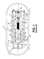
- the spring means includes a resonant spring having a first end portion affixed to the compressor assembly (generally to the actuating means) by a first fixation means, and a second end portion affixed to the non-resonant assembly, for example, to the cylinder block or to the supporting structure thereof, by a second fixation means, said fixation means including fixation portions retained to each other, generally by screws ( figure 1 ).
- Such retention presents some disadvantages, such as the possibility of gap formation and requirement of precise dimensioning.
- the dimensioning and the mounting of the parts defined by the piston, driving rod, actuating means and resonant spring should be made so that the piston be displaced to the nearest position in relation to the valve plate when in the upper dead point condition, i.e., in the compression stroke end condition, in order to make minimal the dead volume of refrigerant gas in the interior of the compression chamber and, thus, minimize the efficiency losses of the compressor.
- the distance between the piston top, when in the mounting position, and the valve plate should be such as to define adequate volumetric displacement and refrigeration capacity.
- the two following mounting conditions are fundamental for the correct functioning of the compressor: in the first place, the relative position of the piston top in relation to the cylinder top closed by the valve plate, in the mounting or resting condition of the piston, which condition will define the compressor capacity and variability; and, in the second place, the alignment of the piston in relation to the cylinder, which will define the loading on the (oil or pneumatic) bearing.
- the tolerances orthogonal to the main shaft of the compressor are required to be maintained in the same low levels. This implies high costs for manufacturing the components.
- the piston is coupled to the driving means to permit forces to be transferred therebetween and to make the piston be displaced in the interior of the compression chamber, according to an axial direction coincident with the axis of said compression chamber, in order to minimize the transversal reaction forces of the cylinder block against the piston in the interior of the compression chamber.
- Such transversal reaction forces of the cylinder block against the piston can provoke excessive friction between the piston and the cylinder block, leading: to an increase of energy consumption, with consequent reduction of the compressor efficiency; to an accelerated wear of the components submitted to the highest friction levels, reducing the useful life of the compressor; and to the presence of noise, due to friction.
- Another object of the present invention is to provide a mounting arrangement as cited above and which guarantees, upon mounting the piston to the cylinder, a desirable distance between the piston top and the cylinder top closed by the valve plate, and which results in an adequate capacity.
- a further object of the present invention is to provide a mounting arrangement as cited above, which presents a simple and low cost mounting between the parts defined by the piston and driving rod to the actuating means.
- the present invention provides an arrangement for mounting a resonant spring in a refrigeration compressor of the type which comprises, in the interior of a shell: a cylinder block defining a cylinder; a movable assembly formed by a piston reciprocating in the interior of the cylinder, an actuating means for driving the piston, and a driving rod coupling the piston to the actuating means; and a resonant spring having a first end portion affixed to the cylinder block by a first fixation means, and a second end portion affixed to the movable assembly by a second fixation means, in said mounting arrangement at least one of the first and second fixation means comprising a bearing portion which is attached, at a first side, to one of the end portions of the resonant spring and having, at an opposite side, a fixation face, and a bearing receiving portion, which is attached, at one side, to one of the parts of cylinder block and movable assembly, and having, at an opposite side,
- the resonant spring mounting arrangement of the present invention is carried out according to a mounting process which comprises the steps of: affixing a bearing portion of one of the first and second fixation means around one of the end portions of the resonant spring, said bearing portion having a fixation side and an opposite side with a fixation face; affixing a first side of a corresponding bearing receiving portion in one of the parts of cylinder block and movable assembly, said bearing receiving portion having a junction face opposite to the first side; and mutually seating and fusion welding the fixation and junction faces, which are deformed by mutual compression during the fusion welding, so as to attach the respective end portion of the resonant spring to one of the parts of movable assembly and cylinder block, maintaining said movable assembly concentric to the cylinder and in a predetermined axial positioning.
- the refrigeration compressor to which the resonant spring mounting arrangement of the present invention will be applied, comprises, in the interior of a generally hermetic shell 1, a cylinder block 2 in which is provided a cylinder 2a internally defining a compression chamber 2b, having an end 2c closed by a valve plate 3 and a head 4, and an open opposite end 2d through which is mounted a piston 5, which is operatively coupled to a linear electric motor M.
- the cylinder block 2 is mounted to the shell 1 through a suspension means 6, generally in the form of springs, such as helical springs of the illustrated type.
- the piston 5 is coupled to an actuating means 7 which carries magnets 8 energized by the electric motor M, through a driving rod 9.
- the piston 5, the driving rod 9 and the actuating means 7 (and magnets 8) define a movable assembly of the compressor.
- a resonant spring means 10 which is mounted in such a way as to exert opposite axial forces on the piston 5, upon its reciprocating axial displacement in the interior of the compression chamber 2b, provoked by a driving means which comprises the actuating means 7 and the magnets 8.
- the resonant spring means 10 operates as a guide for the axial displacement of the piston 5, making the movable assembly defined by the piston 5-driving rod 9-actuating means 7 actuate, allowing the linear electric motor M to be dimensioned to continuously supply energy to the compressor upon operation.
- the movable assembly and the resonant spring means 10 define a resonant assembly of the compressor.
- the resonant spring means 10 can present different constructions comprising one or more resonant springs 11.
- the resonant spring means 10 includes a resonant spring 11 having a first end portion 11a affixed to the non-resonant assembly, for example, to the cylinder block 2 or to the supporting structure thereof, by a first fixation means 20, and a second end portion 11b affixed to the movable assembly (generally to the actuating means 7) by a second fixation means 30.
- each end portion 11a, 11b, of the resonant spring 11 is disposed according to a direction orthogonal to the axis of the resonant spring 11.
- end portion 11a, 11b of a resonant spring 11 can be applied in different constructions of end portion 11a, 11b of a resonant spring 11, such as, for example, with at least one of said end portions 11a, 11b being parallel to said axis of the resonant spring 11.
- At least one of the first and second fixation means 20, 30 comprises a bearing portion 21, 31, previously attached, at a first side 21a, 31a, around one of the first and second end portions 11a, 11b of the resonant spring 11 and having, at an opposite side, a fixation face 21b, 31b, and a bearing receiving portion 22, 32, previously attached, at one side 22a, 32a, to one of the parts of cylinder block 2 and movable assembly, and having, at an opposite side, a junction face 22b, 32b.
- Said fixation face 21b, 31b and junction face 22b, 32b of the bearing portion 21, 31 and bearing receiving portion 22, 32 of said fixation means 20, 30 are seated and welded to each other, in order to secure the respective end portion 11a, 11b of the resonant spring 11 to one of the parts of movable assembly and cylinder block 2, maintaining said movable assembly concentric to the cylinder 2a and in a predetermined axial positioning.
- the fixation face 21b, 31b and junction face 22b, 32b of the bearing portion 21, 31 and bearing receiving portion 22, 32 of said fixation means 20, 30 are welded to each other by fusion, being deformed by mutual compression, during the fusion-welding process.
- the fixation by fusion can be obtained by heating one or both the fixation face 21b, 31b and junction face 22b, 32b, to be directly welded to each other, or said fusion can be obtained by disposing, between said fixation face 21b, 31b and junction face 22b, 32b, an additional element to be used in the hot or cold fusion of said parts.
- each end portion 11a, 11b, of the resonant spring 11 defines a circular section shaft portion which is tightly housed in the interior of a respective bearing portion of one of the first and second fixation means.
- the present invention is not limited to the profile of the resonant spring 11.
- the mounting arrangement presented herein can be also applied to end portions 11a, 11b of the resonant spring 11 presenting a profile different from the circular one described and illustrated herein.
- the mounting arrangement presented herein is carried out so as to allow the piston 5 to be concentrically mounted in the interior of the cylinder 2a, said concentricity being maintained during operation of the compressor, preventing impacts of the piston 5 against the inner surface of the cylinder 2a.
- the present mounting arrangement also permits adjusting the relative axial positioning of the piston 5 in relation to the top of cylinder 2a, which guarantees a previously calculated and desired volumetric displacement and refrigeration capacity to be reached during the operation of the compressor.
- the mounting arrangement of the present invention comprises only the second fixation means 30 having the respective bearing portion 31 disposed surrounding an adjacent end portion 11b of the resonant spring 11, the corresponding bearing receiving portion 32 being previously attached, surrounding an adjacent end of the actuating means 7, which is an extension of the driving rod 9.
- the bearing receiving portion 32 of the second fixation means 30 can be directly molded surrounding an adjacent end of the driving rod 9 or even of the piston 5, in the constructions in which the resonant spring means 10 is directly affixed to one of said parts.
- the mounting arrangement of the present invention further comprises the first fixation means 20, which has its bearing portion 21 provided surrounding an adjacent end portion 11a of the resonant spring 11 and the bearing receiving portion 22 being molded surrounding an adjacent surface portion of the cylinder block 2, although said bearing receiving portion 22 can be defined by an adjacent surface portion of the cylinder block 2, coaxial to the axis of the cylinder 2a.
- said adjacent surface portion of the cylinder block 2 is made of a material compatible with the welding to be applied thereto for fixation to an adjacent bearing portion 21 of the first fixation means 20.
- the first fixation means 20 has the bearing receiving portion 22 defining an end wall to the cylinder block 2, and being attached to an adjacent end thereof, for example, by screws.
- At least one of the parts of bearing portion 21, 31 and bearing receiving portion 22, 32 is molded directly on the respective part of the end portion 11a, 11b of the resonant spring 11, of the cylinder block 2 and of the movable assembly.
- each of said parts of bearing portion 31 and bearing receiving portion 32 is molded on the respective part of adjacent end portion 11b of the resonant spring 11 and adjacent end of the actuating means 7.
- each bearing portion 21, 31 and bearing receiving portion 22, 32 is over-injected on the respective part in which it is provided, said parts of bearing portion 21, 31 and bearing receiving portion 22, 32 being made, for example, of the same material and, more particularly, obtained in plastic material, for example, nylon.
- the bearing receiving portion 22 of the first fixation means 20 is defined by a portion of the cylinder block 2 attached to a portion thereof opposite to that in which the cylinder 2a is defined, said portion of the cylinder block 2 being in a material compatible with the fusion of the bearing portion 31, as already described, as well as in a plastic material, such as that of said bearing portion 21 of the first fixation means 20.
- the mounting arrangement of the present invention is obtained through a process for mounting the resonant spring 11 in a refrigeration compressor of the above-described-type, comprising the generic steps of: affixing a bearing portion 21, 31, of one of the first and second fixation means 20, 30 around one of the end portions 11a, 11b of the resonant spring 11, said bearing portion 21, 31 having a first side, for fixation to the end portion 11a, 11b of the resonant spring 11, and an opposite side with a fixation face 21b, 31b; affixing a first side of a corresponding bearing receiving portion 22, 32, to one of the parts of cylinder block 2 and movable assembly, said bearing receiving portion 22, 32 having a junction face 22a, 22b opposite to the first side; and mutually seating and welding the fixation face 21b, 31b and junction face 22b, 32b, so as to secure the respective end portion 11a, 11b of the resonant spring 11 to one of the parts of movable assembly and cylinder block 2, maintaining said movable assembly
- each bearing portion 21, 31 is carried out by molding, by over-injecting, each bearing portion 21, 31 on the part to which it will be simultaneously or sequentially attached.
- the bearing receiving portion 22 is also molded, by over-injection, to the movable assembly, particularly to an adjacent end of the actuating means 7, as already described.
- the present process generically and sequentially presents the additional steps of: heating at least one of the parts of fixation face 21b, 31b and junction face 22b, 32b of a bearing portion 21 and a bearing receiving portion 31 to be attached to each other; positioning said parts to each other, so as to obtain a coaxial positioning of the movable assembly in relation to the cylinder 2a; mutually seating said parts; and compressing said parts of fixation face 21b, 31b and junction face 22b, 32b, until obtaining a determined surface fusion thereof, corresponding to the predetermined axial positioning cited above.
- the movable assembly comprising the piston 5, the driving rod 9 and the actuating means 7 with the magnets 8 is positioned in an adequate device, as well as the resonant spring 11.
- the second fixation means 30 being already molded in the respective parts of movable assembly and resonant spring 11, there is initiated the heating of both the bearing portion 31 and the bearing receiving portion 32 of said second fixation means 30, until the respective fixation face 31b and junction face 32b are softened by fusion.
- said fixation face 31b and junction face 32b are mutually seated and compressed, until obtaining the plastic welding thereof.
- the two parts are positioned in a mounting device which guarantees the final position of the piston and its alignment in relation to the axis of the cylinder 2a, after the end of the process of welding and mutual fixation of the bearing portion 31 to the respective bearing receiving portion 32 of the second fixation means 30, the movable assembly and the resonant spring 11 can be both mutually mounted in the compressor, with the parts of bearing portion 21 and bearing receiving portion 22 of the first fixation means 20 being submitted to heating until they are softened and fused, before being seated and compressed for obtaining the fixation, by fusion, between the respective fixation face 21b and junction face 22b.
- the present process comprises, after molding each bearing portion 21, 31 and bearing receiving portion 22, 32, on the respective part in which they are carried, the additional steps of: providing a heat source 40, such as, for example, a hot plate, between each bearing portion 21, 31 and respective bearing receiving portion 22, 32, before the heating of the respective fixation face 21b, 31b and junction face 22b, 32b; heating said fixation face 21b, 31b and junction face 22b, 32b through the heat transfer from the heat source 40 to said parts, until obtaining the fusion thereof, before they are mutually seated under axial compression, in order to obtain the welding between said parts in the desired relative axial positioning of the piston 5 in relation to the top of cylinder 2a.
- a heat source 40 such as, for example, a hot plate
- the heat source 40 can be in the form of a plate in a material compatible with the fusion to be carried out, and maintained between the parts to be fused, integrating the fixation means under mounting process with the fusion, or said plate can be mounted only to obtain the heating of the fixation and junction faces. Said plate is removed from the region between said parts, after they are heated, to permit the mutual hot seating, and the fusion, according to the embodiment illustrated in figures 5 and 5a .
- the process presented herein comprises, after molding each bearing portion 21, 31 and bearing receiving portion 22, 32, on the respective part that carries it, the additional steps of: providing the fixation element 50 between each bearing portion 31 and respective bearing receiving portion 32, before heating the respective fixation face 31b and junction face 32b; positioning said parts to each other, so as to obtain a coaxial positioning of the movable assembly in relation to the cylinder 2a; conducting said bearing portion 31 and respective bearing receiving portion 32 to the mutual seating; heating said fixation face 31b and junction face 32b, until obtaining the fusion thereof around the fixation element 50 and to each other, so as to obtain the predetermined axial positioning between the parts of cylinder and piston.
- the heating can be carried out, for example, with the application of an induction field in the mutual seating region between the fixation face 31b and junction face 32b of the bearing portion 31 and bearing receiving portion 32.
- the fixation element 50 can be in the form of a pin (flat or provided with superficial grooves, preferably circumferential) made of a material whose fusion point is much superior to that of the parts of bearing portion 31 and bearing receiving portion 32 to be attached to each other, so that it can be axially maintained between the parts to be fused, actuating as a mechanical anchoring element for the fixation means under a fusion mounting process.
- the fixation element 50 can also actuate, before the fusion of the bearing portion 31 and bearing receiving portion 32, as a mounting guide element between said parts.
- each one of the fixation face 31b and junction face 32b of the bearing portion 31 and bearing receiving portion 32 is provided with a respective recess 31c, 32c, of calculated height, in a way in which gaps between the fixation element 50 and said bearing portion 31 and bearing receiving portion 32 are filled with the fusion of the fixation face 31b and junction face 32b.
- the fixation element 50 is provided in a high thermal conductibility material, for example metal, which, when heated, emanates heat and also heats the bearing portion 31 and bearing receiving portion 32, in the region of the fixation face 31b and junction face 32b, resulting in the fusion thereof.
- a high thermal conductibility material for example metal
- the fixation element 50 generically actuates as the heat source 40 already described.
- the heat source internal to the fixation means presenting its bearing portion 31 and bearing receiving portion 32, is heated by another heat source, external to said bearing portion 31 and bearing receiving portion 32.
- the processing steps already described for the fixation using the heat source 40 are also valid for this construction presenting the fixation element 50.
- the fixation element 50 remains housed between the recesses 31c, 32c, exerting the function of a mechanical anchorage element of the parts fused to each other.
- fixation process described herein is carried out in an adequate mounting device, which guarantees the correct positioning between the parts.
- the mounting arrangement of the present invention does not require very precise tolerances of the components to be mounted to each other, both in the direction of the axis of the cylinder block 2 and in the direction orthogonal to said axis, without compromising the concentric positioning of the movable assembly in relation to the axis of the cylinder, as well as in relation to the distance between a piston top portion in relation to the valve plate and which defines the volume displaced and the corresponding refrigeration capacity of the compressor.
Landscapes
- Engineering & Computer Science (AREA)
- Mechanical Engineering (AREA)
- General Engineering & Computer Science (AREA)
- Compressor (AREA)
- Compressors, Vaccum Pumps And Other Relevant Systems (AREA)
- Lining Or Joining Of Plastics Or The Like (AREA)
Applications Claiming Priority (2)
| Application Number | Priority Date | Filing Date | Title |
|---|---|---|---|
| BRPI0705541-2A BRPI0705541A2 (pt) | 2007-12-18 | 2007-12-18 | arranjo e processo de montagem de mola ressonante em compressor de refrigeração |
| PCT/BR2008/000364 WO2009076734A1 (en) | 2007-12-18 | 2008-12-03 | Arrangement and process for mounting a resonant spring in a refrigeration compressor |
Publications (2)
| Publication Number | Publication Date |
|---|---|
| EP2229533A1 EP2229533A1 (en) | 2010-09-22 |
| EP2229533B1 true EP2229533B1 (en) | 2013-02-13 |
Family
ID=40475067
Family Applications (1)
| Application Number | Title | Priority Date | Filing Date |
|---|---|---|---|
| EP08863233A Not-in-force EP2229533B1 (en) | 2007-12-18 | 2008-12-03 | Arrangement and process for mounting a resonant spring in a refrigeration compressor |
Country Status (8)
| Country | Link |
|---|---|
| US (1) | US8360749B2 (pt) |
| EP (1) | EP2229533B1 (pt) |
| JP (1) | JP5487115B2 (pt) |
| KR (1) | KR20100092501A (pt) |
| CN (1) | CN101903657B (pt) |
| BR (1) | BRPI0705541A2 (pt) |
| ES (1) | ES2400317T3 (pt) |
| WO (1) | WO2009076734A1 (pt) |
Families Citing this family (17)
| Publication number | Priority date | Publication date | Assignee | Title |
|---|---|---|---|---|
| BRPI1000181B1 (pt) * | 2010-01-05 | 2020-07-28 | Embraco Indústria De Compressores E Soluções E Refrigeração Ltda | arranjo de montagem de mola ressonante em um compressor de motor linear |
| BRPI1103647A2 (pt) * | 2011-07-07 | 2013-07-02 | Whirlpool Sa | disposiÇço entre componentes de compressor linear |
| BRPI1103447A2 (pt) * | 2011-07-19 | 2013-07-09 | Whirlpool Sa | feixe de molas para compressor e compressor provido de feixe de molas |
| BRPI1104172A2 (pt) * | 2011-08-31 | 2015-10-13 | Whirlpool Sa | compressor linear baseado em mecanismo oscilatório ressonante |
| BRPI1105017B1 (pt) * | 2011-11-25 | 2020-06-16 | Embraco Indústria De Compressores E Soluções E Refrigeração Ltda. | Dispositivo de controle de deformação de mola ressonante em uma unidade de acionamento linear |
| BR102012033619A2 (pt) * | 2012-12-28 | 2014-09-02 | Whirlpool Sa | Arranjo e processo de montagem de mola ressonante em um compressor de motor linear e compressor de motor linear |
| CN103170840B (zh) * | 2013-03-29 | 2016-04-06 | 浙江华尔士自控仪表阀门有限公司 | 一种弹簧缸装配工艺 |
| US9528505B2 (en) * | 2014-02-10 | 2016-12-27 | Haier Us Appliance Solutions, Inc. | Linear compressor |
| US9562525B2 (en) * | 2014-02-10 | 2017-02-07 | Haier Us Appliance Solutions, Inc. | Linear compressor |
| CN104454469B (zh) * | 2014-12-08 | 2016-07-06 | 珠海格力节能环保制冷技术研究中心有限公司 | 一种直线压缩机运动组件的装配装置和方法 |
| CN105626482A (zh) * | 2016-03-01 | 2016-06-01 | 珠海格力节能环保制冷技术研究中心有限公司 | 活塞组件及具有其的压缩机 |
| CN106246504B (zh) * | 2016-09-12 | 2018-09-28 | 珠海格力电器股份有限公司 | 直线压缩机 |
| KR102088316B1 (ko) * | 2018-08-28 | 2020-03-12 | 엘지전자 주식회사 | 리니어 압축기 |
| KR102157883B1 (ko) | 2018-07-17 | 2020-09-21 | 엘지전자 주식회사 | 리니어 압축기 |
| CN110725786B (zh) * | 2018-07-17 | 2021-11-30 | Lg电子株式会社 | 线性压缩机 |
| KR102285873B1 (ko) | 2019-04-03 | 2021-08-05 | 엘지전자 주식회사 | 리니어 압축기 |
| DE202020105191U1 (de) | 2020-09-09 | 2021-12-13 | topometric GmbH | Vorrichtung zur Positionierung eines beweglichen Bauteils relativ zu einem stationären Bauteil |
Family Cites Families (14)
| Publication number | Priority date | Publication date | Assignee | Title |
|---|---|---|---|---|
| US1390948A (en) * | 1920-10-02 | 1921-09-13 | Norman C Woodward | Spring-tire |
| IL100371A0 (en) * | 1991-01-11 | 1992-09-06 | Hughes Aircraft Co | Low cost electromagnetic linear actuator |
| IL109267A (en) * | 1993-04-13 | 1998-02-22 | Hughes Aircraft Co | Linear compressor including reciprocating piston and machined double-helix piston spring |
| JPH1026182A (ja) * | 1996-07-10 | 1998-01-27 | Exedy Corp | コイルスプリング組立体及びダンパー機構 |
| BR9900330A (pt) * | 1998-01-12 | 2000-03-28 | Lg Eletronics Inc | Estrutura para acoplamento de silenciador para compressor linear. |
| NZ500681A (en) * | 1999-10-21 | 2002-06-28 | Fisher & Paykel Appliances Ltd | A linear compressor with gas bearing passages between cylinder and cylinder lining |
| DE60135680D1 (en) * | 2001-05-25 | 2008-10-16 | Lg Electronics Inc | Kolbenverdichter |
| KR100529933B1 (ko) * | 2004-01-06 | 2005-11-22 | 엘지전자 주식회사 | 리니어 압축기 |
| KR100556800B1 (ko) * | 2004-03-25 | 2006-03-10 | 엘지전자 주식회사 | 왕복동식 압축기의 내측고정자 고정장치 |
| JP2006144568A (ja) * | 2004-11-16 | 2006-06-08 | Fuji Electric Holdings Co Ltd | 振動型圧縮機 |
| KR100680205B1 (ko) * | 2005-01-07 | 2007-02-08 | 엘지전자 주식회사 | 리니어 압축기 |
| US7722335B2 (en) * | 2005-05-06 | 2010-05-25 | Lg Electronics Inc. | Linear compressor |
| NZ541408A (en) * | 2005-07-21 | 2007-02-23 | Fisher & Paykel Appliances Ltd | Taper fit mounting of stator in free piston compressor motor |
| CN100559027C (zh) * | 2005-07-21 | 2009-11-11 | 菲舍尔和佩克尔应用有限公司 | 线性压缩机气缸和盖结构 |
-
2007
- 2007-12-18 BR BRPI0705541-2A patent/BRPI0705541A2/pt not_active IP Right Cessation
-
2008
- 2008-12-03 EP EP08863233A patent/EP2229533B1/en not_active Not-in-force
- 2008-12-03 KR KR1020107015093A patent/KR20100092501A/ko not_active Ceased
- 2008-12-03 JP JP2010538284A patent/JP5487115B2/ja not_active Expired - Fee Related
- 2008-12-03 CN CN200880121638.3A patent/CN101903657B/zh not_active Expired - Fee Related
- 2008-12-03 ES ES08863233T patent/ES2400317T3/es active Active
- 2008-12-03 WO PCT/BR2008/000364 patent/WO2009076734A1/en not_active Ceased
- 2008-12-08 US US12/809,121 patent/US8360749B2/en not_active Expired - Fee Related
Also Published As
| Publication number | Publication date |
|---|---|
| US20100310396A1 (en) | 2010-12-09 |
| JP5487115B2 (ja) | 2014-05-07 |
| ES2400317T3 (es) | 2013-04-09 |
| WO2009076734A1 (en) | 2009-06-25 |
| BRPI0705541A2 (pt) | 2009-08-18 |
| KR20100092501A (ko) | 2010-08-20 |
| CN101903657B (zh) | 2012-12-19 |
| CN101903657A (zh) | 2010-12-01 |
| JP2011508844A (ja) | 2011-03-17 |
| US8360749B2 (en) | 2013-01-29 |
| EP2229533A1 (en) | 2010-09-22 |
Similar Documents
| Publication | Publication Date | Title |
|---|---|---|
| US8360749B2 (en) | Arrangement and process for mounting a resonant spring in a refrigeration compressor | |
| CN102597473B (zh) | 自由活塞式斯特林机器的轴承支承系统 | |
| KR20120116461A (ko) | 공진 스프링을 선형 모터 압축기에 장착하는 장치 | |
| AU2004243788B2 (en) | Compressor improvements | |
| EP1488104B1 (en) | Reciprocating compressor driven by a linear motor | |
| EP1520106B1 (en) | Resonant arrangement for a linear compressor | |
| JP4406734B2 (ja) | 往復圧縮機用ツーピースコネクティングロッド及びツーピースコネクティングロッドを組み立てる方法 | |
| EP2385255A2 (en) | Hermetic compressor and manufacturing method thereof | |
| CN104968936B (zh) | 用来将共振弹簧安装在线性马达压缩机中的设备和方法以及线性马达压缩机 | |
| CN101523050B (zh) | 用于往复式压缩机的活塞-驱动杆装置 | |
| AU2013237743B2 (en) | Compressor improvements | |
| CN106930925B (zh) | 往复压缩机的两件式伸缩连接杆和组装杆的方法 | |
| EP4685349A1 (en) | Linear compressor with a linear electric motor and household appliance | |
| KR100851366B1 (ko) | 선형 모터를 구비한 왕복 압축기 | |
| KR20020035129A (ko) | 선형 모터가 구비된 왕복동식 압축기용 공진 조립체 | |
| NZ543828A (en) | Compressor improvements | |
| NZ555413A (en) | Compressor improvements |
Legal Events
| Date | Code | Title | Description |
|---|---|---|---|
| PUAI | Public reference made under article 153(3) epc to a published international application that has entered the european phase |
Free format text: ORIGINAL CODE: 0009012 |
|
| 17P | Request for examination filed |
Effective date: 20100602 |
|
| AK | Designated contracting states |
Kind code of ref document: A1 Designated state(s): AT BE BG CH CY CZ DE DK EE ES FI FR GB GR HR HU IE IS IT LI LT LU LV MC MT NL NO PL PT RO SE SI SK TR |
|
| AX | Request for extension of the european patent |
Extension state: AL BA MK RS |
|
| DAX | Request for extension of the european patent (deleted) | ||
| GRAP | Despatch of communication of intention to grant a patent |
Free format text: ORIGINAL CODE: EPIDOSNIGR1 |
|
| GRAS | Grant fee paid |
Free format text: ORIGINAL CODE: EPIDOSNIGR3 |
|
| GRAA | (expected) grant |
Free format text: ORIGINAL CODE: 0009210 |
|
| AK | Designated contracting states |
Kind code of ref document: B1 Designated state(s): AT BE BG CH CY CZ DE DK EE ES FI FR GB GR HR HU IE IS IT LI LT LU LV MC MT NL NO PL PT RO SE SI SK TR |
|
| REG | Reference to a national code |
Ref country code: GB Ref legal event code: FG4D |
|
| REG | Reference to a national code |
Ref country code: AT Ref legal event code: REF Ref document number: 596643 Country of ref document: AT Kind code of ref document: T Effective date: 20130215 |
|
| REG | Reference to a national code |
Ref country code: IE Ref legal event code: FG4D |
|
| REG | Reference to a national code |
Ref country code: DE Ref legal event code: R096 Ref document number: 602008022206 Country of ref document: DE Effective date: 20130404 |
|
| REG | Reference to a national code |
Ref country code: ES Ref legal event code: FG2A Ref document number: 2400317 Country of ref document: ES Kind code of ref document: T3 Effective date: 20130409 |
|
| REG | Reference to a national code |
Ref country code: AT Ref legal event code: MK05 Ref document number: 596643 Country of ref document: AT Kind code of ref document: T Effective date: 20130213 |
|
| REG | Reference to a national code |
Ref country code: NL Ref legal event code: VDEP Effective date: 20130213 |
|
| REG | Reference to a national code |
Ref country code: LT Ref legal event code: MG4D |
|
| PG25 | Lapsed in a contracting state [announced via postgrant information from national office to epo] |
Ref country code: LT Free format text: LAPSE BECAUSE OF FAILURE TO SUBMIT A TRANSLATION OF THE DESCRIPTION OR TO PAY THE FEE WITHIN THE PRESCRIBED TIME-LIMIT Effective date: 20130213 Ref country code: BG Free format text: LAPSE BECAUSE OF FAILURE TO SUBMIT A TRANSLATION OF THE DESCRIPTION OR TO PAY THE FEE WITHIN THE PRESCRIBED TIME-LIMIT Effective date: 20130513 Ref country code: NO Free format text: LAPSE BECAUSE OF FAILURE TO SUBMIT A TRANSLATION OF THE DESCRIPTION OR TO PAY THE FEE WITHIN THE PRESCRIBED TIME-LIMIT Effective date: 20130513 Ref country code: SE Free format text: LAPSE BECAUSE OF FAILURE TO SUBMIT A TRANSLATION OF THE DESCRIPTION OR TO PAY THE FEE WITHIN THE PRESCRIBED TIME-LIMIT Effective date: 20130213 Ref country code: AT Free format text: LAPSE BECAUSE OF FAILURE TO SUBMIT A TRANSLATION OF THE DESCRIPTION OR TO PAY THE FEE WITHIN THE PRESCRIBED TIME-LIMIT Effective date: 20130213 Ref country code: IS Free format text: LAPSE BECAUSE OF FAILURE TO SUBMIT A TRANSLATION OF THE DESCRIPTION OR TO PAY THE FEE WITHIN THE PRESCRIBED TIME-LIMIT Effective date: 20130613 |
|
| PG25 | Lapsed in a contracting state [announced via postgrant information from national office to epo] |
Ref country code: SI Free format text: LAPSE BECAUSE OF FAILURE TO SUBMIT A TRANSLATION OF THE DESCRIPTION OR TO PAY THE FEE WITHIN THE PRESCRIBED TIME-LIMIT Effective date: 20130213 Ref country code: FI Free format text: LAPSE BECAUSE OF FAILURE TO SUBMIT A TRANSLATION OF THE DESCRIPTION OR TO PAY THE FEE WITHIN THE PRESCRIBED TIME-LIMIT Effective date: 20130213 Ref country code: LV Free format text: LAPSE BECAUSE OF FAILURE TO SUBMIT A TRANSLATION OF THE DESCRIPTION OR TO PAY THE FEE WITHIN THE PRESCRIBED TIME-LIMIT Effective date: 20130213 Ref country code: BE Free format text: LAPSE BECAUSE OF FAILURE TO SUBMIT A TRANSLATION OF THE DESCRIPTION OR TO PAY THE FEE WITHIN THE PRESCRIBED TIME-LIMIT Effective date: 20130213 Ref country code: PL Free format text: LAPSE BECAUSE OF FAILURE TO SUBMIT A TRANSLATION OF THE DESCRIPTION OR TO PAY THE FEE WITHIN THE PRESCRIBED TIME-LIMIT Effective date: 20130213 Ref country code: PT Free format text: LAPSE BECAUSE OF FAILURE TO SUBMIT A TRANSLATION OF THE DESCRIPTION OR TO PAY THE FEE WITHIN THE PRESCRIBED TIME-LIMIT Effective date: 20130613 |
|
| PG25 | Lapsed in a contracting state [announced via postgrant information from national office to epo] |
Ref country code: HR Free format text: LAPSE BECAUSE OF FAILURE TO SUBMIT A TRANSLATION OF THE DESCRIPTION OR TO PAY THE FEE WITHIN THE PRESCRIBED TIME-LIMIT Effective date: 20130213 |
|
| PG25 | Lapsed in a contracting state [announced via postgrant information from national office to epo] |
Ref country code: SK Free format text: LAPSE BECAUSE OF FAILURE TO SUBMIT A TRANSLATION OF THE DESCRIPTION OR TO PAY THE FEE WITHIN THE PRESCRIBED TIME-LIMIT Effective date: 20130213 Ref country code: CZ Free format text: LAPSE BECAUSE OF FAILURE TO SUBMIT A TRANSLATION OF THE DESCRIPTION OR TO PAY THE FEE WITHIN THE PRESCRIBED TIME-LIMIT Effective date: 20130213 Ref country code: NL Free format text: LAPSE BECAUSE OF FAILURE TO SUBMIT A TRANSLATION OF THE DESCRIPTION OR TO PAY THE FEE WITHIN THE PRESCRIBED TIME-LIMIT Effective date: 20130213 Ref country code: DK Free format text: LAPSE BECAUSE OF FAILURE TO SUBMIT A TRANSLATION OF THE DESCRIPTION OR TO PAY THE FEE WITHIN THE PRESCRIBED TIME-LIMIT Effective date: 20130213 Ref country code: RO Free format text: LAPSE BECAUSE OF FAILURE TO SUBMIT A TRANSLATION OF THE DESCRIPTION OR TO PAY THE FEE WITHIN THE PRESCRIBED TIME-LIMIT Effective date: 20130213 Ref country code: EE Free format text: LAPSE BECAUSE OF FAILURE TO SUBMIT A TRANSLATION OF THE DESCRIPTION OR TO PAY THE FEE WITHIN THE PRESCRIBED TIME-LIMIT Effective date: 20130213 |
|
| PLBE | No opposition filed within time limit |
Free format text: ORIGINAL CODE: 0009261 |
|
| STAA | Information on the status of an ep patent application or granted ep patent |
Free format text: STATUS: NO OPPOSITION FILED WITHIN TIME LIMIT |
|
| 26N | No opposition filed |
Effective date: 20131114 |
|
| REG | Reference to a national code |
Ref country code: DE Ref legal event code: R097 Ref document number: 602008022206 Country of ref document: DE Effective date: 20131114 |
|
| REG | Reference to a national code |
Ref country code: CH Ref legal event code: PL |
|
| GBPC | Gb: european patent ceased through non-payment of renewal fee |
Effective date: 20131203 |
|
| PG25 | Lapsed in a contracting state [announced via postgrant information from national office to epo] |
Ref country code: LU Free format text: LAPSE BECAUSE OF FAILURE TO SUBMIT A TRANSLATION OF THE DESCRIPTION OR TO PAY THE FEE WITHIN THE PRESCRIBED TIME-LIMIT Effective date: 20131203 Ref country code: MC Free format text: LAPSE BECAUSE OF FAILURE TO SUBMIT A TRANSLATION OF THE DESCRIPTION OR TO PAY THE FEE WITHIN THE PRESCRIBED TIME-LIMIT Effective date: 20130213 |
|
| REG | Reference to a national code |
Ref country code: IE Ref legal event code: MM4A |
|
| PG25 | Lapsed in a contracting state [announced via postgrant information from national office to epo] |
Ref country code: CH Free format text: LAPSE BECAUSE OF NON-PAYMENT OF DUE FEES Effective date: 20131231 Ref country code: LI Free format text: LAPSE BECAUSE OF NON-PAYMENT OF DUE FEES Effective date: 20131231 Ref country code: IE Free format text: LAPSE BECAUSE OF NON-PAYMENT OF DUE FEES Effective date: 20131203 |
|
| PG25 | Lapsed in a contracting state [announced via postgrant information from national office to epo] |
Ref country code: GB Free format text: LAPSE BECAUSE OF NON-PAYMENT OF DUE FEES Effective date: 20131203 |
|
| PGFP | Annual fee paid to national office [announced via postgrant information from national office to epo] |
Ref country code: DE Payment date: 20141211 Year of fee payment: 7 Ref country code: ES Payment date: 20141216 Year of fee payment: 7 |
|
| PGFP | Annual fee paid to national office [announced via postgrant information from national office to epo] |
Ref country code: IT Payment date: 20141217 Year of fee payment: 7 |
|
| PGFP | Annual fee paid to national office [announced via postgrant information from national office to epo] |
Ref country code: FR Payment date: 20141230 Year of fee payment: 7 |
|
| PG25 | Lapsed in a contracting state [announced via postgrant information from national office to epo] |
Ref country code: CY Free format text: LAPSE BECAUSE OF FAILURE TO SUBMIT A TRANSLATION OF THE DESCRIPTION OR TO PAY THE FEE WITHIN THE PRESCRIBED TIME-LIMIT Effective date: 20130213 Ref country code: TR Free format text: LAPSE BECAUSE OF FAILURE TO SUBMIT A TRANSLATION OF THE DESCRIPTION OR TO PAY THE FEE WITHIN THE PRESCRIBED TIME-LIMIT Effective date: 20130213 |
|
| PG25 | Lapsed in a contracting state [announced via postgrant information from national office to epo] |
Ref country code: HU Free format text: LAPSE BECAUSE OF FAILURE TO SUBMIT A TRANSLATION OF THE DESCRIPTION OR TO PAY THE FEE WITHIN THE PRESCRIBED TIME-LIMIT; INVALID AB INITIO Effective date: 20081203 |
|
| PG25 | Lapsed in a contracting state [announced via postgrant information from national office to epo] |
Ref country code: MT Free format text: LAPSE BECAUSE OF FAILURE TO SUBMIT A TRANSLATION OF THE DESCRIPTION OR TO PAY THE FEE WITHIN THE PRESCRIBED TIME-LIMIT Effective date: 20130213 Ref country code: GR Free format text: LAPSE BECAUSE OF NON-PAYMENT OF DUE FEES Effective date: 20130213 |
|
| REG | Reference to a national code |
Ref country code: DE Ref legal event code: R119 Ref document number: 602008022206 Country of ref document: DE |
|
| REG | Reference to a national code |
Ref country code: FR Ref legal event code: ST Effective date: 20160831 |
|
| PG25 | Lapsed in a contracting state [announced via postgrant information from national office to epo] |
Ref country code: DE Free format text: LAPSE BECAUSE OF NON-PAYMENT OF DUE FEES Effective date: 20160701 |
|
| PG25 | Lapsed in a contracting state [announced via postgrant information from national office to epo] |
Ref country code: FR Free format text: LAPSE BECAUSE OF NON-PAYMENT OF DUE FEES Effective date: 20151231 |
|
| PG25 | Lapsed in a contracting state [announced via postgrant information from national office to epo] |
Ref country code: IT Free format text: LAPSE BECAUSE OF NON-PAYMENT OF DUE FEES Effective date: 20151203 |
|
| REG | Reference to a national code |
Ref country code: ES Ref legal event code: FD2A Effective date: 20170405 |
|
| PG25 | Lapsed in a contracting state [announced via postgrant information from national office to epo] |
Ref country code: ES Free format text: LAPSE BECAUSE OF NON-PAYMENT OF DUE FEES Effective date: 20151204 |