EP2230113A1 - Dispositif destiné au conditionnement d'air d'un véhicule automobile - Google Patents
Dispositif destiné au conditionnement d'air d'un véhicule automobile Download PDFInfo
- Publication number
- EP2230113A1 EP2230113A1 EP10166322A EP10166322A EP2230113A1 EP 2230113 A1 EP2230113 A1 EP 2230113A1 EP 10166322 A EP10166322 A EP 10166322A EP 10166322 A EP10166322 A EP 10166322A EP 2230113 A1 EP2230113 A1 EP 2230113A1
- Authority
- EP
- European Patent Office
- Prior art keywords
- evaporator
- refrigerant
- ejector
- separating element
- evaporators
- Prior art date
- Legal status (The legal status is an assumption and is not a legal conclusion. Google has not performed a legal analysis and makes no representation as to the accuracy of the status listed.)
- Granted
Links
Images


Classifications
-
- B—PERFORMING OPERATIONS; TRANSPORTING
- B60—VEHICLES IN GENERAL
- B60H—ARRANGEMENTS OF HEATING, COOLING, VENTILATING OR OTHER AIR-TREATING DEVICES SPECIALLY ADAPTED FOR PASSENGER OR GOODS SPACES OF VEHICLES
- B60H1/00—Heating, cooling or ventilating devices
- B60H1/32—Cooling devices
- B60H1/3204—Cooling devices using compression
- B60H1/3227—Cooling devices using compression characterised by the arrangement or the type of heat exchanger, e.g. condenser, evaporator
-
- B—PERFORMING OPERATIONS; TRANSPORTING
- B60—VEHICLES IN GENERAL
- B60H—ARRANGEMENTS OF HEATING, COOLING, VENTILATING OR OTHER AIR-TREATING DEVICES SPECIALLY ADAPTED FOR PASSENGER OR GOODS SPACES OF VEHICLES
- B60H1/00—Heating, cooling or ventilating devices
- B60H1/32—Cooling devices
- B60H1/3204—Cooling devices using compression
- B60H1/3205—Control means therefor
- B60H1/3211—Control means therefor for increasing the efficiency of a vehicle refrigeration cycle
-
- F—MECHANICAL ENGINEERING; LIGHTING; HEATING; WEAPONS; BLASTING
- F25—REFRIGERATION OR COOLING; COMBINED HEATING AND REFRIGERATION SYSTEMS; HEAT PUMP SYSTEMS; MANUFACTURE OR STORAGE OF ICE; LIQUEFACTION SOLIDIFICATION OF GASES
- F25B—REFRIGERATION MACHINES, PLANTS OR SYSTEMS; COMBINED HEATING AND REFRIGERATION SYSTEMS; HEAT PUMP SYSTEMS
- F25B41/00—Fluid-circulation arrangements
-
- B—PERFORMING OPERATIONS; TRANSPORTING
- B60—VEHICLES IN GENERAL
- B60H—ARRANGEMENTS OF HEATING, COOLING, VENTILATING OR OTHER AIR-TREATING DEVICES SPECIALLY ADAPTED FOR PASSENGER OR GOODS SPACES OF VEHICLES
- B60H1/00—Heating, cooling or ventilating devices
- B60H1/32—Cooling devices
- B60H2001/3286—Constructional features
- B60H2001/3297—Expansion means other than expansion valve
-
- B—PERFORMING OPERATIONS; TRANSPORTING
- B60—VEHICLES IN GENERAL
- B60H—ARRANGEMENTS OF HEATING, COOLING, VENTILATING OR OTHER AIR-TREATING DEVICES SPECIALLY ADAPTED FOR PASSENGER OR GOODS SPACES OF VEHICLES
- B60H1/00—Heating, cooling or ventilating devices
- B60H1/32—Cooling devices
- B60H2001/3286—Constructional features
- B60H2001/3298—Ejector-type refrigerant circuits
-
- F—MECHANICAL ENGINEERING; LIGHTING; HEATING; WEAPONS; BLASTING
- F25—REFRIGERATION OR COOLING; COMBINED HEATING AND REFRIGERATION SYSTEMS; HEAT PUMP SYSTEMS; MANUFACTURE OR STORAGE OF ICE; LIQUEFACTION SOLIDIFICATION OF GASES
- F25B—REFRIGERATION MACHINES, PLANTS OR SYSTEMS; COMBINED HEATING AND REFRIGERATION SYSTEMS; HEAT PUMP SYSTEMS
- F25B2341/00—Details of ejectors not being used as compression device; Details of flow restrictors or expansion valves
- F25B2341/001—Ejectors not being used as compression device
- F25B2341/0012—Ejectors with the cooled primary flow at high pressure
-
- F—MECHANICAL ENGINEERING; LIGHTING; HEATING; WEAPONS; BLASTING
- F25—REFRIGERATION OR COOLING; COMBINED HEATING AND REFRIGERATION SYSTEMS; HEAT PUMP SYSTEMS; MANUFACTURE OR STORAGE OF ICE; LIQUEFACTION SOLIDIFICATION OF GASES
- F25B—REFRIGERATION MACHINES, PLANTS OR SYSTEMS; COMBINED HEATING AND REFRIGERATION SYSTEMS; HEAT PUMP SYSTEMS
- F25B39/00—Evaporators; Condensers
- F25B39/02—Evaporators
-
- F—MECHANICAL ENGINEERING; LIGHTING; HEATING; WEAPONS; BLASTING
- F25—REFRIGERATION OR COOLING; COMBINED HEATING AND REFRIGERATION SYSTEMS; HEAT PUMP SYSTEMS; MANUFACTURE OR STORAGE OF ICE; LIQUEFACTION SOLIDIFICATION OF GASES
- F25B—REFRIGERATION MACHINES, PLANTS OR SYSTEMS; COMBINED HEATING AND REFRIGERATION SYSTEMS; HEAT PUMP SYSTEMS
- F25B5/00—Compression machines, plants or systems, with several evaporator circuits, e.g. for varying refrigerating capacity
- F25B5/04—Compression machines, plants or systems, with several evaporator circuits, e.g. for varying refrigerating capacity arranged in series
Definitions
- the invention relates to a device for air conditioning for a motor vehicle according to the preamble of claim 1.
- the EP 0 487 002 A2 describes an air conditioning system for a motor vehicle, in which an ejector is used to improve the efficiency.
- the refrigerant flow leaving a condenser expands in the ejector while absorbing speed, whereby a second refrigerant flow is sucked and mixed.
- the second stream comes from the single evaporator of the system and experiences a total pressure increase through the supply to the ejector.
- Central element for the function is also arranged downstream of the ejector phase separator, through which a liquid part is separated and fed to the evaporator, whereas a gaseous part of the refrigerant is supplied to the compressor.
- the suction pressure at the compressor is thereby at a higher level than the pressure of the refrigerant after the evaporator.
- the required for safe operation of the device complete separation of gaseous and liquid Phase requires a complex and much space-consuming phase separator.
- the arrangement of the lines is more expensive than in air conditioning systems according to the prior art.
- the DE 10 2005 021 396 describes an apparatus for air conditioning in which also an ejector is used to improve the efficiency.
- a second evaporator is additionally achieved that the part of the refrigerant after the ejector, which is supplied to the compressor, also a cooling capacity can be removed.
- Form assembly form or be arranged in the immediate vicinity of the first and / or second evaporator.
- the ejector may be located above or below the first and / or second evaporator depending on space requirements.
- the ejector can be arranged in the installed position in front of or behind the first and / or second evaporator.
- an arrangement is conceivable in which the ejector is horizontal, vertical or diagonal.
- the first and second evaporator are formed as a structural unit and in particular soldered or welded or joined together by another cohesive method.
- the second evaporator is arranged in the air flow direction in front of the first evaporator.
- the first and / or second evaporator is flowed through in multiple floods.
- Multi-flush in the sense of the invention means that an evaporator has at least two pipe groups or floods, which can be traversed by a refrigerant. In this case, adjacent flows are preferably flowed through in opposite directions.
- the individual floods consist of several tubes, in particular flat tubes. Preferably, between the tubes, ribs, in particular corrugated fins are arranged to improve the heat transfer between the fluid to be cooled, in particular air, and the refrigerant.
- the two evaporators are flowed through in the opposite direction in the direction perpendicular to the floods.
- the respective outputs of the two evaporators are located on different sides.
- a separating element is arranged downstream of the ejector.
- the separating element may be formed, for example, as a pipe branching, deflecting plate, fleece or grid.
- any other element is conceivable that divides the refrigerant flow into a first partial flow flowing to the first evaporator and into a second partial flow flowing to the second evaporator.
- the separation of the two partial flows can be carried out such that the first partial flow has a substantially equal or greater liquid content than the second partial flow.
- a third evaporator is arranged downstream of the second evaporator.
- the second evaporator with the third evaporator forms a structural unit.
- a second separating element in particular a phase-separating separating element, is arranged downstream of the first separating element and upstream of the first evaporator.
- the second separating element is communicatively connected to a line which connects the second and third evaporators communicating with each other.
- a collector and / or an internal heat exchanger is arranged downstream of the second or the third evaporator and upstream of the compressor.
- any overheating zone on the air outlet side evaporator (first evaporator) has a negative effect on a performance gain of the ejector.
- a method is proposed in which a flow value of a throttle element on the inflow side of the first evaporator is set in such a way that no overheating zone occurs at the first evaporator at all operating points.
- the flow rate here depends on the refrigerant used and whether upstream of the throttle element, a phase separation is provided or not.
- Such flowcharacteristics relate to a device for air conditioning of medium power class.
- Typical values of the flow index A for smaller and larger performance classes are in the range from 0.1 * A to 10 * A, preferably in a range from 0.5 * A to 2 * A.
- the flow index A of the throttle element is preferably not changed during operation and refers for example to a valve with orifice.
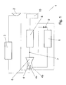
- Fig. 1 shows a schematic representation of a device for air conditioning 1 according to the prior art.
- a device for air conditioning 1 according to the prior art.
- Such a device consists of a compressor 2, which converts a refrigerant from an expanded to a compressed state.
- the compressor is followed by a heat exchanger 3, in particular a condenser, which dissipates the heat generated during the compression of the refrigerant to the environment.
- the heat exchanger is followed downstream by a designed as ejector 4 expansion element.
- the ejector has a nozzle 4 formed as a first input 4a for a refrigerant, in which the refrigerant is first expanded and accelerated in a highly directed beam.
- this jet mixes with refrigerant from a branching out of a first evaporator 5 into a second inlet 4b into the ejector.
- mechanical work of the directed, fast jet of the nozzle or of the first nozzle Input 4a used.
- the mixing of the two beams and the subsequent expansion of the directional mixed jet in a diffuser 6 of the ejector 4 lead to a pressure increase of the mixture.
- This mixture contains liquid and gaseous phase of the refrigerant.
- the refrigerant After leaving the ejector, the refrigerant enters a separating element 7.
- the first evaporator 5 is charged with a part of the entering into the separator 7 refrigerant.
- the remaining portion is fed to a second evaporator 8.
- a cooling capacity of the entire system is produced by evaporation of the liquid portions and corresponding heat exchange with air to be air-conditioned.
- the proportion of liquid refrigerant in the two partial streams may be the same or different, wherein an enrichment of the liquid phase of the partial flow to the first evaporator 5 is advantageous.
- the second evaporator 8 is followed by a low-pressure accumulator 10, which in turn follows the suction side of the compressor 2.
- an expansion element 9 is arranged, in which the refrigerant is expanded to a low evaporation pressure.
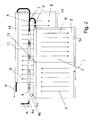
- a first embodiment of a device according to the invention for air conditioning is shown schematically.
- This embodiment differs from the prior art in particular in that the ejector 4 is arranged adjacent to the first evaporator 5.
- any arrangement of the ejector is conceivable, wherein the ejector in Fig. 2 is shown only schematically and may have any configuration according to the prior art.
- the ejector may be arranged above or below the first or second evaporator.
- the first and second evaporator and the ejector form a structural unit.
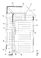
- the first and second evaporators each have an upper and lower collecting duct 14 and partitions 11, so that the two evaporators are flowed through in several flutes with refrigerant (indicated by arrows K).
- the two evaporators are flown with air to be cooled (indicated by arrow L), wherein the second evaporator 8 is arranged in the air flow direction in front of the first evaporator 5.
- the device has a separating element 7 which separates the refrigerant flow into a first partial stream flowing to the first evaporator 5 and a second partial stream flowing to the second evaporator 8.
- the separation of the two streams to the two evaporators can be such that no significant differences in the liquid content arise or that the liquid content of the first partial stream is greater than the liquid content of the second partial stream.
- the separation takes place in the simplest case by a branch pipe or, for example, by a vertical guide plate, as long as the refrigerant flow still flows along the main axis of the ejector.
- phase-separating elements such as baffles, nonwovens, mesh or other packings may be arranged.
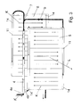
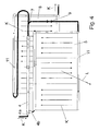
- Fig. 3 and Fig. 4 show two further embodiments of a device according to the invention for air conditioning.
- the two evaporators are flowed through in three floods.
- a flow through the evaporator in four, five, six or any other number of floods possible, the two evaporators may each have an equal or different number of floods.
- Flows of the first and second evaporators, which are arranged one behind the other in the direction of air flow, are flowed through in opposite directions. additionally the refrigerant outlets are arranged on different sides.
- Such an arrangement has the advantage that thus overheating zones which form in the region of the refrigerant outlets of the evaporator, occur on different sides of the evaporator, so that their influence on the temperature profile of the air to be cooled is not reinforced, but partially or completely canceled ,
- Fig. 5 shows in particular a further embodiment of a separating element 7.
- the separated liquid collects in the lower region of the separating element and is supplied from there via the expansion element 9 to the first evaporator 5.
- the end of the suction duct 13 may be mounted geodetically lower, so that in the event that more liquid is deposited than flows through the expansion element 9, the remaining part of the liquid can flow into the second evaporator 8, before the large volume of the separating element is filled.
- Fig. 6 shows in particular a further embodiment of a separating element 7.
- the Kältternittelansaugung the second evaporator 8 is in this case geodetically higher than that of the first evaporator 5, so that in the first evaporator always preferred liquid refrigerant flows.
- the end of the suction line 13 may be designed such that liquid is not suddenly sucked into the second evaporator 8.
- the end of the suction line may be slotted or have a plurality of inlet bores.
- a plurality of suction lines 12 at different Be provided points of the separating element 7.
- Several intake pipes can also be used in the embodiments according to FIG Fig. 5 .
- Fig. 10 and Fig. 11 be attached to different locations of the separating element 7.
- the separating element 7 internals, such as sheets, which prevent sloshing of the liquid.
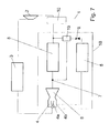
- Fig. 7 shows a further embodiment of a device according to the invention.
- This device has a second separating element 19, in particular a phase-separating separating element.
- the first separating element 7 may be formed as a pipe branch, so that the first and second partial stream downstream of the first separating element 7 may essentially have an equal liquid content.
- the second separating element 19 is communicatively connected to a line which communicates the second evaporator 8 downstream with the low-pressure accumulator 10, so that the vapor deposited in the second separating element 19 is fed downstream of the second evaporator 8.
- Such an arrangement has the advantage that the second separating element 19 can be operated with a pressure drop in the same size as in the second evaporator 8.
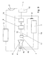
- a third evaporator 15 is arranged downstream of the second evaporator 8.
- the second phase-separating separator 19 is communicatively connected to a line communicatively connecting the second and third evaporators.
- the phase-separating separator 19 can thus with a Pressure drop according to the second evaporator 8 are operated.
- the first phase-separating separator 7 is communicatively connected by a conduit 17 to a conduit communicatively connecting the second and third evaporators. In this case, it is possible to dispense with the second separating element 19.
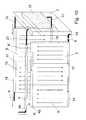
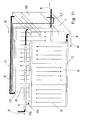
- Fig. 10 shows a further embodiment, or a concretization of the embodiment according to Fig. 9 , in which the second 8 and third 15 evaporator form a structural unit, so that a compact and space-saving design is possible.
- the phase-separating first separating element 7 in this case has a dense packing made of fleece or other phase-separating packs 16.
- the line 17 opens into the lower collecting channel 14 of the second evaporator eighth
- the second evaporator 8 can also be designed as a pipeline to the third evaporator 15.
- Such an embodiment, which in Fig. 11 is shown is particularly advantageous if constructive conditions already result in a significant pressure drop of such a line between the separator 7 and the third evaporator 15.
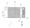
- Fig. 12 shows a detailed view of a first separation element 7 according to the invention with the corresponding supply lines and leads, which in Fig. 10 are shown. It will be readily apparent to those skilled in the art that primarily liquid will be drawn through the conduit 19 into the first evaporator 5 because the end of the conduit 17 is above the liquid level 21.
- both the ejector and the first, second and third evaporator, the expansion element 9 and the first and / or second separating element may be formed into a structural unit 18.
- the device according to the invention is not limited to a specific refrigerant.
- the device in addition to the refrigerant R134a, the device is also suitable for the refrigerant R744.
- the device comprises an internal heat exchanger, which further improves the efficiency.
Landscapes
- Engineering & Computer Science (AREA)
- Physics & Mathematics (AREA)
- Thermal Sciences (AREA)
- Mechanical Engineering (AREA)
- General Engineering & Computer Science (AREA)
- Air-Conditioning For Vehicles (AREA)
- Jet Pumps And Other Pumps (AREA)
Applications Claiming Priority (2)
| Application Number | Priority Date | Filing Date | Title |
|---|---|---|---|
| DE102007049823 | 2007-10-16 | ||
| EP08018143A EP2050601B1 (fr) | 2007-10-16 | 2008-10-16 | Dispositif destiné au conditionnement d'air d'un véhicule automobile |
Related Parent Applications (1)
| Application Number | Title | Priority Date | Filing Date |
|---|---|---|---|
| EP08018143.1 Division | 2008-10-16 |
Publications (2)
| Publication Number | Publication Date |
|---|---|
| EP2230113A1 true EP2230113A1 (fr) | 2010-09-22 |
| EP2230113B1 EP2230113B1 (fr) | 2011-10-12 |
Family
ID=40244691
Family Applications (3)
| Application Number | Title | Priority Date | Filing Date |
|---|---|---|---|
| EP10166312A Ceased EP2223815B1 (fr) | 2007-10-16 | 2008-10-16 | Dispositif destiné au conditionnement d'air d'un véhicule automobile |
| EP10166322A Ceased EP2230113B1 (fr) | 2007-10-16 | 2008-10-16 | Dispositif destiné au conditionnement d'air d'un véhicule automobile |
| EP08018143A Ceased EP2050601B1 (fr) | 2007-10-16 | 2008-10-16 | Dispositif destiné au conditionnement d'air d'un véhicule automobile |
Family Applications Before (1)
| Application Number | Title | Priority Date | Filing Date |
|---|---|---|---|
| EP10166312A Ceased EP2223815B1 (fr) | 2007-10-16 | 2008-10-16 | Dispositif destiné au conditionnement d'air d'un véhicule automobile |
Family Applications After (1)
| Application Number | Title | Priority Date | Filing Date |
|---|---|---|---|
| EP08018143A Ceased EP2050601B1 (fr) | 2007-10-16 | 2008-10-16 | Dispositif destiné au conditionnement d'air d'un véhicule automobile |
Country Status (2)
| Country | Link |
|---|---|
| EP (3) | EP2223815B1 (fr) |
| DE (2) | DE502008002371D1 (fr) |
Cited By (1)
| Publication number | Priority date | Publication date | Assignee | Title |
|---|---|---|---|---|
| JP2012106574A (ja) * | 2010-11-16 | 2012-06-07 | Tgk Co Ltd | 車両用冷暖房装置に用いられる制御弁 |
Families Citing this family (5)
| Publication number | Priority date | Publication date | Assignee | Title |
|---|---|---|---|---|
| DE102009050886A1 (de) * | 2009-10-27 | 2011-04-28 | Behr Gmbh & Co. Kg | Verdampfermodul |
| DE102010031388A1 (de) | 2010-07-15 | 2012-01-19 | Behr Gmbh & Co. Kg | Expansionselement für ein System zur Luftkonditionierung für ein Kraftfahrzeug |
| DE102010031391A1 (de) | 2010-07-15 | 2012-01-19 | Behr Gmbh & Co. Kg | Verdampfermodul |
| DE102013100457A1 (de) * | 2013-01-17 | 2014-07-17 | Dr. Ing. H.C. F. Porsche Aktiengesellschaft | Kältemittelführendes Leitungselement |
| CN107074072B (zh) * | 2015-06-30 | 2019-06-25 | 翰昂汽车零部件有限公司 | 室外热交换器 |
Citations (5)
| Publication number | Priority date | Publication date | Assignee | Title |
|---|---|---|---|---|
| EP0487002A2 (fr) * | 1990-11-19 | 1992-05-27 | THERMAL-WERKE Wärme-, Kälte-, Klimatechnik GmbH | Dispositif de climatisation de l'habitacle d'un véhicule automobile |
| EP1327838A2 (fr) * | 2002-01-15 | 2003-07-16 | Denso Corporation | Appareil de conditionnement d'air avec système à cycle d'éjection |
| DE102006014867A1 (de) * | 2005-04-01 | 2006-10-05 | Denso Corp., Kariya | Ejektorpumpenkühlkreis |
| EP1719650A1 (fr) * | 2005-05-04 | 2006-11-08 | Behr GmbH & Co. KG | Climatisation pour véhicule |
| DE102006011327A1 (de) * | 2006-03-09 | 2007-09-13 | Behr Gmbh & Co. Kg | Wärmeübertrager mit Kältespeicher |
Family Cites Families (2)
| Publication number | Priority date | Publication date | Assignee | Title |
|---|---|---|---|---|
| JP4595607B2 (ja) * | 2005-03-18 | 2010-12-08 | 株式会社デンソー | エジェクタを使用した冷凍サイクル |
| US20060254308A1 (en) * | 2005-05-16 | 2006-11-16 | Denso Corporation | Ejector cycle device |
-
2008
- 2008-10-16 DE DE502008002371T patent/DE502008002371D1/de active Active
- 2008-10-16 DE DE102008051892A patent/DE102008051892A1/de not_active Withdrawn
- 2008-10-16 EP EP10166312A patent/EP2223815B1/fr not_active Ceased
- 2008-10-16 EP EP10166322A patent/EP2230113B1/fr not_active Ceased
- 2008-10-16 EP EP08018143A patent/EP2050601B1/fr not_active Ceased
Patent Citations (5)
| Publication number | Priority date | Publication date | Assignee | Title |
|---|---|---|---|---|
| EP0487002A2 (fr) * | 1990-11-19 | 1992-05-27 | THERMAL-WERKE Wärme-, Kälte-, Klimatechnik GmbH | Dispositif de climatisation de l'habitacle d'un véhicule automobile |
| EP1327838A2 (fr) * | 2002-01-15 | 2003-07-16 | Denso Corporation | Appareil de conditionnement d'air avec système à cycle d'éjection |
| DE102006014867A1 (de) * | 2005-04-01 | 2006-10-05 | Denso Corp., Kariya | Ejektorpumpenkühlkreis |
| EP1719650A1 (fr) * | 2005-05-04 | 2006-11-08 | Behr GmbH & Co. KG | Climatisation pour véhicule |
| DE102006011327A1 (de) * | 2006-03-09 | 2007-09-13 | Behr Gmbh & Co. Kg | Wärmeübertrager mit Kältespeicher |
Cited By (1)
| Publication number | Priority date | Publication date | Assignee | Title |
|---|---|---|---|---|
| JP2012106574A (ja) * | 2010-11-16 | 2012-06-07 | Tgk Co Ltd | 車両用冷暖房装置に用いられる制御弁 |
Also Published As
| Publication number | Publication date |
|---|---|
| EP2050601A3 (fr) | 2009-05-06 |
| EP2223815A1 (fr) | 2010-09-01 |
| EP2050601B1 (fr) | 2011-01-19 |
| DE102008051892A1 (de) | 2009-05-20 |
| EP2230113B1 (fr) | 2011-10-12 |
| EP2050601A2 (fr) | 2009-04-22 |
| EP2223815B1 (fr) | 2011-10-12 |
| DE502008002371D1 (de) | 2011-03-03 |
Similar Documents
| Publication | Publication Date | Title |
|---|---|---|
| EP2050601B1 (fr) | Dispositif destiné au conditionnement d'air d'un véhicule automobile | |
| DE102005038858B4 (de) | Dampfkompressionskreis mit Ejektorpumpe | |
| EP0019057A1 (fr) | Epurateur de poussière du type à tourbillonnement à plusieurs étages | |
| EP1719650B1 (fr) | Climatisation pour véhicule | |
| DE3028304A1 (de) | Waermeaustauscher | |
| DE102008005077B4 (de) | Plattenverdampfer, insbesondere für einen Kältemittelkreis | |
| DE102017211256A1 (de) | Kälteanlage für ein Fahrzeug mit einem einen Wärmeübertrager aufweisenden Kältemittelkreislauf sowie Wärmeübertrager für eine solche Kälteanlage | |
| DE102011013340A1 (de) | Verteileinrichtung und Wärmetauschervorrichtung | |
| DE102015211606B4 (de) | Verdampfereinheit für eine Aufdachklimaanlage eines Straßenfahrzeugs sowie Aufdachklimaanlage mit Verdampfereinheit | |
| EP2135025B1 (fr) | Échangeur de chaleur pour la vaporisation d'une partie liquide d'un milieu, pourvu d'une dérivation pour une partie à l'état de vapeur du milieu | |
| DE102017211736A1 (de) | Kondensator | |
| DE102005062423A1 (de) | Verdampfapparat | |
| DE112015000750T5 (de) | Kältefluidkreislauf zur thermischen Behandlung eines Kraftfahrzeugs | |
| EP2757340A2 (fr) | Refroidisseur | |
| DE102015204984A1 (de) | Wärmetauscher, insbesondere für eine Abwärmenutzungseinrichtung | |
| DE10322165B4 (de) | Kältemittel-Kühlwärmetauscher | |
| DE102021213376A1 (de) | Wärmeübertrager und Kältemittelkreislauf mit einem Wärmeübertrager | |
| DE102022201204A1 (de) | Wärmeübertragermodul | |
| DE102014209452A1 (de) | Klimaanlage mit Bypassvorrichtung | |
| EP2316674B1 (fr) | Module d'évaporateur | |
| DE102005059917A1 (de) | Verdampfer | |
| WO2019015891A1 (fr) | Dispositif de réfrigération comportant un circuit de réfrigération | |
| DE102013100884A1 (de) | Interner Wärmetauscher mit Trocknungsmittel | |
| DE102018213835B4 (de) | Fahrzeug mit einem Kältemittelkreis | |
| DE102024115725A1 (de) | Motormodul |
Legal Events
| Date | Code | Title | Description |
|---|---|---|---|
| PUAI | Public reference made under article 153(3) epc to a published international application that has entered the european phase |
Free format text: ORIGINAL CODE: 0009012 |
|
| AC | Divisional application: reference to earlier application |
Ref document number: 2050601 Country of ref document: EP Kind code of ref document: P |
|
| AK | Designated contracting states |
Kind code of ref document: A1 Designated state(s): DE FR GB |
|
| RIN1 | Information on inventor provided before grant (corrected) |
Inventor name: WALTER, CHRISTOPH Inventor name: DUERR, GOTTFRIED Inventor name: FEUERECKER, GUENTHER Inventor name: KEMLE, ANDREAS |
|
| 17P | Request for examination filed |
Effective date: 20110322 |
|
| GRAP | Despatch of communication of intention to grant a patent |
Free format text: ORIGINAL CODE: EPIDOSNIGR1 |
|
| RIC1 | Information provided on ipc code assigned before grant |
Ipc: B60H 1/32 20060101AFI20110428BHEP |
|
| RIN1 | Information on inventor provided before grant (corrected) |
Inventor name: FEUERECKER, GUENTHER Inventor name: WALTER, CHRISTOPH Inventor name: KEMLE, ANDREAS Inventor name: DUERR, GOTTFRIED |
|
| GRAS | Grant fee paid |
Free format text: ORIGINAL CODE: EPIDOSNIGR3 |
|
| GRAA | (expected) grant |
Free format text: ORIGINAL CODE: 0009210 |
|
| AC | Divisional application: reference to earlier application |
Ref document number: 2050601 Country of ref document: EP Kind code of ref document: P |
|
| AK | Designated contracting states |
Kind code of ref document: B1 Designated state(s): DE FR GB |
|
| REG | Reference to a national code |
Ref country code: GB Ref legal event code: FG4D Free format text: NOT ENGLISH |
|
| REG | Reference to a national code |
Ref country code: DE Ref legal event code: R096 Ref document number: 502008005205 Country of ref document: DE Effective date: 20111208 |
|
| PLBE | No opposition filed within time limit |
Free format text: ORIGINAL CODE: 0009261 |
|
| STAA | Information on the status of an ep patent application or granted ep patent |
Free format text: STATUS: NO OPPOSITION FILED WITHIN TIME LIMIT |
|
| 26N | No opposition filed |
Effective date: 20120713 |
|
| REG | Reference to a national code |
Ref country code: DE Ref legal event code: R097 Ref document number: 502008005205 Country of ref document: DE Effective date: 20120713 |
|
| GBPC | Gb: european patent ceased through non-payment of renewal fee |
Effective date: 20121016 |
|
| PG25 | Lapsed in a contracting state [announced via postgrant information from national office to epo] |
Ref country code: GB Free format text: LAPSE BECAUSE OF NON-PAYMENT OF DUE FEES Effective date: 20121016 |
|
| REG | Reference to a national code |
Ref country code: DE Ref legal event code: R082 Ref document number: 502008005205 Country of ref document: DE Representative=s name: GRAUEL, ANDREAS, DIPL.-PHYS. DR. RER. NAT., DE |
|
| REG | Reference to a national code |
Ref country code: DE Ref legal event code: R081 Ref document number: 502008005205 Country of ref document: DE Owner name: MAHLE INTERNATIONAL GMBH, DE Free format text: FORMER OWNER: BEHR GMBH & CO. KG, 70469 STUTTGART, DE Effective date: 20150309 Ref country code: DE Ref legal event code: R082 Ref document number: 502008005205 Country of ref document: DE Representative=s name: GRAUEL, ANDREAS, DIPL.-PHYS. DR. RER. NAT., DE Effective date: 20150309 |
|
| REG | Reference to a national code |
Ref country code: FR Ref legal event code: PLFP Year of fee payment: 8 |
|
| REG | Reference to a national code |
Ref country code: FR Ref legal event code: PLFP Year of fee payment: 9 |
|
| REG | Reference to a national code |
Ref country code: FR Ref legal event code: PLFP Year of fee payment: 10 |
|
| REG | Reference to a national code |
Ref country code: FR Ref legal event code: PLFP Year of fee payment: 11 |
|
| PGFP | Annual fee paid to national office [announced via postgrant information from national office to epo] |
Ref country code: DE Payment date: 20181030 Year of fee payment: 11 |
|
| PGFP | Annual fee paid to national office [announced via postgrant information from national office to epo] |
Ref country code: FR Payment date: 20181026 Year of fee payment: 11 |
|
| REG | Reference to a national code |
Ref country code: DE Ref legal event code: R119 Ref document number: 502008005205 Country of ref document: DE |
|
| PG25 | Lapsed in a contracting state [announced via postgrant information from national office to epo] |
Ref country code: DE Free format text: LAPSE BECAUSE OF NON-PAYMENT OF DUE FEES Effective date: 20200501 |
|
| PG25 | Lapsed in a contracting state [announced via postgrant information from national office to epo] |
Ref country code: FR Free format text: LAPSE BECAUSE OF NON-PAYMENT OF DUE FEES Effective date: 20191031 |