EP2230218A1 - Mécanisme d'ouverture et de fermeture de moulage d'une machine de moulage de verre - Google Patents
Mécanisme d'ouverture et de fermeture de moulage d'une machine de moulage de verre Download PDFInfo
- Publication number
- EP2230218A1 EP2230218A1 EP10000656A EP10000656A EP2230218A1 EP 2230218 A1 EP2230218 A1 EP 2230218A1 EP 10000656 A EP10000656 A EP 10000656A EP 10000656 A EP10000656 A EP 10000656A EP 2230218 A1 EP2230218 A1 EP 2230218A1
- Authority
- EP
- European Patent Office
- Prior art keywords
- air cylinder
- compressed air
- piston
- compressed
- cylinder drive
- Prior art date
- Legal status (The legal status is an assumption and is not a legal conclusion. Google has not performed a legal analysis and makes no representation as to the accuracy of the status listed.)
- Withdrawn
Links
- 230000007246 mechanism Effects 0.000 title claims abstract description 52
- 239000011521 glass Substances 0.000 title claims abstract description 24
- 230000033001 locomotion Effects 0.000 claims abstract description 53
- 238000013016 damping Methods 0.000 claims abstract description 17
- 238000011156 evaluation Methods 0.000 claims abstract description 12
- 230000001133 acceleration Effects 0.000 claims abstract description 5
- 238000006073 displacement reaction Methods 0.000 claims description 20
- 238000000465 moulding Methods 0.000 claims description 2
- 238000000034 method Methods 0.000 abstract 2
- 230000000903 blocking effect Effects 0.000 description 7
- 230000001105 regulatory effect Effects 0.000 description 4
- 238000004891 communication Methods 0.000 description 2
- 238000012544 monitoring process Methods 0.000 description 2
- 238000012937 correction Methods 0.000 description 1
- 238000011161 development Methods 0.000 description 1
- 238000007599 discharging Methods 0.000 description 1
- 230000002996 emotional effect Effects 0.000 description 1
- 230000003993 interaction Effects 0.000 description 1
- 238000005457 optimization Methods 0.000 description 1
Images

Classifications
-
- C—CHEMISTRY; METALLURGY
- C03—GLASS; MINERAL OR SLAG WOOL
- C03B—MANUFACTURE, SHAPING, OR SUPPLEMENTARY PROCESSES
- C03B9/00—Blowing glass; Production of hollow glass articles
- C03B9/30—Details of blowing glass; Use of materials for the moulds
- C03B9/34—Glass-blowing moulds not otherwise provided for
- C03B9/353—Mould holders ; Mould opening and closing mechanisms
- C03B9/3537—Mechanisms for holders of half moulds moving by linear translation
-
- C—CHEMISTRY; METALLURGY
- C03—GLASS; MINERAL OR SLAG WOOL
- C03B—MANUFACTURE, SHAPING, OR SUPPLEMENTARY PROCESSES
- C03B9/00—Blowing glass; Production of hollow glass articles
- C03B9/30—Details of blowing glass; Use of materials for the moulds
- C03B9/40—Gearing or controlling mechanisms specially adapted for glass-blowing machines
- C03B9/403—Hydraulic or pneumatic systems
Definitions
- the present invention relates to a mold opening and closing mechanism of a glass machine, are adjustable by means of the pre-molding of the glass machine between the open and closed position, with a pneumatic cylinder drive, by means of the piston of the mold opening and -scheller mechanism is adjustable, and the feed space and the return space can be connected via a first or a second valve device to a compressed air source.
- Such mold opening and closing mechanisms which are pneumatically actuated by means of the pneumatic cylinder drive, are common in glass machines known in the art.
- the invention has the object of providing a mold opening and closing mechanism of the type described above in such a way that while maintaining the pneumatic drive principle permanently more reliable and more accurate control of the piston movement in the compressed air cylinder drive and thus the adjustment of the Mold opening and closing mechanism is possible.
- the second valve means by means of the return space of the compressed air cylinder drive is connected to the compressed air source, is designed as a proportional valve whose flow cross section by means of a control unit according to the result of a related to the piston movement in the air cylinder target value / actual Value comparison is adjustable.
- the proportional valve forming the second valve device can be infinitely adjusted in terms of its flow cross-section with regard to its flow cross-section, both during the pressurization of the retraction space and the exit of air from the retraction space, which is associated with the compressed air loading of the feed space, the adjusting movement of the mold opening and closing mechanism or Feed movement of the piston of the compressed air cylinder drive and the retraction movement of this piston can be variably adjusted. It is thus possible, for example, to realize variable or constant speeds, depending on the profile of requirements for the movement cycle of the mold opening and closing mechanism.
- the start, stop and stop positions of the piston and thus the mold opening and closing mechanism are freely selectable.
- the mold opening and closing mechanism can be held and fixed virtually in any desired position, it can be positioned depending on the component to be exchanged or on the component to be replaced, such that the accessibility of the relevant component or the relevant component is optimally enabled. Due to the inventively possible, adaptable to a variety of requirement profiles control or regulation of the feed and retraction speed of the piston, it is possible to set the optimum speed for each cycle section. Due to the inventively possible optimization of the piston speed in each cycle section, both the feed and the retraction time of the piston can be minimized.
- any changes to the actual air cylinder actuators of the glass machine are not required because the existing pneumatic components on the pneumatic cylinders can continue to be used.
- closing of the preforms or finished molds can also take place in a more controlled and gentle manner than in the case of such mold opening and closing mechanisms known from the prior art.
- the first valve device by means of which the feed space of the compressed air cylinder drive can be connected to the compressed air source, is designed as a three / two-way valve.
- the control or regulation of the advancing movement of the piston then takes place by means of the control unit adjustment of the flow cross-section of the second valve device forming proportional valve in its expansion position in which the return space of the compressed air cylinder drive is connected to a second proportional valve associated damping device.
- control or regulation of the return movement of the piston by means of the control unit also in conjunction with the above-mentioned second proportional valve, which also in its the return space the compressed air cylinder drive with its associated compressed air source connecting loading position with respect to its flow cross section by means of the control unit is infinitely adjustable.
- the first valve device by means of which the feed space of the compressed air cylinder drive can be connected to the compressed air source, is designed as a proportional valve whose flow cross section by means of the control unit corresponds to the result of the target related to the piston movement in the compressed air cylinder Value / actual comparison is controllable, the flow cross-section of the first valve means by means of the control unit can be adjusted quasi-continuously both in the loading position of the first proportional valve and in the relaxation position of the first proportional valve.
- the quality of the control or the regulation of the operation of the compressed air cylinder drive and the downstream mold opening and closing mechanism can be significantly refined.
- the first and the second valve device can be designed in the form of a single valve assembly and connected to a common compressed air source.
- the second proportional valve and the first valve device designed as a three / two-way valve or as a first proportional valve to a damping device, by means of a compressed air flow leaving the pneumatic cylinder drive can be damped.
- a displacement sensor is assigned to a piston rod of the pneumatic cylinder drive, by means of which the current position the piston and thus of the mold opening and closing mechanism or the mold holder of the glass machine can be detected and connected to a signal evaluation unit, by means of the displacement sensor signals in position, speed, and / or acceleration data or actual values of the piston movement in the compressed air cylinder convertible are.
- a comparison unit may be provided, to which the signal evaluation unit of the displacement sensor and an input / output unit, by means of which target values for the piston movement in the compressed air cylinder can be introduced into the comparison unit, are connected , And by means of which the actual values with the target values for the piston movement in the compressed air cylinder comparable and a deviation of the actual values of the desired values corresponding signal to the control unit can be applied.
- a signal generator is appropriate, by means of which in cooperation with the displacement sensor a feed operation or the retraction operation of the piston indicating signal to the control unit can be applied.
- pressure monitoring within the compressed air cylinder drive takes place by detecting the piston movement by means of the displacement sensor, which is processed in the signal evaluation unit of the displacement sensor.
- a fast piston movement implies a high pressure
- a slow piston movement implies a comparatively low pressure.
- the two valve devices and the displacement sensor complete control of the piston movement is possible, on this basis, an electronic speed control and regulation can be realized.
- the stroke speeds of the piston are both during the feed and during retraction by the interaction of displacement sensor and signal generator more precisely adjustable.
- the mold opening and closing mechanism according to the invention, there is a considerable reduction in the wear of the components thereof, and moreover an increased piston movement reproducibility is possible, which may affect the quality of the glassware produced in the glass machine. Since the respective position of the piston can be determined much more precisely compared to the prior art by means of the displacement sensor and the signal generator indicating a feed or retraction operation, the adjustment movement of the mold opening and closing mechanism can be performed considerably more accurately.
- the positioning of the mold holder is variable depending on the glass article to be produced and optimally realized.
- a feed space and a return space of the compressed air cylinder drive are connected to a compressed air source, wherein at least the compressed air flow directed to the return space from the compressed air source associated with the return space of the compressed air cylinder drive correspondingly the result of a related to the piston movement in the compressed air cylinder target value / actual value comparison is infinitely variable.
- a proportional valve can be used for stepless control of the compressed air flow directed to the return chamber.
- a proportional valve can be used for stepless control. If one or both of the proportional valves used is also freely adjustable with regard to its opening cross section in its expansion position, the compressed air flow leaving the feed space or the return space can also be infinitely regulated.
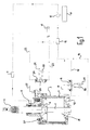
- FIGS. 1 to 3 A based on in the FIGS. 1 to 3 Embodiments shown illustrated mold opening and closing mechanism according to the invention of a glass machine not otherwise shown in the figures serves to open and close preform holder of the glass machine to remove parisons produced in the preforms from the preforms, in to hand over the finished molds and to be able to remove finished blown glass articles from the finished molds.
- FIGS. 1 to 3 shown compressed air cylinder drive 3.
- the compressed air cylinder drive 3 has a compressed air cylinder 4, in which a connected to a piston rod 5 piston 6 in up and down direction is movable; the adjusting member 2 of the rest in the FIGS. 1 to 3 not shown mold opening and closing mechanism is fixed to the piston rod 5, namely at the end of the compressed air cylinder 4 projecting end portion.
- a displacement sensor 8 is provided in the upper region of the air cylinder 4, by means of which the movement of the piston rod 5 and thus of the piston 6 within the air cylinder 4 of the compressed air cylinder drive 3 is continuously detectable.
- the displacement sensor 8 is connected to a signal evaluation unit 9 in which the displacement sensor signals can be converted into position, speed and / or acceleration data relating to the piston movement in the compressed air cylinder 4.
- the data generated and output by the signal evaluation unit 9 are the actual values for the control of the operation of the air cylinder drive 3 of the mold opening and closing mechanism.
- the aforementioned actual values are forwarded to a comparison unit 10, which is also connected to an input / output unit 11, by means of the desired values for the position, the speed and / or the acceleration of the piston movement in the compressed air cylinder 4 to the comparison unit 10 can be conducted.
- the comparison unit 10 the actual values are compared with the desired values; a deviation of the actual values from the desired values is forwarded by the comparison unit 10 to a control unit 12.
- the control unit 12 is also connected to a signal generator 13, which indicates to the control unit 12, whether the compressed air cylinder drive 3 in the feed operation, in which the piston 6 moves in the upward direction, or in the retreat mode, in which the piston 6 in the downward direction emotional. For this purpose, additionally corresponding signals which are detected by the displacement sensor 8 can be taken into account.
- the control unit 12 is connected via corresponding control lines 14, 15 to a first proportional valve 16.
- the first proportional valve 16 is in turn connected via a compressed air line 17 and provided on the compressed air cylinder 4 connecting elements 18 with the feed space 19 of the pneumatic cylinder drive 3, which in the in the FIGS. 1 to 3 shown embodiments is always disposed below the piston 6 of the pneumatic cylinder drive 3.
- the first proportional valve 16 has a blocking position "0", a loading position "2" and a relaxation position "1".
- the compressed air source 20 via the first proportional valve 16 in communication with the compressed air line 17 and thus the feed space 19 of the compressed air cylinder drive 3.
- the flow through the first proportional valve 16 is infinitely adjustable by means of the control unit 12.
- the first proportional valve 16 connects a connection between the compressed air line 17 and thus the feed space 19 of the compressed air cylinder drive 3 with the damping device 21.
- the existing in the feed space 19 air can thus flow to the damping device 21, wherein also in this state of the first Proportional valve 16, the flow can be controlled continuously by means of the control unit 12.
- control unit 12 is connected via control lines 22, 23 to a second proportional valve 24.
- the second proportional valve 24 is in turn connected via a compressed air line 25 and provided on the compressed air cylinder 4 connecting elements 26 with the return space 27 of the compressed air cylinder drive 3, which in the in the FIGS. 1 to 3 shown embodiments is always located above the piston 6 of the pneumatic cylinder drive 3.
- the second proportional valve 24 has a blocking position "0", a loading position "1" and a relaxation position "2".
- the compressed air source 28 via the second proportional valve 24 in communication with the compressed air line 25 and thus the return space 27 of the compressed air cylinder drive 3.
- the flow through the second proportional valve 24 is continuously adjustable by means of the control unit 12.
- the second proportional valve 24 connects a connection between the compressed air line 25 and thus the return space 27 of the compressed air cylinder drive 3 with the damping device 29.
- the existing in the return chamber 27 air can thus flow to the damping device 29, wherein also in this state of the second Proportional valve 24, the flow rate can be controlled continuously by means of the control unit 12.
- the control unit 12 which cooperates with the signal generator 13, inputs via the control lines 14, 15 and 22, 23, respectively Signal to the first 16 and the second proportional valve 24 forwarded.
- the first proportional valve 16 switches from the blocking position "0" to the relaxation position "1".
- the first proportional valve 16 associated damping device 21 is then connected to the feed space 19 of the pneumatic cylinder drive 3.
- the second proportional valve 24 switches from the blocking position "0" to the loading position "1”.
- the return space 27 of the compressed air cylinder drive 3 is then connected to the compressed air source 28.
- Data related to the piston movement are detected by means of the displacement sensor 8 provided in the pneumatic cylinder 4 on the piston rod 5. These data are forwarded by the distance sensor 8 to the signal evaluation unit 9.
- the actual values of the piston movement originating from the signal evaluation unit 9 are compared with reference values of the piston movement transmitted from the input / output unit 11 to the comparison unit 10.
- the result of this comparison is forwarded to the control unit 12 in the form of correction signals;
- This controls the positioning of the proportional valves 16, 24 via corresponding signals, whereby the actual values of the piston movement are adapted to the desired values of the same.
- the desired movement speed can be set.
- the control unit 12 When the pre-molds or the finished molds are to be closed, the control unit 12 outputs corresponding control signals to the first 16 and the second proportional valve 24 via the control lines 14, 15 and 22, 23, respectively.
- the second proportional valve 24 switches from the loading position "1 "in the relaxation position” 2 ".
- the return space 27 of the pneumatic cylinder drive 3 is connected to the damping device 29.
- the air from the return room 27 can escape.
- the first proportional valve 16 switches from the relaxation position "1" to the application position "2". This will be the first proportional valve 16 associated compressed air source 20 connected to the feed space 19 of the compressed air cylinder drive 3.
- the compressed air source 20 assigned to the first proportional valve 16 may have a different pressure compared to the compressed air source 28 assigned to the second proportional valve 24, which may result in a different feed rate of the same compared with the retraction speed of the piston 6.
- the feed rate of the piston 6 can be adjusted arbitrarily during the feed cycle of the piston 6 by means of the two, by the control unit 12 with respect to their flow cross-section continuously controllable or adjustable proportional valves 16, 24. As a result, the advancing movement of the piston can be designed quasi arbitrarily and continuously.
- mold opening and closing mechanism is due to the two existing, controllable by means of the control unit 12 or controllable proportional valves 16, 24 an exact control in supplying or discharging the compressed air possible, whereby in a corresponding manner the opening and closing movement of the Mold holder in the retraction movement of the piston 6 and 6 can be precisely controlled in the advancing movement of the piston.
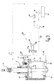
- FIG. 2 shown embodiment of the mold opening and closing mechanism according to the invention is instead of the first proportional valve 16, as in the in FIG. 1 shown embodiment, a three / two-way valve 30 is provided.
- the flow of compressed air entering through the compressed air line 17 into the feed space 19 can not be regulated.
- the advancing movement of the piston 6 can be in the in FIG. 2 embodiment shown only regulate that the flow cross-section of the second proportional valve 24, which is in its relaxation position "2", can be controlled by means of the control unit 12.
- the second proportional valve 24 switches from the blocking position "0" to the loading position "1".
- the retraction space 27 of the compressed air cylinder drive 3 is connected to the compressed air source 28 assigned to the second proportional valve 24.
- the three / two-way valve 30 switches to its relaxation position "0", whereby the feed space 19 of the pneumatic cylinder drive 3 is connected to the damping device 21 associated with the three / two-way valve 30.
- the second proportional valve 24 is switched to its relaxation position "2".
- the return space 27 of the compressed air cylinder drive 3 is connected to the damping device 29 assigned to the second proportional valve 24.
- the three / two-way valve 30 is placed in its apply position "1".
- the compressed air source 20 assigned to the three / two-way valve 30 is connected to the feed space 19 of the pneumatic cylinder drive 3.
- FIG. 3 An embodiment of the mold opening and closing mechanism according to the invention is described in which the first proportional valve 16 and the second proportional valve 24 are configured in the form of a single valve assembly 31.
- the valve assembly 31 is associated with a common compressed air source 32 realized by both of them, and a common damping device 33 realized by the valve assembly 31.
- the operation of the embodiment according to FIG. 3 is essentially the same FIG. 1 described embodiment.
- valve assembly 31 switches to the "2" position on the basis of corresponding signals from the control unit 12, a connection is established between the compressed air source 32 assigned to the valve assembly 31 and the return space 27 of the pneumatic cylinder drive 3.
- the feed space 19 of the compressed-air cylinder drive 3 is connected to the damping unit 33 assigned to the valve unit 31.
- the piston 6 of the pneumatic cylinder drive 3 in the FIGS. 1 to 3 moved in a downward direction.
Landscapes
- Engineering & Computer Science (AREA)
- Chemical & Material Sciences (AREA)
- Mechanical Engineering (AREA)
- Manufacturing & Machinery (AREA)
- Materials Engineering (AREA)
- Organic Chemistry (AREA)
- Fluid-Pressure Circuits (AREA)
Applications Claiming Priority (1)
| Application Number | Priority Date | Filing Date | Title |
|---|---|---|---|
| DE200920003558 DE202009003558U1 (de) | 2009-03-12 | 2009-03-12 | Formenöffnungs- und -schließmechanismus einer Glasmaschine |
Publications (1)
| Publication Number | Publication Date |
|---|---|
| EP2230218A1 true EP2230218A1 (fr) | 2010-09-22 |
Family
ID=42084510
Family Applications (1)
| Application Number | Title | Priority Date | Filing Date |
|---|---|---|---|
| EP10000656A Withdrawn EP2230218A1 (fr) | 2009-03-12 | 2010-01-22 | Mécanisme d'ouverture et de fermeture de moulage d'une machine de moulage de verre |
Country Status (2)
| Country | Link |
|---|---|
| EP (1) | EP2230218A1 (fr) |
| DE (1) | DE202009003558U1 (fr) |
Citations (4)
| Publication number | Priority date | Publication date | Assignee | Title |
|---|---|---|---|---|
| US4070174A (en) * | 1975-07-07 | 1978-01-24 | Emhart Industries, Inc. | Glassware forming machine of the I.S. type with in-line mold motion |
| EP0733597A2 (fr) * | 1995-03-21 | 1996-09-25 | Gps Glasproduktions-Service Gmbh | Appareil pour ouvrir et fermer des moules, en particulier des moules ébaucheurs d'une machine I.S. |
| DE69402974T2 (de) * | 1993-04-01 | 1997-10-23 | Emhart Glass Mach Invest | Steuereinrichtung für eine glasformmaschine |
| EP1127853A2 (fr) * | 2000-02-22 | 2001-08-29 | BOTTERO S.p.A. | Procédé de fabrication d' objets creux en verre et machine pour appliquer ledit procédé |
-
2009
- 2009-03-12 DE DE200920003558 patent/DE202009003558U1/de not_active Expired - Lifetime
-
2010
- 2010-01-22 EP EP10000656A patent/EP2230218A1/fr not_active Withdrawn
Patent Citations (4)
| Publication number | Priority date | Publication date | Assignee | Title |
|---|---|---|---|---|
| US4070174A (en) * | 1975-07-07 | 1978-01-24 | Emhart Industries, Inc. | Glassware forming machine of the I.S. type with in-line mold motion |
| DE69402974T2 (de) * | 1993-04-01 | 1997-10-23 | Emhart Glass Mach Invest | Steuereinrichtung für eine glasformmaschine |
| EP0733597A2 (fr) * | 1995-03-21 | 1996-09-25 | Gps Glasproduktions-Service Gmbh | Appareil pour ouvrir et fermer des moules, en particulier des moules ébaucheurs d'une machine I.S. |
| EP1127853A2 (fr) * | 2000-02-22 | 2001-08-29 | BOTTERO S.p.A. | Procédé de fabrication d' objets creux en verre et machine pour appliquer ledit procédé |
Also Published As
| Publication number | Publication date |
|---|---|
| DE202009003558U1 (de) | 2010-07-22 |
Similar Documents
| Publication | Publication Date | Title |
|---|---|---|
| EP2263855B1 (fr) | Machine de formage par soufflage entraînée de manière électrique et le procédé | |
| EP0280056B1 (fr) | Presse hydraulique de forgeage à froid | |
| EP2091715B1 (fr) | Procédé de fabrication de récipients | |
| EP3015248A1 (fr) | Procede et dispositif de transformations d'ebauches en plastique avec modification de coupe transversale d'un debit volumetrique | |
| EP1759780B1 (fr) | Dispositif de formage per étirage profond à plusieurs étages commandés indépendamment | |
| EP2915651A1 (fr) | Procédé de fabrication de corps creux en matière plastique formés par soufflage et tête d'extrusion multiple permettant de réaliser le procédé | |
| DE102012103957B4 (de) | Vorrichtung zur Herstellung von Hohlkörpern aus einer Glasschmelze | |
| DE60110291T2 (de) | Verfahren zur Herstellung von Hohlglaswaren und Maschine zur Ausführung dieses Verfahren | |
| EP2705941B1 (fr) | Procédé de fabrication de corps creux en matière plastique formés par soufflage et tête d'extrusion multiple permettant de réaliser le procédé | |
| DE10339004B4 (de) | Hydraulische Presse | |
| EP2230218A1 (fr) | Mécanisme d'ouverture et de fermeture de moulage d'une machine de moulage de verre | |
| EP2230219A1 (fr) | Mécanisme de tête de moulage d'une machine de moulage de verre | |
| EP2230220A1 (fr) | Mécanisme de poinçon-ébaucheur d'une machine de moulage de verre | |
| DE102009012930B4 (de) | Invertmechanismus einer Glasmaschine und Verfahren zur Steuerung | |
| EP2230215A1 (fr) | Mécanisme de fond ébaucheur d'une machine de moulage de verre | |
| EP3711926A1 (fr) | Dispositif de soupape de soufflage pour un dispositif de soufflage | |
| DE202009003555U1 (de) | Trichtermechanismus einer Glasmaschine | |
| EP3580035B1 (fr) | Dispositif et procédé pour transformer des préformes en matière plastique en bouteilles en matière plastique comprenant une partie fond mobile | |
| EP1002960B1 (fr) | Dispositif pour le réglage de pression de presse pour un outil ou une partie d'un outil d'une machine pour la fabrication de verre | |
| EP2230217B1 (fr) | Station d'ébauche d'une machine IS | |
| EP2397305A2 (fr) | Machine de formage par soufflage avec tige d'étirage | |
| DE102009050390A1 (de) | Arbeitsverfahren und Einrichtung zum Betreiben von Pressen | |
| DE102010022173A1 (de) | Pressenantrieb | |
| DE2334431A1 (de) | Verfahren und vorrichtung zur selbsttaetigen ueberwachung des gewichtes von gegenstaenden in einer maschine zur herstellung von glaswaren |
Legal Events
| Date | Code | Title | Description |
|---|---|---|---|
| PUAI | Public reference made under article 153(3) epc to a published international application that has entered the european phase |
Free format text: ORIGINAL CODE: 0009012 |
|
| AK | Designated contracting states |
Kind code of ref document: A1 Designated state(s): AT BE BG CH CY CZ DE DK EE ES FI FR GB GR HR HU IE IS IT LI LT LU LV MC MK MT NL NO PL PT RO SE SI SK SM TR |
|
| AX | Request for extension of the european patent |
Extension state: AL BA RS |
|
| 17P | Request for examination filed |
Effective date: 20110303 |
|
| 17Q | First examination report despatched |
Effective date: 20130913 |
|
| RAP1 | Party data changed (applicant data changed or rights of an application transferred) |
Owner name: ROLF THEMANN & PARTNER SA |
|
| GRAP | Despatch of communication of intention to grant a patent |
Free format text: ORIGINAL CODE: EPIDOSNIGR1 |
|
| INTG | Intention to grant announced |
Effective date: 20170623 |
|
| RIN1 | Information on inventor provided before grant (corrected) |
Inventor name: DIEKAEMPER, LARS Inventor name: TIMMERMANN, BERND |
|
| STAA | Information on the status of an ep patent application or granted ep patent |
Free format text: STATUS: THE APPLICATION IS DEEMED TO BE WITHDRAWN |
|
| 18D | Application deemed to be withdrawn |
Effective date: 20171104 |