EP2230372B1 - Sicherheitsschleuse - Google Patents
Sicherheitsschleuse Download PDFInfo
- Publication number
- EP2230372B1 EP2230372B1 EP20100305235 EP10305235A EP2230372B1 EP 2230372 B1 EP2230372 B1 EP 2230372B1 EP 20100305235 EP20100305235 EP 20100305235 EP 10305235 A EP10305235 A EP 10305235A EP 2230372 B1 EP2230372 B1 EP 2230372B1
- Authority
- EP
- European Patent Office
- Prior art keywords
- passage
- release
- leaf
- door
- entry
- Prior art date
- Legal status (The legal status is an assumption and is not a legal conclusion. Google has not performed a legal analysis and makes no representation as to the accuracy of the status listed.)
- Active
Links
Images

Classifications
-
- E—FIXED CONSTRUCTIONS
- E05—LOCKS; KEYS; WINDOW OR DOOR FITTINGS; SAFES
- E05G—SAFES OR STRONG-ROOMS FOR VALUABLES; BANK PROTECTION DEVICES; SAFETY TRANSACTION PARTITIONS
- E05G5/00—Bank protection devices
- E05G5/003—Entrance control
-
- E—FIXED CONSTRUCTIONS
- E05—LOCKS; KEYS; WINDOW OR DOOR FITTINGS; SAFES
- E05Y—INDEXING SCHEME ASSOCIATED WITH SUBCLASSES E05D AND E05F, RELATING TO CONSTRUCTION ELEMENTS, ELECTRIC CONTROL, POWER SUPPLY, POWER SIGNAL OR TRANSMISSION, USER INTERFACES, MOUNTING OR COUPLING, DETAILS, ACCESSORIES, AUXILIARY OPERATIONS NOT OTHERWISE PROVIDED FOR, APPLICATION THEREOF
- E05Y2800/00—Details, accessories and auxiliary operations not otherwise provided for
- E05Y2800/74—Specific positions
- E05Y2800/742—Specific positions abnormal
- E05Y2800/746—Specific positions abnormal emergency or extended
-
- E—FIXED CONSTRUCTIONS
- E05—LOCKS; KEYS; WINDOW OR DOOR FITTINGS; SAFES
- E05Y—INDEXING SCHEME ASSOCIATED WITH SUBCLASSES E05D AND E05F, RELATING TO CONSTRUCTION ELEMENTS, ELECTRIC CONTROL, POWER SUPPLY, POWER SIGNAL OR TRANSMISSION, USER INTERFACES, MOUNTING OR COUPLING, DETAILS, ACCESSORIES, AUXILIARY OPERATIONS NOT OTHERWISE PROVIDED FOR, APPLICATION THEREOF
- E05Y2900/00—Application of doors, windows, wings or fittings thereof
- E05Y2900/10—Application of doors, windows, wings or fittings thereof for buildings or parts thereof
- E05Y2900/116—Application of doors, windows, wings or fittings thereof for buildings or parts thereof for sluices
-
- E—FIXED CONSTRUCTIONS
- E05—LOCKS; KEYS; WINDOW OR DOOR FITTINGS; SAFES
- E05Y—INDEXING SCHEME ASSOCIATED WITH SUBCLASSES E05D AND E05F, RELATING TO CONSTRUCTION ELEMENTS, ELECTRIC CONTROL, POWER SUPPLY, POWER SIGNAL OR TRANSMISSION, USER INTERFACES, MOUNTING OR COUPLING, DETAILS, ACCESSORIES, AUXILIARY OPERATIONS NOT OTHERWISE PROVIDED FOR, APPLICATION THEREOF
- E05Y2900/00—Application of doors, windows, wings or fittings thereof
- E05Y2900/10—Application of doors, windows, wings or fittings thereof for buildings or parts thereof
- E05Y2900/13—Type of wing
- E05Y2900/132—Doors
Definitions
- the present invention relates to the field of access control in a protected space and relates to a security lock with unipersonal entry door.
- Security locks with a single-door entrance door are already known which form an intermediate space putting in communication an outer space and a protected space and which are provided to ensure a uniqueness of passage, that is to say to not authorize the passage from one space to another only by one person at a time.
- Such a unipersonal door security door is generally constituted by an individualization cabin, generally located in the protected space, accessible by a single person and a single-entry entrance door to the protected space. which comprises a passage flap cooperating with said cabin.
- the passage flap is pivotally mounted, between a closed position of the unipersonal entry door and an intermediate open position, to ensure uniqueness of passage by allowing entry into the individualization cabin, respectively the exit of the latter, to one person at a time.
- the intermediate opening position of the passage flap corresponds to a pivoting position of the passage flap where the latter is in contact with a part of the individualization cabin or in the immediate vicinity thereof so as to allow a passage opening.
- the closure of the unipersonal entry door by the passage flap frees entry into the personalization cabin from the protected space and, when a person is present in said cabin, the pivoting of the passage flap to in the middle open position has the effect of opening the front door unipersonal and to allow said person to go out into the outdoor space.
- U.S. Patent No. 4,947,765 discloses such a security lock comprising two walls extending at a distance from a main door passage flap and forming with this passage flap, in an intermediate opening position, a space of individualization, which can not be taken out only after closing the door to enter a protected room.
- this type of airlock does not allow to release a passage of a width sufficient to meet including a need for security during an emergency evacuation or for passing large objects.
- the document EP 1 189 178 relates to a passage device for a protected space comprising a passage flap which is pivotally held to a movable frame pivotally mounted to the side of the building so that it can be pivoted out about a vertical axis to put in clearance configuration the door. It also comprises an individualization cabin associated with the free vertical edge of the passage flap, including a first partition, which, in operation, leads from the plane of the frame, as well as a second partition spaced from this plane, in which the cabin of individualization is arranged in the protected space.
- the security chamber described in this document comprises a mobile frame which must be adapted specifically with additional pivoting and unlocking means to be movable pivotally, together with the gate flap, outwards in order to put the airlock in a situation of disengagement, which complicates the structure of the airlock and increases all its cost price.
- the mobility of the sleeping frame does not allow an adaptation of the airlock on fixed dormant frames.
- the document FR 2,855,549 relates to a device for secure access to a room comprising a first door pivoting about a first axis capable of closing at least partially the opening of the door, and a second door pivoting about a second axis, separate from said first axis and a release flap.
- the airlock described in this document requires, in addition to the presence of a release flap, the presence of two consecutive passage flaps to cross the airlock from outside to the secure local and reciprocally, namely a first passing flap to access the airlock from the outside and a second passing flap to access the secure room from the airlock.
- Such an airlock has a complex constitution resulting in a high manufacturing cost and does not allow a configuration of quick and easy release, depending on the requirements, including security or the passage of bulky goods.
- the object of the present invention is to overcome these drawbacks by proposing a unipersonal door security lock with the possibility of modulating the dimensions of the main entrance opening as a function of the passage requirements, in particular for passing large objects. dimensions or to allow an emergency evacuation of the people present in the protected premises, while being moreover of simpler design than known security locks such as those described above, with a lower cost.
- the unipersonal door security lock intended to allow access control in a protected space comprises a double-leafed single-door entry door having a single passage flap to ensure both the door and the door. entry into the airlock from outside and entry into the protected space from the airlock and vice versa. cooperating with an individualization cabin, said passage flap being pivotally mounted between a closing position of the unipersonal entrance door and an intermediate opening position in said individualization cabin to ensure uniqueness of passage and allow the entry into the individualization booth or the exit of the latter.
- Such a security lock is essentially characterized in that the double-leaf door comprises a fixed fixed frame in which are pivotally mounted a passage flap and a release flap, said release flap being locked in said fixed fixed frame in access control configuration of the single-door entry door, in that a set of unlocking means is able to release, on the one hand, the pivoting of the passage flap beyond its position intermediate opening into a disengaged opening position and, on the other hand, pivoting of the disengagement leaf into a disengagement opening position, for disengagement configuration of the unipersonal entrance door.
- said respectively passage and clearance flaps are assembled to the vertical uprights of the fixed fixed frame by means of a specific shaped round pivot connection ifiquement to allow a pivoting of said leaves on at least 180 ° so as to allow an opening of said leaves within the protected space, to allow in particular the passage of large objects, or outside said space protected, in particular in case of lack of space inside or to facilitate an emergency evacuation of the persons present in said protected space.
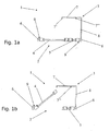
- the figures show a unipersonal door security lock, according to the present invention, intended to allow access control in a protected space 1 of the type comprising a single-door entrance door 2 comprising a passing door 4 cooperating with a cabin of 3, said passage flap 4 being pivotally mounted between a closed position of the unipersonal entrance door 2 and an intermediate open position ( figure 1b ) in said individualization cabin 3 to ensure uniqueness of passage and allow entry into the individualization booth or the exit of the latter.
- the unipersonal entrance door 2 is a double-leaf door 4, 5 comprising a fixed fixed frame 6 in which are pivotally mounted a passage flap 4 and a release flap 5, said release flap 5 being locked in said fixed fixed frame 6 in access control configuration of the unipersonal entrance door 2.
- a set of unlocking means will be able to release, on the one hand, the pivoting of the passage flap 4 beyond its intermediate open position ( figure 1b ) to a release opening position ( Figure 1c, Figure 1d ) and, on the other hand, the pivoting of the release flap 5 for an opening in a disengagement opening position, this for a setting in release configuration of the unipersonal entrance door 2 allowing, in particular, the passage of large equipment or emergency evacuation.
- double-leaf door 4, 5 is meant two wings 4, 5 pivotally mounted relative to one another in a fixed fixed frame 6, each around a vertical axis, so that their pivoting fits into each other. more particularly in two adjacent or substantially adjacent circles.
- the personalization booth 3 may comprise a movable partition 7 situated at a distance from the unipersonal entry door 2, preferably on the side of the release flap 5, which can be folded down in unipersonal entrance door release configuration 2.
- the movable partition 7 will comprise an unlocking means making it possible, on the one hand, to maintain it in a position forming a partition of the individualisation booth 3, preferably by extending parallel or substantially parallel to the fixed frame 6 ( Figures 1a and 1b ) and, on the other hand, after unlocking, to release it in pivoting, in particular in view of its folding in the configuration of the unipersonal entrance door 2 ( figures 1b , 1c and 1d ).
- the folding of the movable partition 7 corresponds to a free pivoting of said partition 7 about a vertical axis 7 "allowing it to be folded perpendicularly or substantially perpendicular to the fixed frame 6 that is outward of the protected space 1 as shown in the figures, or in a variant towards the inside of the latter.
- the movable partition 7 is advantageously pivotally mounted on a wall or a fixed partition wall 8 which preferably extends perpendicularly or substantially perpendicularly to the fixed fixed frame 6.
- the folding of the movable partition 7 will therefore be carried out in the direction of said wall wall or fixed partition 8 in a direction of pivot towards the outside of the protected space 1 (as shown in the figures) or in a variant towards the inside of the latter.
- the movable partition 7 may be able to prevent the opening of the passage flap 4 beyond the intermediate opening position and the unlocking of said movable partition 7 will then have the effect of also releasing the pivoting of the passage flap 4 to beyond the intermediate open position to bring it into a release opening position.
- the movable partition 7 is provided at its free end edge with a protruding piece 7 'forming a stop of the passage flap 4 so as to limit the pivoting thereof until at the intermediate open position.
- This intermediate opening position of the passage flap 4, which is defined when the latter comes into abutment of the projecting piece 7 ' of the movable partition 7, corresponds, on the one hand, to a sufficient opening of the unipersonal entrance door 2 so that a person can enter from the outside into the individualization cabin 3 and, on the other hand, closing the entry in the protected space 1 from the individualization cabin, as long as the flap passage 4 is maintained in said intermediate open position.
- the intermediate open position corresponds to a closing of the exit of the protected space 1 and to a sufficient opening of the unipersonal entrance door to allow the only person present in the individualization cabin and who wishes to leave from the protected area 1 to access the outdoor area.
- the passage flap 4 thus plays in a known manner the role of a passage filter allowing one person to pass at a time from an outside space to a protected space 1 and vice versa.
- said flap 4 can be held in the intermediate open position by means of a device locking device, not shown, fixed on the fixed fixed frame 6, consisting for example of a pawl system preventing a pivoting of the passage flap 4 beyond the intermediate open position, that is to say beyond beyond a pivoting position of said leaf 4 whose free end edge 4 'is located in the immediate vicinity of the movable partition 7 of the individualization booth 3 ( figure 1b ).
- a device locking device not shown, fixed on the fixed fixed frame 6, consisting for example of a pawl system preventing a pivoting of the passage flap 4 beyond the intermediate open position, that is to say beyond beyond a pivoting position of said leaf 4 whose free end edge 4 'is located in the immediate vicinity of the movable partition 7 of the individualization booth 3 ( figure 1b ).
- Unlocking the locking device may advantageously make it possible to release the pivoting of the passage flap 4 beyond the intermediate open position to bring it into a release opening position.
- the unlocking means of the locking device or the unlocking means of the movable partition 7 will constitute advantageously the unlocking means of the passage flap 4 to release it pivotally beyond the intermediate open position.
- unlocking means of the movable partition 7, the locking device, the passage flap 4 and the release flap 5 may be for example retractable locks, possibly remote controlled.
- the security lock may advantageously comprise a presence detector connected to a control electronics of a non-return device with unlocking means, not shown, adapted to block the flap 4 in the intermediate open position and closing the entrance in the protected space 1 from the individualization cabin 3, as long as the unauthorized person is present in said cabin.
- the movable partition 7 will advantageously be able to be folded, after unlocking, to allow pivoting of the passage flap 4 in a release opening position, perpendicular or substantially perpendicular to the fixed fixed frame 6, beyond the intermediate open position.
- it may be pivotally mounted, for example by means of a hinge, on a wall wall or on a fixed partition 8 which extends perpendicularly to the fixed fixed frame 6.
- the movable partition 7 and the release flap 5 will advantageously be able to be folded respectively 7 on the other 5, perpendicular or substantially perpendicular to the fixed fixed frame 6, in unipersonal 2 door entry release configuration ( figure 1c ).
- the passing door 4 and the release flap 5 will preferably be open inside ie in the protected space 1 as shown in FIG. figure 1c .
- passage flap 4 and the release flap 5 are assembled to two vertical uprights of the fixed fixed frame 6, each of which has a vertical internal face of complementary recessed contact of the outer face of rounded contact of the edge. interior of the wing 4, 5 corresponding.
- the release configuration of the entrance door can be achieved by an opening of the leaves respectively passage 4 and clearance 5 either inwardly or towards the outside, depending on the situation, while maintaining a fixed fixed frame unlike the existing airlock which comprise for this purpose a mobile frame pivotally mounted and associated with additional locking means.
- the airlock according to the present invention also has the advantage of having a single passage flap to ensure both the entry into the airlock from the outside and the entry into the protected space from the airlock and vice versa, while playing a role uniqueness by allowing the passage from one space to another by only one person, unlike the existing airlock requiring the presence of two leaves passing to cross the airlock.
- the airlock according to the present invention may advantageously comprise a central unlocking system simultaneously controlling the unlocking of the movable partition 7 with a view to its folding, the unlocking of the passage flap 4 to release its pivoting beyond the intermediate open position. to a release opening position and unlocking the release flap 5 to release its opening to a release opening position.
- the airlock according to the present invention may comprise a mechanical or electronic control non-return device to allow a single cycle or deflection per passage.
Landscapes
- Business, Economics & Management (AREA)
- Accounting & Taxation (AREA)
- Finance (AREA)
- Special Wing (AREA)
- Lock And Its Accessories (AREA)
Claims (9)
- Sicherheitsschleuse mit Ein-Personen-Tür, dazu bestimmt, die Kontrolle des Zugangs zu einem geschützten Raum (1) zu erlauben, aufweisend eine Ein-Personen-Eingangstür (2) mit zwei Flügeln (4, 5), die einen einzigen Durchgangsflügel (4) umfasst, um sowohl den Eintritt in die Schleuse von außen als auch den Eintritt in den geschützten Raum von der Schleuse aus, und umgekehrt, sicherzustellen, und die mit einer Individualisierungskabine (3) zusammenwirkt, wobei besagter Durchgangsflügel (4) zwischen einer geschlossenen Position der Ein-Personen-Eingangstür (2) und einer Zwischenöffnungs-Position in besagter Individualisierungskabine (3) verschwenkbar montiert ist, um einen Einzeldurchlass sicherzustellen und den Eintritt in die Individualisierungskabine (3) sowie das Verlassen letzterer zuzulassen,
welche Sicherheitsschleuse dadurch gekennzeichnet ist, dass besagte Tür mit zwei Flügeln (4, 5) einen festen Türrahmen (6) umfasst, in welchem besagter Durchgangsflügel (4) und ein Entlastungsflügel (5) verschwenkbar angebracht sind, wobei besagter Entlastungsflügel (5) in einer Zugangskontroll-Anordnung der Ein-Personen-Eingangstür (2) in besagtem festen Türrahmen (6) verriegelt ist, wobei eine Gesamtheit von Entriegelungsmitteln dazu ausgebildet ist, zum einen die Schwenkbewegung des Durchgangsflügels (4) über seine Position einer Zwischenöffnung hinaus bis in eine Position einer Entlastungsöffnung und zum anderen die Schwenkbewegung des Entlastungsflügels (5) in eine Position einer Entlastungsöffnung freizugeben, um die Ein-Personen-Eingangstür (2) in eineEntlastungsanordnung zu versetzen, wobei besagter Durchgangsflügel (4) oder Entlastungsflügel (5) an vertikalen Pfosten des festen Türrahmens (6) mit Hilfe einer runden Drehzapfen-Schwenkverbindung (9) montiert sind, die spezifisch angepasst ist, um ein Verschwenken besagter Flügel (4, 5) um mindestens 180° zu ermöglichen und um ein Öffnen besagter Flügel (4, 5) in das Innere des geschützten Raums (1), um insbesondere den Durchgang von Objekten großer Abmessungen zu ermöglichen, oder in den Bereich außerhalb des geschützten Raums (1) zu erlauben, insbesondere im Falle eines Platzmangels im Inneren, oder um eine Notfall-Evakuierung von Personen, die sich in demgeschützten Raum (1) befinden, zu begünstigen. - Sicherheitsschleuse nach Anspruch 1, dadurch gekennzeichnet, dass die Individualisierungskabine (3) eine mobile Trennwand (7) aufweist, die mit einem Mittel zur Entriegelung ausgestattet ist, das sich entfernt von der Ein-Personen-Eingangstür (2), vorzugsweise auf der Seite des Entlastungsflügels (5), befindet, wobei besagte mobile Trennwand (7) dazu ausgebildet ist, nach ihrer Entriegelung in die Entlastungsanordnung der Ein-Personen-Eingangstür (2) umgeklappt zu werden.
- Sicherheitsschleuse nach Anspruch 2, dadurch gekennzeichnet, dass die mobile Trennwand (7) verschwenkbar an einer Wandfläche oder an einer festen Trennwand (8), die sich senkrecht oder in etwa senkrecht zum festen Türrahmen (6) erstreckt, montiert ist.
- Sicherheitsschleuse nach einem der Ansprüche 2 bis 3, dadurch gekennzeichnet, dass die mobile Trennwand (7) dazu ausgebildet ist, das Öffnen des Durchgangsflügels (4) über die Position der Zwischenöffnung hinaus zu verhindern, und dass die Entriegelung der besagten mobilen Trennwand (7) zur Folge hat, auch das Schwenken des besagten Durchgangsflügels (4) über die Position der Zwischenöffnung hinaus freizugeben.
- Sicherheitsschleuse nach einem der Ansprüche 2 bis 3, dadurch gekennzeichnet, dass der feste Türrahmen (6) eine Sperreinrichtung mit Mitteln zur Entriegelung beinhaltet, die das Schwenken des Durchgangsflügels (4) über die Position der Zwischenöffnung hinaus unterbindet, und dass die Entriegelung besagter Sperreinrichtung es erlaubt, das Schwenken des Durchgangsflügels (4) über die Position der Zwischenöffnung hinaus freizugeben, um ihn in eine Position der Entlastungsöffnung zu bringen.
- Sicherheitsschleuse nach einem der Ansprüche 1 bis 5, dadurch gekennzeichnet, dass sie einen Präsenzmelder beeinhaltet, der an eine Steuerungselektronik einer Anti-Rückkehr-Einrichtung angeschlossen ist, welche Mittel zur Entriegelung aufweist, die dazu ausgebildet sind, den Durchgangsflügel (4) so lange in der Position der Zwischenöffnung zu sperren, wie sich eine nicht berechtigte Person in der Individualisierungskabine (3) aufhält.
- Sicherheitsschleuse nach einem der Ansprüche 2 bis 6, dadurch gekennzeichnet, dass der Entlastungsflügel (5) und die mobile Trennwand (7) dazu ausgebildet sind, senkrecht oder in etwa senkrecht zu dem festen Türrahmen (6) in der Entlastungsanordnung der Ein-Personen-Eingangstür (2) aufeinander oder in die Verlängerung voneinander umgeklappt zu werden.
- Sicherheitsschleuse nach einem der Ansprüche 1 bis 7, dadurch gekennzeichnet, dass die Durchgangs- (4) oder Entlastungsflügel (5) an vertikalen Stützen des festen Türrahmens (6) befestigt sind, die jeweils als Gegenstück zu der externen abgerundeten Kontaktfläche der Innenkante des Flügels (4, 5) eine vertikale innere vertiefte Kontaktfläche aufweisen.
- Sicherheitsschleuse nach einem der Ansprüche 1 bis 8, dadurch gekennzeichnet, dass sie ein zentralisiertes Entriegelungssyste umfasst, das gleichzeitig die Gesamtheit der Entriegelungsmittel steuert.
Applications Claiming Priority (1)
| Application Number | Priority Date | Filing Date | Title |
|---|---|---|---|
| FR0901270A FR2943376B1 (fr) | 2009-03-18 | 2009-03-18 | Sas de securite. |
Publications (2)
| Publication Number | Publication Date |
|---|---|
| EP2230372A1 EP2230372A1 (de) | 2010-09-22 |
| EP2230372B1 true EP2230372B1 (de) | 2014-01-22 |
Family
ID=41181040
Family Applications (1)
| Application Number | Title | Priority Date | Filing Date |
|---|---|---|---|
| EP20100305235 Active EP2230372B1 (de) | 2009-03-18 | 2010-03-09 | Sicherheitsschleuse |
Country Status (2)
| Country | Link |
|---|---|
| EP (1) | EP2230372B1 (de) |
| FR (1) | FR2943376B1 (de) |
Families Citing this family (2)
| Publication number | Priority date | Publication date | Assignee | Title |
|---|---|---|---|---|
| FR2972477B1 (fr) * | 2011-03-07 | 2013-08-09 | France Etat | Bloc-porte pour lieu d'enfermement, en particulier pour cellule de prison |
| ITUB20155357A1 (it) * | 2015-11-03 | 2017-05-03 | Enzo Anselmi | Dispositivo di controllo accessi a unicita' di passaggio |
Family Cites Families (4)
| Publication number | Priority date | Publication date | Assignee | Title |
|---|---|---|---|---|
| US4947765A (en) * | 1989-04-25 | 1990-08-14 | National Bulletproof, Inc. | Security apparatus and method of using same |
| EP1143386A1 (de) * | 2000-04-06 | 2001-10-10 | MS Security AG | Durchtritts-Vorrichtung |
| FR2855549B1 (fr) * | 2003-05-28 | 2007-01-05 | Serrurerie Ginon | Dispositif d'acces securise a un local |
| WO2006026790A1 (en) * | 2004-09-01 | 2006-03-09 | Brian Warren Field | Security door |
-
2009
- 2009-03-18 FR FR0901270A patent/FR2943376B1/fr not_active Expired - Fee Related
-
2010
- 2010-03-09 EP EP20100305235 patent/EP2230372B1/de active Active
Also Published As
| Publication number | Publication date |
|---|---|
| EP2230372A1 (de) | 2010-09-22 |
| FR2943376B1 (fr) | 2013-03-22 |
| FR2943376A1 (fr) | 2010-09-24 |
Similar Documents
| Publication | Publication Date | Title |
|---|---|---|
| EP2663705B1 (de) | Handgriff eines öffnungselements eines fahrzeugs mit einem griffteil | |
| CA2760396C (fr) | Dispositif de protection balistique deportee destine a couvrir completement une porte | |
| EP2230372A1 (de) | Sicherheitsschleuse | |
| EP1030028B1 (de) | Fangvorrichtung für eine vertikal bewegbare Verschlusseinrichtung | |
| FR2836946A1 (fr) | Dispositif de double verrouillage, notamment pour portillon ou analogue de barriere de protection d'une piscine | |
| FR2934300A1 (fr) | Dispositif entrebailleur pour ouvrant | |
| FR2753742A1 (fr) | Dispositif d'ancrage rapide pour volet roulant, notamment, et systeme de fermeture a tablier mobile, comme un volant roulant, ainsi equipe | |
| EP2853662B1 (de) | Schloss mit thermischer Auslöser | |
| EP1524399A1 (de) | Schutzgitter | |
| FR3075846A1 (fr) | Dispositif de commande de deverrouillage et d’ouverture, notamment en urgence, d’un ouvrant de vehicule. | |
| FR2880379A1 (fr) | Dispositif pour bloquer quel que soit sa position une fenetre, une porte, des volets et tous les ouvrants et ce quel que soit l'angle d'ouverture des ouvrants | |
| EP2660414B1 (de) | Sicherheitsschleusenvorrichtung | |
| EP1816294A1 (de) | Federgehäuse einer Fallschutzvorrichtung für Rollläden mit vertikaler Bewegungsrichtung | |
| FR2972477A1 (fr) | Bloc-porte pour lieu d'enfermement, en particulier pour cellule de prison | |
| EP1355031A1 (de) | Verriegelungsvorrichtung für ein motorisiertes Tor | |
| EP0611865A1 (de) | Verschlussvorrichtung für einen Riegel mit Mitteln zum Vermeiden fehlerhafter Bedienung | |
| EP3623564B1 (de) | Schliess- und verdunkelungsvorrichtung mit schutzgitter und einbruchsicherungssystem | |
| FR3085990A1 (fr) | Dispositif de fermeture ou d’occultation avec tablier et système anti-effraction | |
| FR3020653A1 (fr) | Dispositif de fermeture de type store, volet roulant ou similaire notamment pour fenetre de toit | |
| EP1914349A1 (de) | Vorrichtungen und Anordnung für die vorübergehende Absperrung eines Fußgängerdurchgangs, wie beispielsweise eines Flurs | |
| EP3404178A1 (de) | Verriegelungssystem am boden, das in einem torpfosten integriert ist | |
| FR2820450A1 (fr) | Gond pour grilles, grillages ouvrables et similaires | |
| FR2622243A1 (fr) | Dispositif de fermeture de securite pour portes d'entree ou coulissantes, rideaux ou volets roulants | |
| FR2739892A1 (fr) | Dispositif de securite pour porte incorporant un entrebailleur | |
| FR2773836A1 (fr) | Fermeture de porte de vehicule automobile |
Legal Events
| Date | Code | Title | Description |
|---|---|---|---|
| PUAI | Public reference made under article 153(3) epc to a published international application that has entered the european phase |
Free format text: ORIGINAL CODE: 0009012 |
|
| AK | Designated contracting states |
Kind code of ref document: A1 Designated state(s): AT BE BG CH CY CZ DE DK EE ES FI FR GB GR HR HU IE IS IT LI LT LU LV MC MK MT NL NO PL PT RO SE SI SK SM TR |
|
| AX | Request for extension of the european patent |
Extension state: AL BA ME RS |
|
| 17P | Request for examination filed |
Effective date: 20110317 |
|
| GRAP | Despatch of communication of intention to grant a patent |
Free format text: ORIGINAL CODE: EPIDOSNIGR1 |
|
| INTG | Intention to grant announced |
Effective date: 20130815 |
|
| RIC1 | Information provided on ipc code assigned before grant |
Ipc: E05G 5/00 20060101AFI20130802BHEP |
|
| GRAS | Grant fee paid |
Free format text: ORIGINAL CODE: EPIDOSNIGR3 |
|
| GRAA | (expected) grant |
Free format text: ORIGINAL CODE: 0009210 |
|
| AK | Designated contracting states |
Kind code of ref document: B1 Designated state(s): AT BE BG CH CY CZ DE DK EE ES FI FR GB GR HR HU IE IS IT LI LT LU LV MC MK MT NL NO PL PT RO SE SI SK SM TR |
|
| REG | Reference to a national code |
Ref country code: GB Ref legal event code: FG4D Free format text: NOT ENGLISH |
|
| REG | Reference to a national code |
Ref country code: CH Ref legal event code: EP |
|
| REG | Reference to a national code |
Ref country code: AT Ref legal event code: REF Ref document number: 650926 Country of ref document: AT Kind code of ref document: T Effective date: 20140215 |
|
| REG | Reference to a national code |
Ref country code: IE Ref legal event code: FG4D Free format text: LANGUAGE OF EP DOCUMENT: FRENCH |
|
| REG | Reference to a national code |
Ref country code: DE Ref legal event code: R096 Ref document number: 602010013263 Country of ref document: DE Effective date: 20140306 |
|
| REG | Reference to a national code |
Ref country code: CH Ref legal event code: NV Representative=s name: ING. MARCO ZARDI C/O M. ZARDI AND CO. S.A., CH |
|
| REG | Reference to a national code |
Ref country code: NL Ref legal event code: VDEP Effective date: 20140122 |
|
| REG | Reference to a national code |
Ref country code: AT Ref legal event code: MK05 Ref document number: 650926 Country of ref document: AT Kind code of ref document: T Effective date: 20140122 |
|
| REG | Reference to a national code |
Ref country code: LT Ref legal event code: MG4D |
|
| PG25 | Lapsed in a contracting state [announced via postgrant information from national office to epo] |
Ref country code: LT Free format text: LAPSE BECAUSE OF FAILURE TO SUBMIT A TRANSLATION OF THE DESCRIPTION OR TO PAY THE FEE WITHIN THE PRESCRIBED TIME-LIMIT Effective date: 20140122 Ref country code: NO Free format text: LAPSE BECAUSE OF FAILURE TO SUBMIT A TRANSLATION OF THE DESCRIPTION OR TO PAY THE FEE WITHIN THE PRESCRIBED TIME-LIMIT Effective date: 20140422 Ref country code: IS Free format text: LAPSE BECAUSE OF FAILURE TO SUBMIT A TRANSLATION OF THE DESCRIPTION OR TO PAY THE FEE WITHIN THE PRESCRIBED TIME-LIMIT Effective date: 20140522 |
|
| PG25 | Lapsed in a contracting state [announced via postgrant information from national office to epo] |
Ref country code: CY Free format text: LAPSE BECAUSE OF FAILURE TO SUBMIT A TRANSLATION OF THE DESCRIPTION OR TO PAY THE FEE WITHIN THE PRESCRIBED TIME-LIMIT Effective date: 20140122 Ref country code: FI Free format text: LAPSE BECAUSE OF FAILURE TO SUBMIT A TRANSLATION OF THE DESCRIPTION OR TO PAY THE FEE WITHIN THE PRESCRIBED TIME-LIMIT Effective date: 20140122 Ref country code: SE Free format text: LAPSE BECAUSE OF FAILURE TO SUBMIT A TRANSLATION OF THE DESCRIPTION OR TO PAY THE FEE WITHIN THE PRESCRIBED TIME-LIMIT Effective date: 20140122 Ref country code: PT Free format text: LAPSE BECAUSE OF FAILURE TO SUBMIT A TRANSLATION OF THE DESCRIPTION OR TO PAY THE FEE WITHIN THE PRESCRIBED TIME-LIMIT Effective date: 20140522 Ref country code: ES Free format text: LAPSE BECAUSE OF FAILURE TO SUBMIT A TRANSLATION OF THE DESCRIPTION OR TO PAY THE FEE WITHIN THE PRESCRIBED TIME-LIMIT Effective date: 20140122 Ref country code: AT Free format text: LAPSE BECAUSE OF FAILURE TO SUBMIT A TRANSLATION OF THE DESCRIPTION OR TO PAY THE FEE WITHIN THE PRESCRIBED TIME-LIMIT Effective date: 20140122 Ref country code: NL Free format text: LAPSE BECAUSE OF FAILURE TO SUBMIT A TRANSLATION OF THE DESCRIPTION OR TO PAY THE FEE WITHIN THE PRESCRIBED TIME-LIMIT Effective date: 20140122 |
|
| PG25 | Lapsed in a contracting state [announced via postgrant information from national office to epo] |
Ref country code: HR Free format text: LAPSE BECAUSE OF FAILURE TO SUBMIT A TRANSLATION OF THE DESCRIPTION OR TO PAY THE FEE WITHIN THE PRESCRIBED TIME-LIMIT Effective date: 20140122 Ref country code: LV Free format text: LAPSE BECAUSE OF FAILURE TO SUBMIT A TRANSLATION OF THE DESCRIPTION OR TO PAY THE FEE WITHIN THE PRESCRIBED TIME-LIMIT Effective date: 20140122 |
|
| REG | Reference to a national code |
Ref country code: DE Ref legal event code: R097 Ref document number: 602010013263 Country of ref document: DE |
|
| PG25 | Lapsed in a contracting state [announced via postgrant information from national office to epo] |
Ref country code: EE Free format text: LAPSE BECAUSE OF FAILURE TO SUBMIT A TRANSLATION OF THE DESCRIPTION OR TO PAY THE FEE WITHIN THE PRESCRIBED TIME-LIMIT Effective date: 20140122 Ref country code: LU Free format text: LAPSE BECAUSE OF FAILURE TO SUBMIT A TRANSLATION OF THE DESCRIPTION OR TO PAY THE FEE WITHIN THE PRESCRIBED TIME-LIMIT Effective date: 20140309 Ref country code: CZ Free format text: LAPSE BECAUSE OF FAILURE TO SUBMIT A TRANSLATION OF THE DESCRIPTION OR TO PAY THE FEE WITHIN THE PRESCRIBED TIME-LIMIT Effective date: 20140122 Ref country code: DK Free format text: LAPSE BECAUSE OF FAILURE TO SUBMIT A TRANSLATION OF THE DESCRIPTION OR TO PAY THE FEE WITHIN THE PRESCRIBED TIME-LIMIT Effective date: 20140122 Ref country code: RO Free format text: LAPSE BECAUSE OF FAILURE TO SUBMIT A TRANSLATION OF THE DESCRIPTION OR TO PAY THE FEE WITHIN THE PRESCRIBED TIME-LIMIT Effective date: 20140122 |
|
| PG25 | Lapsed in a contracting state [announced via postgrant information from national office to epo] |
Ref country code: PL Free format text: LAPSE BECAUSE OF FAILURE TO SUBMIT A TRANSLATION OF THE DESCRIPTION OR TO PAY THE FEE WITHIN THE PRESCRIBED TIME-LIMIT Effective date: 20140122 Ref country code: SK Free format text: LAPSE BECAUSE OF FAILURE TO SUBMIT A TRANSLATION OF THE DESCRIPTION OR TO PAY THE FEE WITHIN THE PRESCRIBED TIME-LIMIT Effective date: 20140122 |
|
| PLBE | No opposition filed within time limit |
Free format text: ORIGINAL CODE: 0009261 |
|
| STAA | Information on the status of an ep patent application or granted ep patent |
Free format text: STATUS: NO OPPOSITION FILED WITHIN TIME LIMIT |
|
| GBPC | Gb: european patent ceased through non-payment of renewal fee |
Effective date: 20140422 |
|
| 26N | No opposition filed |
Effective date: 20141023 |
|
| REG | Reference to a national code |
Ref country code: IE Ref legal event code: MM4A |
|
| PG25 | Lapsed in a contracting state [announced via postgrant information from national office to epo] |
Ref country code: GB Free format text: LAPSE BECAUSE OF NON-PAYMENT OF DUE FEES Effective date: 20140422 Ref country code: IE Free format text: LAPSE BECAUSE OF NON-PAYMENT OF DUE FEES Effective date: 20140309 |
|
| REG | Reference to a national code |
Ref country code: DE Ref legal event code: R097 Ref document number: 602010013263 Country of ref document: DE Effective date: 20141023 |
|
| PG25 | Lapsed in a contracting state [announced via postgrant information from national office to epo] |
Ref country code: SI Free format text: LAPSE BECAUSE OF FAILURE TO SUBMIT A TRANSLATION OF THE DESCRIPTION OR TO PAY THE FEE WITHIN THE PRESCRIBED TIME-LIMIT Effective date: 20140122 |
|
| PG25 | Lapsed in a contracting state [announced via postgrant information from national office to epo] |
Ref country code: MT Free format text: LAPSE BECAUSE OF FAILURE TO SUBMIT A TRANSLATION OF THE DESCRIPTION OR TO PAY THE FEE WITHIN THE PRESCRIBED TIME-LIMIT Effective date: 20140122 |
|
| REG | Reference to a national code |
Ref country code: FR Ref legal event code: PLFP Year of fee payment: 7 |
|
| PG25 | Lapsed in a contracting state [announced via postgrant information from national office to epo] |
Ref country code: SM Free format text: LAPSE BECAUSE OF FAILURE TO SUBMIT A TRANSLATION OF THE DESCRIPTION OR TO PAY THE FEE WITHIN THE PRESCRIBED TIME-LIMIT Effective date: 20140122 |
|
| PG25 | Lapsed in a contracting state [announced via postgrant information from national office to epo] |
Ref country code: MC Free format text: LAPSE BECAUSE OF FAILURE TO SUBMIT A TRANSLATION OF THE DESCRIPTION OR TO PAY THE FEE WITHIN THE PRESCRIBED TIME-LIMIT Effective date: 20140122 |
|
| PG25 | Lapsed in a contracting state [announced via postgrant information from national office to epo] |
Ref country code: IT Free format text: LAPSE BECAUSE OF FAILURE TO SUBMIT A TRANSLATION OF THE DESCRIPTION OR TO PAY THE FEE WITHIN THE PRESCRIBED TIME-LIMIT Effective date: 20140122 Ref country code: GR Free format text: LAPSE BECAUSE OF FAILURE TO SUBMIT A TRANSLATION OF THE DESCRIPTION OR TO PAY THE FEE WITHIN THE PRESCRIBED TIME-LIMIT Effective date: 20140423 Ref country code: BG Free format text: LAPSE BECAUSE OF FAILURE TO SUBMIT A TRANSLATION OF THE DESCRIPTION OR TO PAY THE FEE WITHIN THE PRESCRIBED TIME-LIMIT Effective date: 20140122 |
|
| PG25 | Lapsed in a contracting state [announced via postgrant information from national office to epo] |
Ref country code: TR Free format text: LAPSE BECAUSE OF FAILURE TO SUBMIT A TRANSLATION OF THE DESCRIPTION OR TO PAY THE FEE WITHIN THE PRESCRIBED TIME-LIMIT Effective date: 20140122 Ref country code: HU Free format text: LAPSE BECAUSE OF FAILURE TO SUBMIT A TRANSLATION OF THE DESCRIPTION OR TO PAY THE FEE WITHIN THE PRESCRIBED TIME-LIMIT; INVALID AB INITIO Effective date: 20100309 Ref country code: BE Free format text: LAPSE BECAUSE OF FAILURE TO SUBMIT A TRANSLATION OF THE DESCRIPTION OR TO PAY THE FEE WITHIN THE PRESCRIBED TIME-LIMIT Effective date: 20140331 |
|
| REG | Reference to a national code |
Ref country code: FR Ref legal event code: PLFP Year of fee payment: 8 |
|
| REG | Reference to a national code |
Ref country code: FR Ref legal event code: PLFP Year of fee payment: 9 |
|
| PG25 | Lapsed in a contracting state [announced via postgrant information from national office to epo] |
Ref country code: MK Free format text: LAPSE BECAUSE OF FAILURE TO SUBMIT A TRANSLATION OF THE DESCRIPTION OR TO PAY THE FEE WITHIN THE PRESCRIBED TIME-LIMIT Effective date: 20140122 |
|
| REG | Reference to a national code |
Ref country code: CH Ref legal event code: PFA Owner name: FICHET TECHNOLOGIES, FR Free format text: FORMER OWNER: GUNNEBO ELECTRONIC SECURITY (SOCIETE PAR ACTIONS SIMPLIFIEE), FR |
|
| REG | Reference to a national code |
Ref country code: DE Ref legal event code: R082 Ref document number: 602010013263 Country of ref document: DE Representative=s name: LEMCKE, BROMMER & PARTNER, PATENTANWAELTE PART, DE Ref country code: DE Ref legal event code: R081 Ref document number: 602010013263 Country of ref document: DE Owner name: FICHET TECHNOLOGIES (S.A.S.), FR Free format text: FORMER OWNER: GUNNEBO ELECTRONIC SECURITY (S.A.S.), BALDENHEIM, FR |
|
| PGFP | Annual fee paid to national office [announced via postgrant information from national office to epo] |
Ref country code: DE Payment date: 20250331 Year of fee payment: 16 |
|
| PGFP | Annual fee paid to national office [announced via postgrant information from national office to epo] |
Ref country code: CH Payment date: 20250401 Year of fee payment: 16 |
|
| REG | Reference to a national code |
Ref country code: CH Ref legal event code: U11 Free format text: ST27 STATUS EVENT CODE: U-0-0-U10-U11 (AS PROVIDED BY THE NATIONAL OFFICE) Effective date: 20260401 |
|
| PGFP | Annual fee paid to national office [announced via postgrant information from national office to epo] |
Ref country code: FR Payment date: 20260223 Year of fee payment: 17 |