EP2230410A1 - Befestigungselement - Google Patents
Befestigungselement Download PDFInfo
- Publication number
- EP2230410A1 EP2230410A1 EP10000448A EP10000448A EP2230410A1 EP 2230410 A1 EP2230410 A1 EP 2230410A1 EP 10000448 A EP10000448 A EP 10000448A EP 10000448 A EP10000448 A EP 10000448A EP 2230410 A1 EP2230410 A1 EP 2230410A1
- Authority
- EP
- European Patent Office
- Prior art keywords
- washer
- nut
- flange
- exhibitions
- wedge
- Prior art date
- Legal status (The legal status is an assumption and is not a legal conclusion. Google has not performed a legal analysis and makes no representation as to the accuracy of the status listed.)
- Granted
Links
Images



Classifications
-
- F—MECHANICAL ENGINEERING; LIGHTING; HEATING; WEAPONS; BLASTING
- F16—ENGINEERING ELEMENTS AND UNITS; GENERAL MEASURES FOR PRODUCING AND MAINTAINING EFFECTIVE FUNCTIONING OF MACHINES OR INSTALLATIONS; THERMAL INSULATION IN GENERAL
- F16B—DEVICES FOR FASTENING OR SECURING CONSTRUCTIONAL ELEMENTS OR MACHINE PARTS TOGETHER, e.g. NAILS, BOLTS, CIRCLIPS, CLAMPS, CLIPS OR WEDGES; JOINTS OR JOINTING
- F16B39/00—Locking of screws, bolts or nuts
- F16B39/22—Locking of screws, bolts or nuts in which the locking takes place during screwing down or tightening
- F16B39/24—Locking of screws, bolts or nuts in which the locking takes place during screwing down or tightening by means of washers, spring washers, or resilient plates that lock against the object
Definitions
- the invention relates to a fastening element comprising a nut, on the underside of which a flange is integrally formed, on which a washer is captively fastened.
- the invention further relates to a washer for captive rotatable attachment to a nut with integrally formed annular flange.
- Fastening elements of the aforementioned type are known from DE 94 00 671 U1 known.
- the nut body has an outer flange, which is encompassed by an integrally formed on the washer ring web. Although the washer is thus rotatable, but inseparably connected to the disc.
- the invention aims to remedy this situation.
- the invention is based on the object to provide a washer for captive, rotatable attachment to a nut, in which co-rotation is prevented when tightening the nut and beyond fully rests after tightening the nut on the contact surface. According to the invention, this object is solved by the features of claim 1.
- a washer for captive, rotatable attachment to a nut in which a co-rotation is prevented when tightening the nut and beyond fully rests after tightening the nut on the contact surface.
- the washer comes in the course of the screwing into abutment against a counter surface on the component, the flat exhibitions cause a claw in the counter surface, whereby a co-rotation of the washer is prevented.
- the exhibitions have a spring effect. The positions are continuously applied to the contact surface during the tightening of the nut and are pressed into the plane of the washer, so that a full investment of the washer is achieved.
- the two-dimensional exhibitions have a polygonal circumference.
- the rotational inhibition of the washer is improved.
- the two-dimensional exhibitions have a substantially rectangular circumference.
- the planar exhibition is arranged at an angle to the surface of the washer, so that a wedge-shaped exhibition is formed.
- a good spring effect is effected.
- a good anti-rotation is achieved in that the excellent wedge end is substantially in the direction of rotation, in which a tightening of the nut is achieved on a screw body.
- At least one exhibition is arranged, which is composed of two mutually juxtaposed wedge-shaped exhibitions, so that essentially an M-shaped surface contour is formed.
- a double exhibition allows a transverse displacement within the nut-disc composite.
- the transverse displacement results, for example, from the different thermal expansions for dissimilar materials under temperature, or bonding of materials having different outlet temperatures.
- the play of the nut within the disc in the transverse direction should be dimensioned slightly larger. Since transverse displacement forces could lead to a drive in one direction, that is, to a rotation of the disc in a simply flared disc, cause the two-sided exhibitions here a compensation, that is, the disc is also at transverse displacements stand.
- a circumferential collar is integrally formed on the washer, which is directed against the exhibition formed to surround an annular flange of a nut.
- a captive and rotatable attachment to a nut with integrally formed annular flange is possible.
- at least two integrally formed retaining claws can also be arranged circumferentially.
- the invention further relates to a fastening element, comprising a nut, on whose underside a flange is arranged, to which a washer of the aforementioned type is captively secured.
- a circumferential collar is formed on the washer, which tapers inwardly is formed, whereby an axial securing of the washer is effected on the nut.
- the nut facing the surface of the washer and the washer facing surface of the mother are coated differently.
- a specific friction value can be set between the disk and the nut.
- a friction factor with as little scattering as possible is one of the most important features of the screw connection in order to safely achieve the required preload force via the preset tightening torque of the automatic screwdriving tool.
- the fastening device chosen as an exemplary embodiment comprises a nut 2 to which a washer 1 is captively fastened.
- the nut 2 is formed in a known manner as a hexagon nut with - not Pictured - molded flange. At its top opposite the flange are on the nut 2 by extending in the axial direction slots spaced clamping tongues 21 formed.
- the clamping tongues serve to clamp the nut on a threaded rod or the like.
- the washer 1 consists essentially of an annular base plate 11, on which a circumferential collar 12 is formed, which surrounds the - not shown - flange of the nut 2.
- the captive is effected by the collar 12 is tapered upwards.
- wedge-shaped exhibitions 13 are introduced into the base plate 11 of the washer.
- the exhibitions 13 resilient tongues which are pressed when tightening the nut against a contact surface, whereby they are moved back to their original plane. The contact surface between the washer and the contact surface is thus fully utilized.
- the circumferential collar 12 is cylindrical. Only after introduction of the flange of the nut 2, the collar 12 is narrowed, whereby the captive is effected.
- the exhibitions are in the form of two oppositely arranged wedge-like exhibitions, so that a substantially M-shaped surface contour is formed.
- This dual exposure allows for transverse displacement within the nut-and-disc assembly, such as occurs with dissimilar materials under temperature.
- the game of the mother within the disc in the transverse direction is slightly larger than in the simply issued variant, such as FIG. 6 can be seen.
- the collar 12 is formed widening inwardly in the direction of the nut, whereby the desired greater game of the mother is effected.
Landscapes
- Engineering & Computer Science (AREA)
- General Engineering & Computer Science (AREA)
- Mechanical Engineering (AREA)
- Bolts, Nuts, And Washers (AREA)
- Connection Of Plates (AREA)
Abstract
Description
- Die Erfindung betrifft ein Befestigungselement, umfassend eine Mutter, an deren Unterseite ein Flansch angeformt ist, an dem eine Unterlegscheibe unverlierbar befestigt ist. Die Erfindung betrifft weiterhin eine Unterlegscheibe zur unverlierbaren drehbaren Befestigung an einer Mutter mit angeformtem Ringflansch.
- Befestigungselemente der vorgenannten Art sind aus der
DE 94 00 671 U1 bekannt. Der Mutterkörper weist einen Außenflansch auf, der von einem an der Unterlegscheibe angeformten Ringsteg umfasst wird. Die Unterlegscheibe ist damit zwar drehbar, aber unlösbar mit der Scheibe verbunden. - Nachteilig an den vorbekannten Befestigungselementen ist, dass die Unterlegscheibe sich beim Anziehen des Mutterkörpers mitdrehen kann. Darüber hinaus ist es wünschenswert, dass die Unterlegscheibe nach dem Anziehen des Mutterkörpers vollflächig auf der Anlagefläche anliegt.
- Hier will die Erfindung Abhilfe schaffen. Der Erfindung liegt die Aufgabe zu Grunde, eine Unterlegscheibe zur unverlierbaren, drehbaren Befestigung an einer Mutter zu schaffen, bei der ein Mitdrehen beim Anziehen der Mutter verhindert ist und die darüber hinaus nach dem Anziehen der Mutter vollumfänglich auf der Anlagefläche anliegt. Gemäß der Erfindung wird diese Aufgabe durch die Merkmale des Patentanspruchs 1 gelöst.
- Mit der Erfindung ist eine Unterlegscheibe zur unverlierbaren, drehbaren Befestigung an einer Mutter geschaffen, bei der ein Mitdrehen beim Anziehen der Mutter verhindert ist und die darüber hinaus nach dem Anziehen der Mutter vollumfänglich an der Anlagefläche anliegt. Die Unterlegscheibe gerät im Laufe des Schraubvorgangs in Anlage zu einer Gegenfläche am Bauteil, wobei die flächigen Ausstellungen ein Verkrallen in der Gegenfläche bewirken, wodurch ein Mitdrehen der Unterlegscheibe verhindert ist. Weiterhin weisen die Ausstellungen eine Federwirkung auf. Die Anstellungen liegen während des Anziehens der Mutter kontinuierlich an der Anlagefläche an und werden in die Ebene der Unterlegscheibe gepresst, so dass eine vollumfängliche Anlage der Unterlegscheibe erzielt ist.
- In Weiterbildung der Erfindung weisen die flächigen Ausstellungen einen mehrkantigen Umfang auf. Hierdurch ist die Drehhemmung der Unterlegscheibe verbessert. Vorzugsweise weisen die flächigen Ausstellungen einen im Wesentlichen rechteckförmigen Umfang auf.
- In Ausgestaltung der Erfindung ist die flächige Ausstellung in einem Winkel zur Oberfläche der Unterlegscheibe angeordnet, so dass eine keilförmige Ausstellung gebildet ist. Hierdurch ist eine gute Federwirkung bewirkt. Eine gute Verdrehsicherung ist dadurch erzielbar, dass das hervorragende Keilende im Wesentlichen in die Drehrichtung zeigt, in der ein Anziehen der Mutter auf einem Schraubenkörper erzielt wird.
- Vorteilhaft ist wenigstens eine Ausstellung angeordnet, welche aus zwei gegeneinander angeordneten keilförmigen Ausstellungen zusammengesetzt ist, so dass im Wesentlichen eine M-förmige Flächenkontur gebildet ist. Eine solche doppelte Ausstellung ermöglicht eine Querverschiebung innerhalb des Mutter-Scheibe-Verbundes. Die Querverschiebung ergibt sich beispielsweise durch die unterschiedlichen Wärmeausdehnungen bei ungleichen Materialien unter Temperatur, oder Verbünden von Materialien mit unterschiedlichen Ausgangstemperaturen. Zu diesem Zweck sollte auch das Spiel der Mutter innerhalb der Scheibe in Querrichtung etwas größer dimensioniert sein. Da Querverschiebungskräfte bei einer einfach ausgestellten Scheibe zu einem Antrieb in eine Richtung, das heißt zu einem Drehen der Scheibe führen könnten, bewirken die beidseitigen Ausstellungen hier einen Ausgleich, das heißt, die Scheibe bleibt auch bei Querverschiebungen stehen.
- Vorteilhaft ist an der Unterlegscheibe ein umlaufender Kragen angeformt, welcher entgegen der Ausstellung gerichtet zur Umfassung eines Ringflansches einer Mutter angeformt ist. Hierdurch ist eine unverlierbare und drehbare Befestigung an einer Mutter mit angeformtem Ringflansch ermöglicht. Alternativ können auch umlaufend wenigstens zwei angeformte Haltekrallen angeordnet sein.
- Die Erfindung betrifft weiterhin ein Befestigungselement, umfassend eine Mutter, an deren Unterseite ein Flansch angeordnet ist, an dem eine Unterlegscheibe der vorgenannten Art unverlierbar befestigt ist. Bevorzugt ist an der Unterlegscheibe ein umlaufender Kragen angeformt, der nach innen verjüngt ausgebildet ist, wodurch eine axiale Sicherung der Unterlegscheibe an der Mutter bewirkt ist.
- Vorteilhaft sind die der Mutter zugewandten Oberfläche der Unterlegscheibe und die der Unterlegscheibe zugewandte Oberfläche der Mutter unterschiedlich beschichtet. Hierdurch ist zwischen Scheibe und Mutter ein gezielter Reibwert einstellbar. Ein Reibfaktor mit möglichst geringer Streuung ist einer der wichtigsten Merkmale bei der Verschraubung, um über das voreingestellte Anziehdrehmoment des automatischen Schraubwerkzeuges sicher die erforderliche Vorspannkraft zu erreichen.
- Andere Weiterbildungen und Ausgestaltungen der Erfindung sind in den übrigen Unteransprüchen angegeben. Ein Ausführungsbeispiel der Erfindung ist in der Zeichnung dargestellt und wird nachfolgend im Einzelnen beschrieben. Es zeigen:
- Fig. 1
- Die dreidimensionale Darstellung einer Mutter mit unverlierbar angeordneter Unterlegscheibe;
- Fig. 2
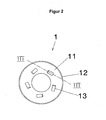
- die Unterlegscheibe aus
Fig. 1 in der Ansicht von oben; - Fig. 3
- die Unterlegscheibe aus
Fig. 2 im Schnitt III-III; - Fig. 4
- die dreidimensionale Darstellung einer Mutter mit unverlierbar befestigter Unterlegscheibe in einer weiteren Ausführungsform;
- Fig. 5
- die Unterlegscheibe aus
Fig. 4 in der Ansicht von oben und - Fig. 6
- die Unterlegscheibe aus
Fig. 5 im Schnitt VI-VI. - Die als Ausführungsbeispiel gewählte Befestigungsvorrichtung umfasst eine Mutter 2, an der eine Unterlegscheibe 1 unverlierbar befestigt ist. Die Mutter 2 ist in bekannter Art und Weise als Sechskantmutter mit - nicht dargestelltem - angeformtem Flansch ausgebildet. An ihrer dem Flansch entgegengesetzten Oberseite sind an der Mutter 2 durch in axialer Richtung verlaufende Schlitze beabstandete Klemmzungen 21 angeformt. Die Klemmzungen dienen der Klemmsicherung der Mutter an einer Gewindestange oder dergleichen.
- Die Unterlegscheibe 1 besteht im Wesentlichen aus einer ringförmigen Grundplatte 11, an der ein umlaufender Kragen 12 angeformt ist, der den - nicht dargestellten - Flansch der Mutter 2 umschließt. Die Verliersicherung ist dadurch bewirkt, dass der Kragen 12 nach oben sich verjüngend ausgebildet ist. An ihrer der Mutter 2 entgegengesetzten Unterseite sind in die Grundplatte 11 der Unterlegscheibe 2 keilförmige Ausstellungen 13 eingebracht. Wie
Figur 3 zu entnehmen, bilden die Ausstellungen 13 federnde Zungen, welche beim Anziehen der Mutter gegen eine Anlagefläche gepresst werden, wodurch diese in ihre Ursprungsebene zurückbewegt werden. Die Anlagefläche zwischen der Unterlegscheibe und der Anlagefläche wird so vollständig genutzt. InFigur 3 ist der umlaufende Kragen 12 zylindrisch ausgebildet. Erst nach Einbringen des Flansches der Mutter 2 wird der Kragen 12 verengt, wodurch die Verliersicherung bewirkt ist. - Im Ausführungsbeispiel gemäß
Figur 4 sind die Ausstellungen in Form von zwei gegenläufig angeordneten keilartigen Ausstellungen zusammengesetzt, so dass eine im Wesentlichen M-förmige Flächenkontur gebildet ist. Diese doppelte Ausstellung ermöglicht eine Querverschiebung innerhalb des Muttern-Scheiben-Verbundes, wie sie sich beispielsweise bei ungleichen Materialien unter Temperatur ergibt. Beispielhaft sei hier die Verschraubung eines Abgaskrümmers aus Stahlblech mit Anwendungstemperatur von 500° Celsius an einen wassergekühlten Zylinderkopf aus Aluminium mit ca. 120° Celsius angeführt. Zu diesem Zweck ist auch das Spiel der Mutter innerhalb der Scheibe in Querrichtung etwas größer ausgebildet, als bei der einfach ausgestellten Variante, wieFigur 6 zu entnehmen ist. Hier ist der Kragen 12 innen in Richtung der Mutter sich erweiternd ausgebildet, wodurch das erwünschte größere Spiel der Mutter bewirkt ist. - Beim Anziehen der Mutter 2 werden die zwei gegenläufig nach außen gestellten federnden Zungen der Ausstellung 13 gegen eine Anlagefläche gepresst, wodurch sie in ihre ursprüngliche Ebene (das heißt in die Ebene vor Einbringung der Ausstellung) zurückbewegt werden. Hierdurch wird wiederum die Ausnutzung der vollständigen Anlagefläche zwischen Unterlegscheibe und Anlagefläche erzielt.
Claims (10)
- Unterlegscheibe zur unverlierbaren, drehbaren Befestigung an einer Mutter mit angeformten Ringflansch, dadurch gekennzeichnet, dass an einer Seite der Unterlegscheibe (1) flächige Ausstellungen (13) ausgeformt sind.
- Unterlegscheibe nach Anspruch 1, dadurch gekennzeichnet, dass die flächigen Ausstellungen (13) einen mehrkantigen Umfang aufweisen.
- Unterlegscheibe nach Anspruch 2, dadurch gekennzeichnet, dass wenigstens eine der flächigen Ausstellungen (13) einen im Wesentlichen rechteckförmigen Umfang aufweist.
- Befestigungselement nach einem der vorgenannten Ansprüche, dadurch gekennzeichnet, dass die flächige Ausstellung (13) im Wesentlichen parallel zur Oberfläche der Unterlegscheibe (1) angeordnet ist.
- Unterlegscheibe nach einem der Ansprüche 1 bis 3, dadurch gekennzeichnet, dass die flächige Ausstellung (13) in einem Winkel zur Oberfläche der Unterlegscheibe (1) angeordnet ist, sodass eine keilförmige Ausstellung gebildet ist.
- Unterlegscheibe nach Anspruch 5, dadurch gekennzeichnet, dass die keilartige Ausstellung (13) derart an der Unterlegscheibe (1) ausgerichtet ist, dass das hervorragende Keilende im Wesentlichen in die Drehrichtung zeigt, in der ein Anziehen der Mutter (2) auf einem Schraubenkörper erzielt wird.
- Unterlegscheibe nach Anspruch 5, dadurch gekennzeichnet, dass wenigstens eine Ausstellung (13) angeordnet ist, welche aus zwei gegeneinander angeordneten keilförmigen Ausstellungen zusammengesetzt ist, sodass im Wesentlichen eine M-förmige Flächenkontur gebildet ist.
- Unterlegscheibe nach einem der vorgenannten Ansprüche, dadurch gekennzeichnet, dass an der Unterlegscheibe (1) ein umlaufender Kragen (12) angeformt ist, welcher entgegen der Ausstellungen (13) gerichtet zur Umfassung eines Ringflansches einer Mutter (2) angeformt ist.
- Befestigungselement, umfassend eine Mutter, an deren Unterseite ein Flansch angeformt ist, dadurch gekennzeichnet, dass an dem Flansch eine Unterlegscheibe (1) nach einem der vorgenannten Ansprüche unverlierbar befestigt ist.
- Befestigungselement nach Anspruch 9, dadurch gekennzeichnet, dass an der Unterlegscheibe (1) ein Umlaufender Kragen (12) angeformt ist, der den Flansch der Mutter (2) umschließend nach innen verjüngt ausgebildet ist, wodurch eine axiale Sicherung der Unterlegscheibe (1) an der Mutter (2) bewirkt ist.
Applications Claiming Priority (1)
| Application Number | Priority Date | Filing Date | Title |
|---|---|---|---|
| DE200910014162 DE102009014162A1 (de) | 2009-03-20 | 2009-03-20 | Befestigungselement |
Related Parent Applications (1)
| Application Number | Title | Priority Date | Filing Date |
|---|---|---|---|
| DE102009014162 Previously-Filed-Application | 2009-03-20 |
Publications (2)
| Publication Number | Publication Date |
|---|---|
| EP2230410A1 true EP2230410A1 (de) | 2010-09-22 |
| EP2230410B1 EP2230410B1 (de) | 2016-03-16 |
Family
ID=42236655
Family Applications (1)
| Application Number | Title | Priority Date | Filing Date |
|---|---|---|---|
| EP10000448.0A Active EP2230410B1 (de) | 2009-03-20 | 2010-01-19 | Befestigungselement |
Country Status (3)
| Country | Link |
|---|---|
| EP (1) | EP2230410B1 (de) |
| DE (1) | DE102009014162A1 (de) |
| ES (1) | ES2568763T3 (de) |
Cited By (2)
| Publication number | Priority date | Publication date | Assignee | Title |
|---|---|---|---|---|
| EP3153725A1 (de) * | 2015-10-05 | 2017-04-12 | MAN Truck & Bus AG | Verfahren und vorrichtung zur befestigung eines kunststoffbauteils an einem tragenden bauteil |
| RU2720460C1 (ru) * | 2018-10-26 | 2020-04-30 | Юнилумин Груп Ко., Лтд. | Фиксирующее приспособление для ящиков |
Families Citing this family (1)
| Publication number | Priority date | Publication date | Assignee | Title |
|---|---|---|---|---|
| DE102011118408A1 (de) * | 2011-06-18 | 2012-12-20 | Neumayer Tekfor Holding Gmbh | Befestigungselement |
Citations (5)
| Publication number | Priority date | Publication date | Assignee | Title |
|---|---|---|---|---|
| US1350545A (en) * | 1918-10-04 | 1920-08-24 | Cook Walter Herbert | Combined nut and washer |
| US2225654A (en) * | 1938-11-21 | 1940-12-24 | Illinois Tool Works | Fastener unit and method of making same |
| DE9400671U1 (de) | 1994-01-17 | 1994-03-17 | Hermann Winker GmbH & Co. KG, 78549 Spaichingen | Scheibenmutter |
| EP1091135A2 (de) * | 1999-10-08 | 2001-04-11 | TEXTRON VERBINDUNGSTECHNIK GmbH & Co. OHG | Unterlegscheibe |
| DE20317178U1 (de) * | 2003-11-04 | 2005-03-17 | Wink Hermann Metallwarenfabrik | Unterlegscheibe und Befestigungselement |
Family Cites Families (1)
| Publication number | Priority date | Publication date | Assignee | Title |
|---|---|---|---|---|
| GB420698A (en) * | 1933-07-17 | 1934-12-06 | Heyman Rosenberg | Improvements in lock washers |
-
2009
- 2009-03-20 DE DE200910014162 patent/DE102009014162A1/de not_active Withdrawn
-
2010
- 2010-01-19 EP EP10000448.0A patent/EP2230410B1/de active Active
- 2010-01-19 ES ES10000448.0T patent/ES2568763T3/es active Active
Patent Citations (5)
| Publication number | Priority date | Publication date | Assignee | Title |
|---|---|---|---|---|
| US1350545A (en) * | 1918-10-04 | 1920-08-24 | Cook Walter Herbert | Combined nut and washer |
| US2225654A (en) * | 1938-11-21 | 1940-12-24 | Illinois Tool Works | Fastener unit and method of making same |
| DE9400671U1 (de) | 1994-01-17 | 1994-03-17 | Hermann Winker GmbH & Co. KG, 78549 Spaichingen | Scheibenmutter |
| EP1091135A2 (de) * | 1999-10-08 | 2001-04-11 | TEXTRON VERBINDUNGSTECHNIK GmbH & Co. OHG | Unterlegscheibe |
| DE20317178U1 (de) * | 2003-11-04 | 2005-03-17 | Wink Hermann Metallwarenfabrik | Unterlegscheibe und Befestigungselement |
Cited By (5)
| Publication number | Priority date | Publication date | Assignee | Title |
|---|---|---|---|---|
| EP3153725A1 (de) * | 2015-10-05 | 2017-04-12 | MAN Truck & Bus AG | Verfahren und vorrichtung zur befestigung eines kunststoffbauteils an einem tragenden bauteil |
| US10207565B2 (en) | 2015-10-05 | 2019-02-19 | Man Truck & Bus Ag | Method and device for fastening a plastics component to a load-bearing component |
| RU2715957C2 (ru) * | 2015-10-05 | 2020-03-04 | Ман Трак Унд Бас Аг | Способ и устройство для закрепления пластикового конструктивного элемента на несущем конструктивном элементе |
| RU2720460C1 (ru) * | 2018-10-26 | 2020-04-30 | Юнилумин Груп Ко., Лтд. | Фиксирующее приспособление для ящиков |
| US11480205B2 (en) | 2018-10-26 | 2022-10-25 | Unilumin Group Co., Ltd. | Box latch |
Also Published As
| Publication number | Publication date |
|---|---|
| EP2230410B1 (de) | 2016-03-16 |
| DE102009014162A1 (de) | 2010-09-23 |
| ES2568763T3 (es) | 2016-05-04 |
Similar Documents
| Publication | Publication Date | Title |
|---|---|---|
| DE68902630T2 (de) | Anordnung von mutter und bolzen. | |
| DE3301060C2 (de) | ||
| DE2460961B2 (de) | Vorrichtung zum aufbringen einer vorspannkraft auf einen schraubenbolzen mit mutter | |
| DE10253888B4 (de) | Befestigungseinheit | |
| EP2230410B1 (de) | Befestigungselement | |
| DE4405974C1 (de) | Schraub-Spann-Einrichtung, insbesondere zum Verbinden von Teilen von Turmkränen | |
| DE3823000C2 (de) | Befestigungselement | |
| DE68926336T2 (de) | Bolzeneinrichtung | |
| EP1264996A1 (de) | Befestigungselement mit unverlierbar daran befestigbarer Unterlegscheibe | |
| CH626432A5 (de) | ||
| DE102011010526A1 (de) | Hinterschnittanker | |
| DE3302239A1 (de) | Verbindungselement | |
| EP3567264B1 (de) | Befestigungssystem | |
| DE2412597C2 (de) | Befestigungsvorrichtung | |
| DE102010024002B4 (de) | Scheibenbremse und Verfahren zum Austauschen eines Reibbelagträgers | |
| DE202011110394U1 (de) | Schraube | |
| DE202009003957U1 (de) | Befestigungselement | |
| DE102011100246A1 (de) | Sicherungsschraube für eine Schraubverbindung | |
| DE2401300C2 (de) | Befestigungsanordnung, bestehend aus Mutter und Gewindebolzen | |
| DE7439878U (de) | Befestigungsvorrichtung | |
| DE19905706C2 (de) | Kombimutter mit schräger Unterlegscheibe | |
| EP1028259A2 (de) | Befestigungsvorrichtung zur lösbaren Verankerung eines feuerfesten Bauteiles an einem metallischen Bauteil | |
| DE3741510A1 (de) | Selbstsicherndes verbindeelement | |
| WO2006092445A2 (de) | Bauteil mit aussengewinde zum einsetzen in ein innengewinde | |
| DE202018004929U1 (de) | Klemmring mit geringem Querschnitt |
Legal Events
| Date | Code | Title | Description |
|---|---|---|---|
| PUAI | Public reference made under article 153(3) epc to a published international application that has entered the european phase |
Free format text: ORIGINAL CODE: 0009012 |
|
| AK | Designated contracting states |
Kind code of ref document: A1 Designated state(s): AT BE BG CH CY CZ DE DK EE ES FI FR GB GR HR HU IE IS IT LI LT LU LV MC MK MT NL NO PL PT RO SE SI SK SM TR |
|
| AX | Request for extension of the european patent |
Extension state: AL BA RS |
|
| 17P | Request for examination filed |
Effective date: 20110321 |
|
| 17Q | First examination report despatched |
Effective date: 20120125 |
|
| GRAP | Despatch of communication of intention to grant a patent |
Free format text: ORIGINAL CODE: EPIDOSNIGR1 |
|
| INTG | Intention to grant announced |
Effective date: 20151016 |
|
| GRAS | Grant fee paid |
Free format text: ORIGINAL CODE: EPIDOSNIGR3 |
|
| GRAA | (expected) grant |
Free format text: ORIGINAL CODE: 0009210 |
|
| INTG | Intention to grant announced |
Effective date: 20160113 |
|
| AK | Designated contracting states |
Kind code of ref document: B1 Designated state(s): AT BE BG CH CY CZ DE DK EE ES FI FR GB GR HR HU IE IS IT LI LT LU LV MC MK MT NL NO PL PT RO SE SI SK SM TR |
|
| REG | Reference to a national code |
Ref country code: GB Ref legal event code: FG4D Free format text: NOT ENGLISH |
|
| REG | Reference to a national code |
Ref country code: CH Ref legal event code: EP |
|
| REG | Reference to a national code |
Ref country code: IE Ref legal event code: FG4D Free format text: LANGUAGE OF EP DOCUMENT: GERMAN |
|
| REG | Reference to a national code |
Ref country code: AT Ref legal event code: REF Ref document number: 781509 Country of ref document: AT Kind code of ref document: T Effective date: 20160415 |
|
| REG | Reference to a national code |
Ref country code: DE Ref legal event code: R096 Ref document number: 502010011191 Country of ref document: DE |
|
| REG | Reference to a national code |
Ref country code: ES Ref legal event code: FG2A Ref document number: 2568763 Country of ref document: ES Kind code of ref document: T3 Effective date: 20160504 |
|
| REG | Reference to a national code |
Ref country code: SE Ref legal event code: TRGR |
|
| REG | Reference to a national code |
Ref country code: NL Ref legal event code: MP Effective date: 20160316 |
|
| REG | Reference to a national code |
Ref country code: LT Ref legal event code: MG4D |
|
| PG25 | Lapsed in a contracting state [announced via postgrant information from national office to epo] |
Ref country code: GR Free format text: LAPSE BECAUSE OF FAILURE TO SUBMIT A TRANSLATION OF THE DESCRIPTION OR TO PAY THE FEE WITHIN THE PRESCRIBED TIME-LIMIT Effective date: 20160617 Ref country code: NO Free format text: LAPSE BECAUSE OF FAILURE TO SUBMIT A TRANSLATION OF THE DESCRIPTION OR TO PAY THE FEE WITHIN THE PRESCRIBED TIME-LIMIT Effective date: 20160616 Ref country code: HR Free format text: LAPSE BECAUSE OF FAILURE TO SUBMIT A TRANSLATION OF THE DESCRIPTION OR TO PAY THE FEE WITHIN THE PRESCRIBED TIME-LIMIT Effective date: 20160316 Ref country code: FI Free format text: LAPSE BECAUSE OF FAILURE TO SUBMIT A TRANSLATION OF THE DESCRIPTION OR TO PAY THE FEE WITHIN THE PRESCRIBED TIME-LIMIT Effective date: 20160316 |
|
| PG25 | Lapsed in a contracting state [announced via postgrant information from national office to epo] |
Ref country code: LV Free format text: LAPSE BECAUSE OF FAILURE TO SUBMIT A TRANSLATION OF THE DESCRIPTION OR TO PAY THE FEE WITHIN THE PRESCRIBED TIME-LIMIT Effective date: 20160316 Ref country code: LT Free format text: LAPSE BECAUSE OF FAILURE TO SUBMIT A TRANSLATION OF THE DESCRIPTION OR TO PAY THE FEE WITHIN THE PRESCRIBED TIME-LIMIT Effective date: 20160316 Ref country code: NL Free format text: LAPSE BECAUSE OF FAILURE TO SUBMIT A TRANSLATION OF THE DESCRIPTION OR TO PAY THE FEE WITHIN THE PRESCRIBED TIME-LIMIT Effective date: 20160316 |
|
| PG25 | Lapsed in a contracting state [announced via postgrant information from national office to epo] |
Ref country code: IS Free format text: LAPSE BECAUSE OF FAILURE TO SUBMIT A TRANSLATION OF THE DESCRIPTION OR TO PAY THE FEE WITHIN THE PRESCRIBED TIME-LIMIT Effective date: 20160716 Ref country code: PL Free format text: LAPSE BECAUSE OF FAILURE TO SUBMIT A TRANSLATION OF THE DESCRIPTION OR TO PAY THE FEE WITHIN THE PRESCRIBED TIME-LIMIT Effective date: 20160316 Ref country code: EE Free format text: LAPSE BECAUSE OF FAILURE TO SUBMIT A TRANSLATION OF THE DESCRIPTION OR TO PAY THE FEE WITHIN THE PRESCRIBED TIME-LIMIT Effective date: 20160316 |
|
| PG25 | Lapsed in a contracting state [announced via postgrant information from national office to epo] |
Ref country code: SM Free format text: LAPSE BECAUSE OF FAILURE TO SUBMIT A TRANSLATION OF THE DESCRIPTION OR TO PAY THE FEE WITHIN THE PRESCRIBED TIME-LIMIT Effective date: 20160316 Ref country code: CZ Free format text: LAPSE BECAUSE OF FAILURE TO SUBMIT A TRANSLATION OF THE DESCRIPTION OR TO PAY THE FEE WITHIN THE PRESCRIBED TIME-LIMIT Effective date: 20160316 Ref country code: PT Free format text: LAPSE BECAUSE OF FAILURE TO SUBMIT A TRANSLATION OF THE DESCRIPTION OR TO PAY THE FEE WITHIN THE PRESCRIBED TIME-LIMIT Effective date: 20160718 Ref country code: SK Free format text: LAPSE BECAUSE OF FAILURE TO SUBMIT A TRANSLATION OF THE DESCRIPTION OR TO PAY THE FEE WITHIN THE PRESCRIBED TIME-LIMIT Effective date: 20160316 Ref country code: RO Free format text: LAPSE BECAUSE OF FAILURE TO SUBMIT A TRANSLATION OF THE DESCRIPTION OR TO PAY THE FEE WITHIN THE PRESCRIBED TIME-LIMIT Effective date: 20160316 |
|
| REG | Reference to a national code |
Ref country code: DE Ref legal event code: R097 Ref document number: 502010011191 Country of ref document: DE |
|
| PLBE | No opposition filed within time limit |
Free format text: ORIGINAL CODE: 0009261 |
|
| STAA | Information on the status of an ep patent application or granted ep patent |
Free format text: STATUS: NO OPPOSITION FILED WITHIN TIME LIMIT |
|
| REG | Reference to a national code |
Ref country code: FR Ref legal event code: PLFP Year of fee payment: 8 |
|
| PG25 | Lapsed in a contracting state [announced via postgrant information from national office to epo] |
Ref country code: DK Free format text: LAPSE BECAUSE OF FAILURE TO SUBMIT A TRANSLATION OF THE DESCRIPTION OR TO PAY THE FEE WITHIN THE PRESCRIBED TIME-LIMIT Effective date: 20160316 |
|
| 26N | No opposition filed |
Effective date: 20161219 |
|
| PG25 | Lapsed in a contracting state [announced via postgrant information from national office to epo] |
Ref country code: BG Free format text: LAPSE BECAUSE OF FAILURE TO SUBMIT A TRANSLATION OF THE DESCRIPTION OR TO PAY THE FEE WITHIN THE PRESCRIBED TIME-LIMIT Effective date: 20160616 |
|
| PG25 | Lapsed in a contracting state [announced via postgrant information from national office to epo] |
Ref country code: SI Free format text: LAPSE BECAUSE OF FAILURE TO SUBMIT A TRANSLATION OF THE DESCRIPTION OR TO PAY THE FEE WITHIN THE PRESCRIBED TIME-LIMIT Effective date: 20160316 Ref country code: BE Free format text: LAPSE BECAUSE OF NON-PAYMENT OF DUE FEES Effective date: 20170131 |
|
| REG | Reference to a national code |
Ref country code: CH Ref legal event code: PL |
|
| GBPC | Gb: european patent ceased through non-payment of renewal fee |
Effective date: 20170119 |
|
| PG25 | Lapsed in a contracting state [announced via postgrant information from national office to epo] |
Ref country code: MC Free format text: LAPSE BECAUSE OF FAILURE TO SUBMIT A TRANSLATION OF THE DESCRIPTION OR TO PAY THE FEE WITHIN THE PRESCRIBED TIME-LIMIT Effective date: 20160316 |
|
| PG25 | Lapsed in a contracting state [announced via postgrant information from national office to epo] |
Ref country code: LI Free format text: LAPSE BECAUSE OF NON-PAYMENT OF DUE FEES Effective date: 20170131 Ref country code: CH Free format text: LAPSE BECAUSE OF NON-PAYMENT OF DUE FEES Effective date: 20170131 |
|
| REG | Reference to a national code |
Ref country code: IE Ref legal event code: MM4A |
|
| PG25 | Lapsed in a contracting state [announced via postgrant information from national office to epo] |
Ref country code: LU Free format text: LAPSE BECAUSE OF NON-PAYMENT OF DUE FEES Effective date: 20170119 Ref country code: GB Free format text: LAPSE BECAUSE OF NON-PAYMENT OF DUE FEES Effective date: 20170119 |
|
| REG | Reference to a national code |
Ref country code: FR Ref legal event code: PLFP Year of fee payment: 9 |
|
| REG | Reference to a national code |
Ref country code: BE Ref legal event code: MM Effective date: 20170131 |
|
| PG25 | Lapsed in a contracting state [announced via postgrant information from national office to epo] |
Ref country code: IE Free format text: LAPSE BECAUSE OF NON-PAYMENT OF DUE FEES Effective date: 20170119 |
|
| REG | Reference to a national code |
Ref country code: AT Ref legal event code: MM01 Ref document number: 781509 Country of ref document: AT Kind code of ref document: T Effective date: 20170119 |
|
| PG25 | Lapsed in a contracting state [announced via postgrant information from national office to epo] |
Ref country code: AT Free format text: LAPSE BECAUSE OF NON-PAYMENT OF DUE FEES Effective date: 20170119 |
|
| PG25 | Lapsed in a contracting state [announced via postgrant information from national office to epo] |
Ref country code: MT Free format text: LAPSE BECAUSE OF FAILURE TO SUBMIT A TRANSLATION OF THE DESCRIPTION OR TO PAY THE FEE WITHIN THE PRESCRIBED TIME-LIMIT Effective date: 20160316 |
|
| PG25 | Lapsed in a contracting state [announced via postgrant information from national office to epo] |
Ref country code: HU Free format text: LAPSE BECAUSE OF FAILURE TO SUBMIT A TRANSLATION OF THE DESCRIPTION OR TO PAY THE FEE WITHIN THE PRESCRIBED TIME-LIMIT; INVALID AB INITIO Effective date: 20100119 |
|
| PG25 | Lapsed in a contracting state [announced via postgrant information from national office to epo] |
Ref country code: CY Free format text: LAPSE BECAUSE OF NON-PAYMENT OF DUE FEES Effective date: 20160316 |
|
| PG25 | Lapsed in a contracting state [announced via postgrant information from national office to epo] |
Ref country code: MK Free format text: LAPSE BECAUSE OF FAILURE TO SUBMIT A TRANSLATION OF THE DESCRIPTION OR TO PAY THE FEE WITHIN THE PRESCRIBED TIME-LIMIT Effective date: 20160316 |
|
| PG25 | Lapsed in a contracting state [announced via postgrant information from national office to epo] |
Ref country code: TR Free format text: LAPSE BECAUSE OF FAILURE TO SUBMIT A TRANSLATION OF THE DESCRIPTION OR TO PAY THE FEE WITHIN THE PRESCRIBED TIME-LIMIT Effective date: 20160316 |
|
| PGFP | Annual fee paid to national office [announced via postgrant information from national office to epo] |
Ref country code: SE Payment date: 20260121 Year of fee payment: 17 |
|
| PGFP | Annual fee paid to national office [announced via postgrant information from national office to epo] |
Ref country code: ES Payment date: 20260217 Year of fee payment: 17 |
|
| PGFP | Annual fee paid to national office [announced via postgrant information from national office to epo] |
Ref country code: DE Payment date: 20260116 Year of fee payment: 17 |
|
| PGFP | Annual fee paid to national office [announced via postgrant information from national office to epo] |
Ref country code: IT Payment date: 20260130 Year of fee payment: 17 |
|
| PGFP | Annual fee paid to national office [announced via postgrant information from national office to epo] |
Ref country code: FR Payment date: 20260121 Year of fee payment: 17 |