EP2230413A2 - Crochet de mousqueton - Google Patents
Crochet de mousqueton Download PDFInfo
- Publication number
- EP2230413A2 EP2230413A2 EP10001721A EP10001721A EP2230413A2 EP 2230413 A2 EP2230413 A2 EP 2230413A2 EP 10001721 A EP10001721 A EP 10001721A EP 10001721 A EP10001721 A EP 10001721A EP 2230413 A2 EP2230413 A2 EP 2230413A2
- Authority
- EP
- European Patent Office
- Prior art keywords
- hook
- closure part
- free
- snap
- hook body
- Prior art date
- Legal status (The legal status is an assumption and is not a legal conclusion. Google has not performed a legal analysis and makes no representation as to the accuracy of the status listed.)
- Withdrawn
Links
- 229910000831 Steel Inorganic materials 0.000 claims abstract description 23
- 239000010959 steel Substances 0.000 claims abstract description 23
- 238000003780 insertion Methods 0.000 claims abstract description 9
- 230000037431 insertion Effects 0.000 claims abstract description 9
- 238000005538 encapsulation Methods 0.000 claims description 16
- 229910052751 metal Inorganic materials 0.000 claims description 11
- 239000002184 metal Substances 0.000 claims description 11
- 238000005452 bending Methods 0.000 claims description 7
- 238000007765 extrusion coating Methods 0.000 claims description 4
- 238000000465 moulding Methods 0.000 abstract 2
- 238000004519 manufacturing process Methods 0.000 description 4
- 239000000463 material Substances 0.000 description 2
- 229910052782 aluminium Inorganic materials 0.000 description 1
- XAGFODPZIPBFFR-UHFFFAOYSA-N aluminium Chemical compound [Al] XAGFODPZIPBFFR-UHFFFAOYSA-N 0.000 description 1
- 230000015572 biosynthetic process Effects 0.000 description 1
- 238000010276 construction Methods 0.000 description 1
- 230000001419 dependent effect Effects 0.000 description 1
- 238000011161 development Methods 0.000 description 1
- 230000018109 developmental process Effects 0.000 description 1
- 238000001125 extrusion Methods 0.000 description 1
- 238000005498 polishing Methods 0.000 description 1
- 230000036316 preload Effects 0.000 description 1
- 239000011435 rock Substances 0.000 description 1
- 230000035939 shock Effects 0.000 description 1
Images

Classifications
-
- F—MECHANICAL ENGINEERING; LIGHTING; HEATING; WEAPONS; BLASTING
- F16—ENGINEERING ELEMENTS AND UNITS; GENERAL MEASURES FOR PRODUCING AND MAINTAINING EFFECTIVE FUNCTIONING OF MACHINES OR INSTALLATIONS; THERMAL INSULATION IN GENERAL
- F16G—BELTS, CABLES, OR ROPES, PREDOMINANTLY USED FOR DRIVING PURPOSES; CHAINS; FITTINGS PREDOMINANTLY USED THEREFOR
- F16G15/00—Chain couplings, Shackles; Chain joints; Chain links; Chain bushes
- F16G15/04—Quickly-detachable chain couplings; Shackles chain links with rapid junction means are classified according to the corresponding kind of chain
-
- F—MECHANICAL ENGINEERING; LIGHTING; HEATING; WEAPONS; BLASTING
- F16—ENGINEERING ELEMENTS AND UNITS; GENERAL MEASURES FOR PRODUCING AND MAINTAINING EFFECTIVE FUNCTIONING OF MACHINES OR INSTALLATIONS; THERMAL INSULATION IN GENERAL
- F16B—DEVICES FOR FASTENING OR SECURING CONSTRUCTIONAL ELEMENTS OR MACHINE PARTS TOGETHER, e.g. NAILS, BOLTS, CIRCLIPS, CLAMPS, CLIPS OR WEDGES; JOINTS OR JOINTING
- F16B45/00—Hooks; Eyes
- F16B45/02—Hooks with pivoting or elastically bending closing member
- F16B45/023—Hooks with pivoting or elastically bending closing member the closing member pivoting about an axis perpendicular to the plane of the hook
-
- F—MECHANICAL ENGINEERING; LIGHTING; HEATING; WEAPONS; BLASTING
- F16—ENGINEERING ELEMENTS AND UNITS; GENERAL MEASURES FOR PRODUCING AND MAINTAINING EFFECTIVE FUNCTIONING OF MACHINES OR INSTALLATIONS; THERMAL INSULATION IN GENERAL
- F16B—DEVICES FOR FASTENING OR SECURING CONSTRUCTIONAL ELEMENTS OR MACHINE PARTS TOGETHER, e.g. NAILS, BOLTS, CIRCLIPS, CLAMPS, CLIPS OR WEDGES; JOINTS OR JOINTING
- F16B45/00—Hooks; Eyes
- F16B45/02—Hooks with pivoting or elastically bending closing member
- F16B45/027—Hooks with pivoting or elastically bending closing member and having position-locking means for the closing member
- F16B45/028—Hooks with pivoting or elastically bending closing member and having position-locking means for the closing member the position-locking means being pivotally connected
Definitions
- the invention relates to a snap hook according to the preamble of the protection claim. 1
- Such a snap hook is known from practice.
- the closure part is made entirely of sheet steel.
- At its pointing to the free hook end of the hook body tip of the closure part has a bore into which a hook provided at the free hook end engages in the closed position of the closure part.
- a release position in which the closure part is moved away from the hook arranged at the free hook end and, for example, a rope can be inserted through the insertion of the snap hook in the latter, the hook is free at the hook end of the hook body from.
- the disadvantage here is that the rope when hooking or unhooking caught on the hook or can even be damaged at this.
- hook body and closure part are forged in a form-fitting manner.
- this requires a massive construction of hook body and closure part, for example, steel or aluminum.
- the invention has for its object to provide a snap hook of the type mentioned, which is easy to manufacture and safe to handle.
- the closure part is at least partially encapsulated in plastic and the encapsulation is generally designed such that elements of the positive connection are arranged protected by the encapsulation.
- the snap hook can be inexpensively manufactured on the one hand, on the other hand, the essential elements of the snap hook, namely hook body and closure part, by the plastic encapsulation very much against hard shock, such as rocks, and against the risk of formation of thus hairline cracks are protected. It is thus possible to manufacture the essential elements of the snap hook from simple sheet steel, which is not subject to any further treatment, such as a deburring or polishing of the surface. At the same time, the overmoulding of the closure part also improves the grip.
- a rope By at least partially encapsulating the closure part, for example, a rope is not exposed to the risk of suffering damage from frequent contact with the closure part. Due to the protected arrangement of elements of the positive connection of the snap hook according to the invention is very safe to handle, since a rope or other objects can not come into contact with an optionally provided on the free hook end hooks. As a result, the risk of damage to the rope is largely excluded.
- the hook body and closure part are punched out of sheet steel, so that essential elements of the snap hook can be produced in a simple manner and therefore cost-effectively.
- the free hook end of the hook body has a hook tip arranged within the contour of the extrusion coating.
- the tip of the hook is thus housed protected within the encapsulation.
- contact between the hook tip with a rope or with body parts of the user is almost impossible.
- the snap hook according to the invention is extremely safe to handle.
- the closure part is a U-shaped bent sheet metal part, wherein the sheet metal part preferably has two parallel legs, which are integrally connected to each other via a U-shaped bent portion.
- a closure part can be easily and inexpensively manufactured, requires little material and has good strength. Since the opening of the U-shaped bent sheet metal part may face the free hook end of the hook body, such a trained closure part can easily hook on the free hook end, so that the resulting positive connection can be advantageously claimed to train.
- Such trained closure part requires in contrast to the known from the aforementioned prior art snap hook significantly less material.
- the U-shaped bent portion of the sheet metal part is arranged facing the free hook end of the hook body, further, the U-shaped bending section is free on the extrusion of the closure part and is in the closed position of the closure part detachable with the free hook end of the Hook body locked.
- the free projection of the U-shaped bent portion on the extrusion coating of the closure part allows in the closed position of the closure part a simple engagement of the bending portion with the free hook end of the hook body. Since the closure member is pivoted in its release position away from the free end of the hook, a held in the snap hook cable can hardly come into contact with the U-shaped bending portion.
- the snap hook further comprises an L-shaped fuse, which is pivotally mounted on the hook body, wherein the fuse is preferably has a locking latch, which only allows a transfer of the closure part from the closed position into a release position when the fuse is transferred together with its locking bolt from a locking position into an unlocked position.
- the safe handling of the snap hook according to the invention is further improved. Unintentional opening of the snap hook is effectively prevented. A transfer of the closure part in the release position is easily made possible when the fuse is acted upon in its unlocked position.
- the fuse has a locking bar at least partially embracing actuating lever. By simply pressing the operating lever, the fuse can be transferred to its unlocked position and the closure part in its release position.
- the fuse is made of plastic with at least partially encapsulated steel sheet, wherein preferably the locking bolt made of sheet steel and the actuating lever are made of plastic.
- essential elements of the snap hook according to the invention such as hook body, closure part and fuse can be made of molded steel sheet. Such a snap hook is thus, as previously indicated, easy to manufacture and very safe to handle.
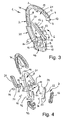
- Fig. 1 is a schematic front view of a snap hook 1 is shown.
- the snap hook 1 has a hook body 2, which has a head part 3 with a free hook end 4, a base part 5 and an insertion opening 6 formed between the base part 5 and the free hook end 4. The latter is more accurate in the 3 and 4 shown.
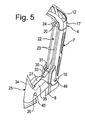
- the hook body has a closure part 7, which optionally overlaps the insertion opening 6, this position is in the Fig. 1, 2 and 5 shown, and is pivotally mounted on the base part 5.
- the one end of the closure part 7 receives the pivot axis 10; the opposite other end, hereinafter called the free end 11 of the closure part 7, is in the in the Fig. 1, 2 and 5 shown closed position of the closure part 7 with the free hook end of the hook body 2 positively connected.
- Hook body 2 and closure part 7 are made of sheet steel 8.
- the hook body 2 is at least partially encapsulated in plastic, so that the hook body is peripherally largely surrounded by an encapsulation 12.
- the closure part 7 is at least partially encapsulated in plastic.
- the openings 13 of the encapsulation 12 are also provided in the region of the closure part 7.
- the encapsulation 12 is designed such that elements of the positive connection 14 are arranged protected by the encapsulation 12.
- Hook body 2 and closure part 7 are punched out of the steel sheet 8 according to an embodiment of the invention.
- the inner edge 15 of the hook body 2 forming the steel sheet 8 and the inner edge 16 of the closure member 7 forming steel sheet are exposed and are therefore not surrounded by the encapsulation 12.
- the free hook end 4 of the hook body 2 has a hook tip 20 arranged within the contour 17 of the extrusion coating 12. This is directed inward, ie toward the inner recess 21 of the snap hook 1.
- the closure part 7 is a U-shaped bent sheet metal part 22.
- This sheet metal part has two parallel legs 23, which are integrally connected to each other via a U-shaped bent portion 24. These details are more accurate in the Fig. 4 and 5 shown.
- the U-shaped bent portion 24 of the sheet metal part 22 forms the free end 11 of the closure part 7 and is arranged to the free hook end 4 of the hook body 2 indicative.
- the bending section 24 projects freely over the encapsulation 12 of the closure part 7. In the closed position of the closure part of the bending portion 24 is releasably locked to the free hook end 4 of the hook body 2, as shown in the Fig. 1, 2 and 5 is indicated.
- the snap hook 1 further has an L-shaped fuse 25 which is pivotally mounted about a pivot axis 26 on the hook body 2.
- the fuse 25 has a locking bolt 27. This is more accurate in the Fig. 4 and 5 and allows a transfer of the closure part 7 from the in the Fig. 1, 2 and 5 illustrated closed position in one in Fig. 3 shown release position only when the fuse 25 together with its locking bolt 27 from a in Fig. 5 shown locking position is transferred to an unlocked position.
- the locking bolt 27 has on its side facing the closure part 7 side face a nose 30 which abuts in the locking position of the locking bolt 27 on a bolt 31 of the closure part 7.
- a nose 30 which abuts in the locking position of the locking bolt 27 on a bolt 31 of the closure part 7.
- At the nose 30 is connected to the opposite other side surface 32 of the locking bar 27 toward a V- or L-shaped configured ramp surface 33 at.
- the bolt 31 of the closure member 7 slide along when the fuse 25 from its in Fig. 1 shown locking position in their in the Fig. 2 and 3 shown unlocked position is transferred.
- the fuse 25 in the direction of arrow A in Fig. 1 pivoted clockwise about its pivot axis 26 until the fuse in the Fig. 2 shown unlocked position assumes.
- the locking bolt 27 in the direction of arrow B that is downwardly moved, whereby the nose 30 of the locking bar 27 out of engagement with the bolt 31 of the closure part 7 passes.
- the closure part 7 in Fig. 2 in the direction of the arrow C inward ie to the inner recess 21 of the snap hook 1 back, move, so that the snap hooks ultimately in Fig. 3 position shown assumes.
- the fuse is thus in its unlocked position and the closure part in its release position.
- the fuse 25 further has a locking bolt 27 at least partially embracing actuating lever 34.
- the locking bolt 27 is between legs 35 of the actuating lever 34 by means of a Einsteck concentratedes 36 (see Fig. 4 ) held firmly.
- the Einsteck Glacial 36 penetrates a recess 37 in the legs 35 and a recess 40 which is formed in the locking bolt 27.
- the fuse 25 is made of plastic with at least partially encapsulated steel sheet, wherein preferably the locking bolt 27 made of sheet steel and the operating lever 34 are made of plastic.
- the overmold 12 of the hook body 2 has an upper portion 41 and a lower portion 42 fixedly connected to the steel sheet 8 of the hook body.
- plug pins 43 may be formed, which are inserted into holes 44 of the steel sheet 8.
- the sections 41, 42 of the encapsulation 12 are held firmly on the steel sheet 8 of the hook body 2.
- the encapsulation 12 of the closure part 7 is connected to its sheet-metal part 22.
- Fuse 25 and closure member 7 are pivotally mounted by means of bolts 45, 46, which in Fig. 4 are shown. It is clear that the bolts 45, 46 are inserted into bores 50, 51, which are formed in the hook body 2, more precisely in the steel sheet 8 thereof.
- Strip-shaped springs 52, 53 are provided, with the aid of the fuse 25 in their in Fig. 1 shown locking position and the closure member 7 in its release position (see Fig. 3 ) are preloaded.
Landscapes
- Engineering & Computer Science (AREA)
- General Engineering & Computer Science (AREA)
- Mechanical Engineering (AREA)
- Hooks, Suction Cups, And Attachment By Adhesive Means (AREA)
- Supports Or Holders For Household Use (AREA)
Applications Claiming Priority (1)
| Application Number | Priority Date | Filing Date | Title |
|---|---|---|---|
| DE202009003905U DE202009003905U1 (de) | 2009-03-19 | 2009-03-19 | Karabinerhaken |
Publications (2)
| Publication Number | Publication Date |
|---|---|
| EP2230413A2 true EP2230413A2 (fr) | 2010-09-22 |
| EP2230413A3 EP2230413A3 (fr) | 2012-06-27 |
Family
ID=40822515
Family Applications (1)
| Application Number | Title | Priority Date | Filing Date |
|---|---|---|---|
| EP10001721A Withdrawn EP2230413A3 (fr) | 2009-03-19 | 2010-02-19 | Crochet de mousqueton |
Country Status (2)
| Country | Link |
|---|---|
| EP (1) | EP2230413A3 (fr) |
| DE (1) | DE202009003905U1 (fr) |
Families Citing this family (4)
| Publication number | Priority date | Publication date | Assignee | Title |
|---|---|---|---|---|
| FR3016008B1 (fr) * | 2013-12-27 | 2016-05-06 | Ack Forankra | Crochet pour filet de fret pour le transport aerien. |
| DE202014104023U1 (de) * | 2014-08-28 | 2014-09-09 | Thiele Gmbh & Co. Kg | Hybridhaken |
| TWI804818B (zh) * | 2021-02-22 | 2023-06-11 | 貝加工業股份有限公司 | 抗扭矩性安全鈎 |
| GB2633002A (en) * | 2023-08-11 | 2025-03-05 | Flintstone Tech Ltd | Chain connector |
Family Cites Families (6)
| Publication number | Priority date | Publication date | Assignee | Title |
|---|---|---|---|---|
| DE8204508U1 (de) * | 1982-09-16 | Niggeloh, Fritz, Dipl.-Kfm., 5608 Radevormwald | Aufhängevorrichtung, insbesondere für Tragegurte von Cameras und/oder Fernrohren | |
| DE2532251C3 (de) * | 1975-07-18 | 1979-06-07 | Salewa Sportgeraetefabrik Gmbh, 8000 Muenchen | Bergsteiger-Karabinerhaken |
| GB2356011B (en) * | 1999-11-02 | 2001-09-12 | Paul Edward Dean | Mooring catcher |
| GB0019136D0 (en) * | 2000-08-04 | 2000-09-27 | Dmm Eng Ltd | Karabiners |
| US6688259B2 (en) * | 2001-05-31 | 2004-02-10 | Wendy Axel | Handle with grip for comfortably holding articles by hand |
| US7922220B2 (en) * | 2007-02-07 | 2011-04-12 | Coulombe Don F | Safety hook |
-
2009
- 2009-03-19 DE DE202009003905U patent/DE202009003905U1/de not_active Expired - Lifetime
-
2010
- 2010-02-19 EP EP10001721A patent/EP2230413A3/fr not_active Withdrawn
Non-Patent Citations (1)
| Title |
|---|
| None |
Also Published As
| Publication number | Publication date |
|---|---|
| EP2230413A3 (fr) | 2012-06-27 |
| DE202009003905U1 (de) | 2009-07-02 |
Similar Documents
| Publication | Publication Date | Title |
|---|---|---|
| EP2127969B1 (fr) | Raclette d'essuie-glace | |
| EP3064419B1 (fr) | Antivol de cadre | |
| DE202011000341U1 (de) | Schloss für eine Klappe oder Tür | |
| DE102014115257A1 (de) | Befestigungselement für ein Belagelement beispielsweise einer Terrasse | |
| EP2230413A2 (fr) | Crochet de mousqueton | |
| WO2015124400A1 (fr) | Dispositif d'actionnement pour frein de stationnement | |
| EP2397627A2 (fr) | Dispositif de couplage et de découplage d'une poignée extérieure de porte | |
| EP3033961B1 (fr) | Systeme de boucle de ceinture | |
| DE202009013243U1 (de) | Betätigungsvorrichtung für eine Feststellbremse | |
| DE202013006032U1 (de) | Spielfigur für insbesondere ein Tischfußballgerät | |
| DE202009004463U1 (de) | Verschlusssystem mit einem auf der Verschlussstange beweglich angeordneten Federriegel | |
| DE102010035044A1 (de) | Runge für Nutzfahrzeugaufbauten | |
| DE102007013644A1 (de) | Zugentlastung eines Kabels für ein elektromotorisch betriebenes, handgeführtes Arbeitsgerät | |
| EP1907726B1 (fr) | Griffe, en particulier griffe de raccourcissement | |
| DE69012716T2 (de) | Schnappverschluss. | |
| DE102007042137B4 (de) | Betätigungsvorrichtung für eine Feststellbremse | |
| DE202013103367U1 (de) | Vorrichtung zum Verriegeln von Türen o. dgl. an Nutzfahrzeugaufbauten | |
| AT511336B1 (de) | Karabinerhaken | |
| EP1497519B1 (fr) | Verrou de basculement | |
| DE202009004833U1 (de) | Rastelement | |
| DE102004020040B4 (de) | Haken zum Anschlagen einer Anschlagkette an einem Container od. dgl. | |
| DE102017002812A1 (de) | Hebevorrichtung | |
| DE202008015715U1 (de) | Vorrichtung zur Befestigung eines Gepäckstückes | |
| DE102014112576A1 (de) | Bordwandverschluss | |
| DE102014102874A1 (de) | Halsband für Tiere, insbesondere Hunde, mit einem Klickverschluss |
Legal Events
| Date | Code | Title | Description |
|---|---|---|---|
| PUAI | Public reference made under article 153(3) epc to a published international application that has entered the european phase |
Free format text: ORIGINAL CODE: 0009012 |
|
| AK | Designated contracting states |
Kind code of ref document: A2 Designated state(s): AT BE BG CH CY CZ DE DK EE ES FI FR GB GR HR HU IE IS IT LI LT LU LV MC MK MT NL NO PL PT RO SE SI SK SM TR |
|
| AX | Request for extension of the european patent |
Extension state: AL BA RS |
|
| PUAL | Search report despatched |
Free format text: ORIGINAL CODE: 0009013 |
|
| AK | Designated contracting states |
Kind code of ref document: A3 Designated state(s): AT BE BG CH CY CZ DE DK EE ES FI FR GB GR HR HU IE IS IT LI LT LU LV MC MK MT NL NO PL PT RO SE SI SK SM TR |
|
| AX | Request for extension of the european patent |
Extension state: AL BA RS |
|
| RIC1 | Information provided on ipc code assigned before grant |
Ipc: F16B 45/02 20060101AFI20120524BHEP |
|
| 17P | Request for examination filed |
Effective date: 20121113 |
|
| 17Q | First examination report despatched |
Effective date: 20130426 |
|
| STAA | Information on the status of an ep patent application or granted ep patent |
Free format text: STATUS: THE APPLICATION IS DEEMED TO BE WITHDRAWN |
|
| 18D | Application deemed to be withdrawn |
Effective date: 20140902 |