EP2230447A2 - Lichtröhrenstruktur und Leuchte mit Lichtröhrenstruktur - Google Patents
Lichtröhrenstruktur und Leuchte mit Lichtröhrenstruktur Download PDFInfo
- Publication number
- EP2230447A2 EP2230447A2 EP10157104A EP10157104A EP2230447A2 EP 2230447 A2 EP2230447 A2 EP 2230447A2 EP 10157104 A EP10157104 A EP 10157104A EP 10157104 A EP10157104 A EP 10157104A EP 2230447 A2 EP2230447 A2 EP 2230447A2
- Authority
- EP
- European Patent Office
- Prior art keywords
- light
- light pipe
- visible
- pipe structure
- disposed
- Prior art date
- Legal status (The legal status is an assumption and is not a legal conclusion. Google has not performed a legal analysis and makes no representation as to the accuracy of the status listed.)
- Withdrawn
Links
Images



Classifications
-
- F—MECHANICAL ENGINEERING; LIGHTING; HEATING; WEAPONS; BLASTING
- F21—LIGHTING
- F21S—NON-PORTABLE LIGHTING DEVICES; SYSTEMS THEREOF; VEHICLE LIGHTING DEVICES SPECIALLY ADAPTED FOR VEHICLE EXTERIORS
- F21S6/00—Lighting devices intended to be free-standing
- F21S6/005—Lighting devices intended to be free-standing with a lamp housing maintained at a distance from the floor or ground via a support, e.g. standing lamp for ambient lighting
- F21S6/008—Lighting devices intended to be free-standing with a lamp housing maintained at a distance from the floor or ground via a support, e.g. standing lamp for ambient lighting with a combination of direct and indirect lighting
-
- F—MECHANICAL ENGINEERING; LIGHTING; HEATING; WEAPONS; BLASTING
- F21—LIGHTING
- F21V—FUNCTIONAL FEATURES OR DETAILS OF LIGHTING DEVICES OR SYSTEMS THEREOF; STRUCTURAL COMBINATIONS OF LIGHTING DEVICES WITH OTHER ARTICLES, NOT OTHERWISE PROVIDED FOR
- F21V11/00—Screens not covered by groups F21V1/00, F21V3/00, F21V7/00 or F21V9/00
- F21V11/02—Screens not covered by groups F21V1/00, F21V3/00, F21V7/00 or F21V9/00 using parallel laminae or strips, e.g. of Venetian-blind type
-
- F—MECHANICAL ENGINEERING; LIGHTING; HEATING; WEAPONS; BLASTING
- F21—LIGHTING
- F21W—INDEXING SCHEME ASSOCIATED WITH SUBCLASSES F21K, F21L, F21S and F21V, RELATING TO USES OR APPLICATIONS OF LIGHTING DEVICES OR SYSTEMS
- F21W2131/00—Use or application of lighting devices or systems not provided for in codes F21W2102/00-F21W2121/00
- F21W2131/40—Lighting for industrial, commercial, recreational or military use
- F21W2131/402—Lighting for industrial, commercial, recreational or military use for working places
-
- F—MECHANICAL ENGINEERING; LIGHTING; HEATING; WEAPONS; BLASTING
- F21—LIGHTING
- F21Y—INDEXING SCHEME ASSOCIATED WITH SUBCLASSES F21K, F21L, F21S and F21V, RELATING TO THE FORM OR THE KIND OF THE LIGHT SOURCES OR OF THE COLOUR OF THE LIGHT EMITTED
- F21Y2103/00—Elongate light sources, e.g. fluorescent tubes
Definitions
- the disclosure relates generally to luminaire, and more particularly to a luminaire with a light pipe structure.
- Light pipe structures are currently known to be disposed within luminaires in a manner that creates a luminous region at a relative side thereof.
- visible ends of these structures i.e. the areas of the structures from which light exits
- Secondary manufacturing processes designed to remedy this concentration are available, but can be costly and inefficient.
- a light pipe structure configured to reduce undesirable intensity of light without requiring secondary manufacturing processes would be desirable.
- a light pipe structure configured for transmittal of light rays, the light pipe structure including a light entry end associated with a visible end via a light pipe body, the light entry end being configured for entrance of the light rays, and a depression disposed in a visible surface of the visible end, the depression being disposed substantially along a major axis of the visible surface.
- a light pipe structure configured for transmittal of light rays
- the light pipe structure including a light entry end associated with a visible end via a light pipe body, the light entry end being configured for entrance of the light rays, a visible extension extending from the light pipe body at the visible end, and at least one angled surface disposed at a junction between the light pipe body and the visible end, the at least one angled surface being angled and disposed relative to the light pipe body to reflect at least a portion of the light rays transmitted by the light pipe structure off of a major axis of the light pipe body and into or in a direction of the visible extension.
- a luminaire configured for pipe lighting, the luminaire including a luminaire housing defining at least one light aperture and a light pipe aperture, at least one light source disposed in the luminaire housing, a light pipe structure at least partially disposed in an interior of the housing and extending to the light pipe aperture in a manner that renders a visible end of the light pipe structure visible from an exterior of the luminaire housing, the light pipe structure including a light entry end associated with the visible end via a light pipe body, wherein the light entry end is configured for entrance of light rays emanating from the light source, and a depression disposed in a visible surface of the visible end, the depression being disposed substantially along a major axis of the visible surface.
- a luminaire configured for pipe lighting, the luminaire including a luminaire housing defining at least one light aperture and a light pipe aperture, at least one light source disposed in the luminaire housing, a light pipe structure at least partially disposed in an interior of the housing and extending to the light pipe aperture in a manner that renders a visible end of the light pipe structure visible from an exterior of the luminaire housing, the light pipe structure including a light entry end associated with the visible end via a light pipe body, wherein the light entry end is configured for entrance of light rays emanating from the light source, and at least one angled surface disposed at a junction between the light pipe body and the visible end, the at least one angled surface being angled and disposed relative to the light pipe body to reflect at least a portion of the light rays transmitted through light pipe body off of a major axis of the light pipe body and into or in a direction of the visible extension.
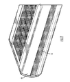
- Figure 1 is a partial upper perspective view of a luminaire including a light pipe structure in accordance with a first embodiment
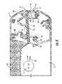
- Figure 2 is a schematic cross-sectional view of the luminaire and light pipe structure of Figure 1 ;
- Figure 3 is a partial schematic cross-sectional view of the luminaire and light pipe structure of Figure 1 ;
- Figure 3a is a partial schematic cross-sectional view of the light pipe structure of Figure 1 ;
- Figure 4 is a schematic cross-sectional view of a luminaire including a light pipe structure in accordance with another embodiment.
- Figure 4a is a partial schematic cross-sectional view of the light pipe structure of Figure 4 .
- the luminaire 10 configured for pipe lighting is illustrated.
- the luminaire 10 includes upper and lower light apertures 12 (which may be configured to house any known baffle assemblies) and a light pipe aperture 14. As is shown in the Figures, these apertures are disposed such that light will exit the housing in relatively perpendicular directions.
- the luminaire also includes at least one light source 16, such as a tubular lamp or a compact twin-tube lamp. Extending from an interior area of the housing 12 is a light pipe structure 18, which will be discussed in greater detail hereinbelow.
- the light pipe structure 18 includes a light entry end 20 associated with a visible end 22 via a pipe body 24.
- An entirety of this pipe structure 18 may be constructed of light transmissive materials such as but not limited to plastic or glass.
- the light entry end 20 is disposed in closer proximity to the light source 16 than the visible end 22. This disposal obviously facilitates entry of light from the light source 16 at the light entry end 20.
- light rays 25 from the light source 16 enters the pipe structure 18 at two distinct light entry surfaces 26 and 28.
- the first light entry surface 26 is disposed at the light entry end 20, and runs perpendicular to a relative horizontal axis or centerline 30 of the pipe body 24.
- the second light entry surface 28 is disposed at an angle to (i.e. not parallel or perpendicular to) the centerline 30.
- the first entry surface 26 in disposed in closer proximity to the light source 16 than the light entry surface 28. The distance between these entry surfaces combine with the angle at which they are disposed to define an accessory surface 32 and accessory notch 34 that are configured to associate the pipe structure 18 with luminaire accessories such as but not limited to lenses and modifiers.
- This visible end 22 includes a relatively upper extension 36 and a relatively lower extension 38.
- the pipe structure 18 is disposed such that the upper extension 36 abuts a relatively upper extent 40 of the light pipe aperture 14.
- the lower extension 38 abuts an opposite, relatively lower extent 42 of the light pipe aperture 14 in this embodiment.
- this visible surface 44 defines a v-shaped cavity or depression 46 that delimits a separation point between the upper and lower extensions 36 and 38.
- this notch 46 is disposed at a relative midpoint of the visible surface 44 between the relatively upper extent 40 of the light pipe aperture 44 and the relatively lower extent 42 of the light pipe aperture 14.
- the notch 46 is also disposed along a major axis of the visible surface 44 (i.e. along a length extending towards the ends of the luminaire 10), and in alignment with the centerline 30 of the pipe body 24.
- an interior point 50 of the v-shaped notch 46 is disposed in direct alignment with the centerline 30. Aligning the interior point 50 with the centerline 30 aids in preventing an undesirable concentration of light at a throat junction 52 between the pipe body 24 and the visible end 22 (i.e. axial brightness).
- this prevention is accomplished via angling and disposal of depression surfaces or walls 51a and 51b (meeting at the interior point 50) relative to the light pipe body 24 and collimated light rays 25 traveling therethrough.
- These walls 51a and 51b act (at an interior of the pipe 18) to reflect at least a portion the collimated light rays 25 off of a major axis 58 of the light pipe body 24 and into, or in a direction of, extensions 36 and 38.
- the extensions 36 and 38 may be beneficial for the extensions 36 and 38 to include a curved, visible surface profile, such as that shown in the Figure.
- the visible end 22 and a portion of the pipe body 24 are illustrated to include rib structures 54.
- These rib structures 54 are disposed at interior surfaces 56 and 58 of the extensions 36 and 38 (the interior surfaces 56 and 58 being disposed opposite the visible surface 44) and along the pipe body 24 in proximity to the extensions 36 and 38.
- the notch 46 facilitates activation of these rib structures 54 when light is flowing therethrough, causing light rays to exit the relatively smooth visible surface 44 in a manner that creates a unique stepped highlight effect.
- These ribs act to extract or otherwise cause some of the light to exit in the same general direction as the collimated light but at a distance/offset from the projected dimension of the major axis 58 of the light pipe body 24.
- disposal of these ribbed structures 54 along the light pipe structure 18 renders any secondary etching or frosting processes to be unnecessary.
- association extensions 56 are configured to engage with various internal luminaire flanges 58 in a manner that associates and supports the light pipe structure 18 within the luminaire housing 12.
- a single extension 70 defines the visible surface 44, with an angled surface 72 being disposed at a junction between the light pipe body 24 and the extension 70.
- the angled surface 72 is disposed at an angle relative to the light pipe body 24 and collimated light rays 25 traveling therethrough. The angle is away from both parallel and perpendicular orientation relative to both the light pipe body 24 and extension 70
- This surface 72 acts (at an interior of the pipe 18) to reflect at least a portion the collimated light rays 25 off of a major axis 58 of the light pipe body 24 and into, or in a direction of, extension 70.
- the structure 18 of Figure 4 also includes rib structures 54 disposed at an interior surface 78 of the extension 70.
Landscapes
- Engineering & Computer Science (AREA)
- General Engineering & Computer Science (AREA)
- Non-Portable Lighting Devices Or Systems Thereof (AREA)
- Wind Motors (AREA)
- Light Guides In General And Applications Therefor (AREA)
Applications Claiming Priority (1)
| Application Number | Priority Date | Filing Date | Title |
|---|---|---|---|
| US16183509P | 2009-03-20 | 2009-03-20 |
Publications (2)
| Publication Number | Publication Date |
|---|---|
| EP2230447A2 true EP2230447A2 (fr) | 2010-09-22 |
| EP2230447A3 EP2230447A3 (fr) | 2013-04-03 |
Family
ID=42320194
Family Applications (2)
| Application Number | Title | Priority Date | Filing Date |
|---|---|---|---|
| EP10157104A Withdrawn EP2230447A3 (fr) | 2009-03-20 | 2010-03-19 | Structure de conducteur de lumière et luminaire doté de la structure de conducteur de lumière |
| EP10157115.6A Withdrawn EP2233830A3 (fr) | 2009-03-20 | 2010-03-19 | Déflecteur produisant une lumière asymétrique et luminaire comprenant un tel déflecteur |
Family Applications After (1)
| Application Number | Title | Priority Date | Filing Date |
|---|---|---|---|
| EP10157115.6A Withdrawn EP2233830A3 (fr) | 2009-03-20 | 2010-03-19 | Déflecteur produisant une lumière asymétrique et luminaire comprenant un tel déflecteur |
Country Status (3)
| Country | Link |
|---|---|
| US (2) | US20100238661A1 (fr) |
| EP (2) | EP2230447A3 (fr) |
| CA (2) | CA2697336A1 (fr) |
Families Citing this family (33)
| Publication number | Priority date | Publication date | Assignee | Title |
|---|---|---|---|---|
| US9335038B2 (en) | 2011-07-20 | 2016-05-10 | Ip Holdings, Llc | Vertically disposed HID lamp fixture |
| USD770079S1 (en) | 2015-04-02 | 2016-10-25 | Ip Holdings, Llc | Light fixture |
| USD698986S1 (en) | 2013-03-27 | 2014-02-04 | Ip Holdings, Llc | Horticulture grow light housing |
| USD698987S1 (en) | 2013-06-20 | 2014-02-04 | Ip Holdings, Llc | Horticulture grow light housing |
| USD745993S1 (en) | 2013-07-09 | 2015-12-22 | Ip Holdings, Llc | Horticulture grow light housing |
| US9016907B2 (en) | 2013-07-18 | 2015-04-28 | Ip Holdings, Llc | Air cooled horticulture lighting fixture for a double ended high pressure sodium lamp |
| USD748849S1 (en) | 2014-06-11 | 2016-02-02 | Ip Holdings, Llc | Sealed optics air cooled grow light |
| US9750199B2 (en) | 2013-07-18 | 2017-09-05 | Ip Holdings, Llc | Air cooled horticulture lighting fixture |
| USD731701S1 (en) | 2014-02-24 | 2015-06-09 | Ip Holdings, Llc | Horticulture grow light housing |
| USD750312S1 (en) * | 2014-08-07 | 2016-02-23 | Ip Holdings, Llc | Horticulture grow light |
| USD732235S1 (en) | 2014-08-07 | 2015-06-16 | Ip Holdings, Llc | Horticulture grow light |
| USD732236S1 (en) | 2014-09-11 | 2015-06-16 | Ip Holdings, Llc | Light fixture |
| USD747029S1 (en) | 2014-10-22 | 2016-01-05 | Ip Holdings, Llc | Horticulture grow light |
| USD751245S1 (en) | 2014-12-11 | 2016-03-08 | Ip Holdings, Llc | Horticulture grow light |
| USD757346S1 (en) | 2015-01-08 | 2016-05-24 | Ip Holdings, Llc | Horticulture grow light |
| USD773107S1 (en) | 2015-04-13 | 2016-11-29 | Ip Holdings, Llc | Horticulture grow light |
| USD769513S1 (en) | 2015-04-15 | 2016-10-18 | Ip Holdings, Llc | Light fixture |
| USD770670S1 (en) | 2015-06-24 | 2016-11-01 | Ip Holdings, Llc | Horticulture grow light |
| USD780985S1 (en) | 2016-01-05 | 2017-03-07 | Ip Holdings, Llc | Light fixture |
| USD780986S1 (en) | 2016-01-07 | 2017-03-07 | Ip Holdings, Llc | Light fixture |
| USD796728S1 (en) | 2016-06-06 | 2017-09-05 | Ip Holdings, Llc | Light fixture |
| USD804079S1 (en) | 2016-08-31 | 2017-11-28 | Ip Holdings, Llc | Light fixture |
| USD804078S1 (en) | 2016-08-31 | 2017-11-28 | Ip Holdings, Llc | Light fixture |
| USD797350S1 (en) | 2016-11-01 | 2017-09-12 | Ip Holdings, Llc | Light fixture |
| USD822882S1 (en) | 2017-05-17 | 2018-07-10 | Ip Holdings, Llc | Horticulture grow light |
| CN107166219B (zh) * | 2017-06-21 | 2023-05-02 | 欧普照明股份有限公司 | 一种台灯 |
| USD843049S1 (en) | 2017-09-14 | 2019-03-12 | Hgci, Inc. | Horticulture grow light |
| EP3480415B1 (fr) | 2017-10-09 | 2024-08-28 | Hunter Douglas, Inc. | Ensembles de rail supérieur pour revêtements architecturaux et procédés associés |
| USD842532S1 (en) | 2017-10-25 | 2019-03-05 | Hgci, Inc. | Light fixture |
| USD871654S1 (en) | 2017-10-30 | 2019-12-31 | Hgci, Inc. | Light fixture |
| USD848663S1 (en) | 2017-11-03 | 2019-05-14 | Hgci, Inc. | Light fixture |
| USD848664S1 (en) | 2017-11-07 | 2019-05-14 | Hgci, Inc. | Light fixture |
| USD848665S1 (en) | 2017-11-08 | 2019-05-14 | Hgci, Inc. | Horticulture grow light |
Family Cites Families (23)
| Publication number | Priority date | Publication date | Assignee | Title |
|---|---|---|---|---|
| US2971083A (en) * | 1958-11-14 | 1961-02-07 | Gen Electric | Low brightness louver |
| US3389246A (en) * | 1966-01-17 | 1968-06-18 | Sylvan R. Shemitz | Illuminated wall partition divider |
| DE1622846A1 (de) * | 1967-03-29 | 1970-11-26 | Elek Ska Ab Exaktor | Asymmetrischer Beleuchtungsschirm |
| US4054793A (en) * | 1973-08-22 | 1977-10-18 | Sylvan R. Shemitz Associates, Inc. | Lighting system |
| AT376784B (de) * | 1982-01-18 | 1984-12-27 | Zumtobel Ag | Arbeitsplatzleuchte |
| US4414609A (en) * | 1982-10-08 | 1983-11-08 | Sylvan R. Shemitz And Associates, Inc. | Luminaire for a visual display terminal |
| DE3412162C1 (de) * | 1984-03-31 | 1985-08-29 | Trilux-Lenze Gmbh + Co Kg, 5760 Arnsberg | Langgestreckte Leuchte |
| US5008791A (en) * | 1990-07-19 | 1991-04-16 | Caferro Ronald N | Low direct glare and wall wash parabolic lighting grid |
| US5207498A (en) | 1991-08-27 | 1993-05-04 | Electrolux Corporation | Vacuum cleaner headlight |
| DE4413070A1 (de) * | 1994-04-15 | 1995-10-19 | Thorn Licht Gmbh | Arbeitsplatzleuchte |
| DE19529054A1 (de) * | 1995-07-31 | 1997-02-06 | Semperlux Gmbh | Selbstleuchtende Gehäuseflächen von Leuchten mit Hilfe der Einleitung von Licht |
| US5678922A (en) * | 1995-08-16 | 1997-10-21 | H. E. Williams, Inc. | Lighting fixture and anodized metallic louver system therefor |
| US5528478A (en) * | 1995-10-04 | 1996-06-18 | Cooper Industries, Inc. | Lighting fixture having a parabolic louver |
| DE19547861A1 (de) * | 1995-12-21 | 1997-06-26 | Reitter & Schefenacker Gmbh | Rückleuchte für Fahrzeuge, vorzugsweise Kraftfahrzeuge |
| DE69803297T2 (de) * | 1997-08-12 | 2002-08-22 | Breault Res Organization Inc | Doppelreflektierende linse |
| US6733166B2 (en) * | 1997-12-09 | 2004-05-11 | Federal -Mogul World Wide, Inc. | Illuminated interior article system utilizing a Y-branch waveguide |
| US6161939A (en) * | 1999-05-05 | 2000-12-19 | Semperlux Ag | Interior lighting fixture |
| DE19943589A1 (de) * | 1999-09-11 | 2001-04-05 | Preh Elektro Feinmechanik | Lichtleiterpilz |
| ITFI20020077U1 (it) * | 2002-07-19 | 2004-01-19 | Targetti Sankey Spa | Griglia antiabbagliamento per sorgenti luminose tubolari |
| DE20312268U1 (de) * | 2003-08-08 | 2003-12-04 | Grimm, Manfred | Arbeitsplatzleuchte |
| US7443591B1 (en) * | 2007-02-01 | 2008-10-28 | The Boeing Company | Homogenizing optical beam combiner |
| DE102007013082A1 (de) * | 2007-03-14 | 2008-09-18 | Hella Kgaa Hueck & Co. | Signalleuchte |
| GB2449262B (en) * | 2007-05-14 | 2011-08-24 | Visteon Global Tech Inc | Illumination system |
-
2010
- 2010-03-18 US US12/727,069 patent/US20100238661A1/en not_active Abandoned
- 2010-03-18 US US12/727,090 patent/US8297819B2/en not_active Expired - Fee Related
- 2010-03-19 CA CA2697336A patent/CA2697336A1/fr not_active Abandoned
- 2010-03-19 CA CA2697217A patent/CA2697217A1/fr not_active Abandoned
- 2010-03-19 EP EP10157104A patent/EP2230447A3/fr not_active Withdrawn
- 2010-03-19 EP EP10157115.6A patent/EP2233830A3/fr not_active Withdrawn
Non-Patent Citations (1)
| Title |
|---|
| None |
Also Published As
| Publication number | Publication date |
|---|---|
| US20100238679A1 (en) | 2010-09-23 |
| CA2697336A1 (fr) | 2010-09-20 |
| US8297819B2 (en) | 2012-10-30 |
| EP2233830A3 (fr) | 2013-04-24 |
| US20100238661A1 (en) | 2010-09-23 |
| EP2233830A2 (fr) | 2010-09-29 |
| EP2230447A3 (fr) | 2013-04-03 |
| CA2697217A1 (fr) | 2010-09-20 |
Similar Documents
| Publication | Publication Date | Title |
|---|---|---|
| US8297819B2 (en) | Light pipe structure and luminaire with light pipe structure | |
| US6474859B2 (en) | Illuminated looped light pipe | |
| JP2005193892A (ja) | 自動車用の信号または照明装置 | |
| MA33143B1 (fr) | Illuminateur a guide de lumiere annulaire et dispositif de balayage optique | |
| CN105556203A (zh) | 照明装置 | |
| ATE515067T1 (de) | Beleuchtungssystem | |
| DE502006003613D1 (de) | Led-beleuchtungsmodul | |
| WO2006002146A3 (fr) | Lampe a plasma avec guide d'onde de transmission de lumiere | |
| US20170241616A1 (en) | Vehicle lighting fixture | |
| WO2006113664A3 (fr) | Luminaire compact d'ambiance et de travail, a lampe a deux tubes | |
| WO2008024733A2 (fr) | Luminaire à fibre optique émettant des motifs d'extraction de lumière latérale diffusant et spéculaire | |
| DE502004011663D1 (de) | Leuchte für ein fahrzeug | |
| NZ547869A (en) | Recessed lighting fixture | |
| JP2015191775A (ja) | 車両用灯具 | |
| US6769799B2 (en) | Apparatus, methods and articles of manufacture for a co-extruded light pipe | |
| EP1207337A3 (fr) | Feu pour véhicule | |
| EP1134484A3 (fr) | Dispositif d' éclairage à usage multiple | |
| ES2821601B2 (es) | Difusor de aire para vehiculos automoviles | |
| WO2008120148A3 (fr) | Système d'éclairage général et luminaire | |
| WO2013140337A1 (fr) | Mélange de lumière le long d'un trajet annulaire | |
| EP1584864A3 (fr) | Réflecteur pour une lumière avec un élément réglable et une lumière comprenant un tel réflecteur | |
| JPH11117483A (ja) | 照明付き手摺 | |
| EP1679470A3 (fr) | Luminaire avec guide de lumière creux | |
| JP2001059391A (ja) | 足元灯ユニットおよび足元灯付門扉 | |
| US10338299B2 (en) | Lighting system using a lightguide |
Legal Events
| Date | Code | Title | Description |
|---|---|---|---|
| PUAI | Public reference made under article 153(3) epc to a published international application that has entered the european phase |
Free format text: ORIGINAL CODE: 0009012 |
|
| AK | Designated contracting states |
Kind code of ref document: A2 Designated state(s): AT BE BG CH CY CZ DE DK EE ES FI FR GB GR HR HU IE IS IT LI LT LU LV MC MK MT NL NO PL PT RO SE SI SK SM TR |
|
| AX | Request for extension of the european patent |
Extension state: AL BA ME RS |
|
| PUAL | Search report despatched |
Free format text: ORIGINAL CODE: 0009013 |
|
| AK | Designated contracting states |
Kind code of ref document: A3 Designated state(s): AT BE BG CH CY CZ DE DK EE ES FI FR GB GR HR HU IE IS IT LI LT LU LV MC MK MT NL NO PL PT RO SE SI SK SM TR |
|
| AX | Request for extension of the european patent |
Extension state: AL BA ME RS |
|
| RIC1 | Information provided on ipc code assigned before grant |
Ipc: F21V 8/00 20060101AFI20130222BHEP Ipc: F21V 7/00 20060101ALI20130222BHEP Ipc: F21S 8/04 20060101ALI20130222BHEP |
|
| STAA | Information on the status of an ep patent application or granted ep patent |
Free format text: STATUS: THE APPLICATION IS DEEMED TO BE WITHDRAWN |
|
| 18D | Application deemed to be withdrawn |
Effective date: 20131001 |