EP2230460A2 - Motifs d'allumage de clapet d'aération rotatif pour désaccord de résonance - Google Patents
Motifs d'allumage de clapet d'aération rotatif pour désaccord de résonance Download PDFInfo
- Publication number
- EP2230460A2 EP2230460A2 EP10156639A EP10156639A EP2230460A2 EP 2230460 A2 EP2230460 A2 EP 2230460A2 EP 10156639 A EP10156639 A EP 10156639A EP 10156639 A EP10156639 A EP 10156639A EP 2230460 A2 EP2230460 A2 EP 2230460A2
- Authority
- EP
- European Patent Office
- Prior art keywords
- engine
- pulse detonation
- pdcs
- detonation combustors
- inlet ports
- Prior art date
- Legal status (The legal status is an assumption and is not a legal conclusion. Google has not performed a legal analysis and makes no representation as to the accuracy of the status listed.)
- Withdrawn
Links
- 238000010304 firing Methods 0.000 title description 30
- 238000005474 detonation Methods 0.000 claims abstract description 62
- 239000000446 fuel Substances 0.000 description 4
- 238000000034 method Methods 0.000 description 3
- 238000004200 deflagration Methods 0.000 description 2
- 239000000203 mixture Substances 0.000 description 2
- 238000002485 combustion reaction Methods 0.000 description 1
- 230000003247 decreasing effect Effects 0.000 description 1
- 230000004048 modification Effects 0.000 description 1
- 238000012986 modification Methods 0.000 description 1
- 239000007800 oxidant agent Substances 0.000 description 1
- 238000010248 power generation Methods 0.000 description 1
- VEMKTZHHVJILDY-UHFFFAOYSA-N resmethrin Chemical compound CC1(C)C(C=C(C)C)C1C(=O)OCC1=COC(CC=2C=CC=CC=2)=C1 VEMKTZHHVJILDY-UHFFFAOYSA-N 0.000 description 1
- 238000012163 sequencing technique Methods 0.000 description 1
- 230000035939 shock Effects 0.000 description 1
- 238000011144 upstream manufacturing Methods 0.000 description 1
Images


Classifications
-
- F—MECHANICAL ENGINEERING; LIGHTING; HEATING; WEAPONS; BLASTING
- F23—COMBUSTION APPARATUS; COMBUSTION PROCESSES
- F23R—GENERATING COMBUSTION PRODUCTS OF HIGH PRESSURE OR HIGH VELOCITY, e.g. GAS-TURBINE COMBUSTION CHAMBERS
- F23R7/00—Intermittent or explosive combustion chambers
-
- F—MECHANICAL ENGINEERING; LIGHTING; HEATING; WEAPONS; BLASTING
- F23—COMBUSTION APPARATUS; COMBUSTION PROCESSES
- F23R—GENERATING COMBUSTION PRODUCTS OF HIGH PRESSURE OR HIGH VELOCITY, e.g. GAS-TURBINE COMBUSTION CHAMBERS
- F23R2900/00—Special features of, or arrangements for continuous combustion chambers; Combustion processes therefor
- F23R2900/00013—Reducing thermo-acoustic vibrations by active means
Definitions
- This invention relates to pulse detonation systems, and more particularly, rotary air valve firing patterns for resonance detuning.
- PDCs pulse detonation combustors
- PDEs engines
- the sequential firing of multiple PDCs can result in creating resonance in downstream components of an engine.
- the creation of this resonance can result in high cycle fatigue failure in downstream components.
- this can create large flow asymmetries can lead to losses downstream as the flow passes through nozzles, etc.
- force loading on downstream components can be asymmetric, thus requiring additional structure and weight to compensate for this loading.
- an engine contains a plurality of pulse detonation combustors and a rotary inlet valve structure having a plurality of inlet ports through which at least air flows to enter the plurality of pulse detonation combustors during operation of said engine.
- the ratio of the pulse detonation combustors to the inlet ports is a non-integer.
- a pulse detonation combustor PDC (also including PDEs) is understood to mean any device or system that produces both a pressure rise and velocity increase from a series of repeating detonations or quasi-detonations within the device.
- a "quasi-detonation” is a supersonic turbulent combustion process that produces a pressure rise and velocity increase higher than the pressure rise and velocity increase produced by a deflagration wave.
- Embodiments of PDCs (and PDEs) include a means of igniting a fuel/oxidizer mixture, for example a fuel/air mixture, and a detonation chamber, in which pressure wave fronts initiated by the ignition process coalesce to produce a detonation wave.
- Each detonation or quasi-detonation is initiated either by external ignition, such as spark discharge or laser pulse, or by gas dynamic processes, such as shock focusing, auto ignition or by another detonation (i.e. cross-fire).
- engine means any device used to generate thrust and/or power.
- FIG. 1 depicts an engine 100 in accordance with an embodiment of the present invention.
- the engine 100 contains a compressor stage 101, a plurality of PDCs 103 and a turbine stage 111.
- Each of the compressor stage 101, the PDCs 103 and turbine stage 111 can have a conventional and known structure and configuration.
- the various embodiments of the present invention are not limited in this regard.
- Coupled to the PDCs are nozzles 109 which direct the flow from the PDCs 103 into the turbine stage 111.
- the nozzles 109 diverging.
- the nozzles 109 can be of the converging or converging-diverging type.
- each PDC 103 is coupled to its own nozzle 109.
- the present invention is not limited to this specific embodiment as it is contemplated that a single nozzle, plenum and/or manifold structure can be used to direct the flow from the plurality of PDCs to the turbine 111.
- an inlet system 107 which comprises an inlet valve structure 105.
- the inlet valve structure 105 is a rotating valve structure which has a plurality of inlet ports 104 to allow the flow from the compressor stage 101 to enter the PDCs 103 for PDC operation.
- the inlet system 107 may contain a plenum structure and/or drive mechanism to facilitate flow from the compressor stage 101 to the PDCs 103 and drive the inlet valve structure 105.
- the present invention is not limited by the specific configuration and/or implementation of the inlet system 107, as conventional known and used systems can be employed to implement the various embodiments of the present invention discussed in more detail below.
- FIGs. 2 through 5 various embodiments of the present invention are depicted.
- non-sequential PDC firing patterns are employed to decouple the natural modes of the PDC system from the resonance modes of downstream components, such as the turbine stage 111.
- embodiments of the present invention employ an inlet valve structure 105 which has a rotary configuration and a plurality of inlet ports 104 to allow the flow of air and/or fuel into the PDCs 103 for PDC operation.
- the ratio of PDCs 103 to inlet ports 104 is a non-integer.
- the firing sequence of PDCs is either a counter-sequential firing pattern (i.e., sequential in the opposite direction of valve rotation) or a skip firing pattern in which adjacent PDCs 103 are skipped during the firing sequence.
- skip patterns the firing pattern is in the same direction as the valve rotation.
- valve structure 105 is depicted as a disk-like air inlet valve, the present invention is not limited to this specific embodiment, although it can be used.
- Various embodiments of the present invention can use other types of rotating valve geometries and configurations where one or more ports or inlets of the inlet valve structure engage or otherwise coupled with PDC tubes arrange in an annulus type configuration.
- a flat disk is shown as the valve structure 105, various embodiments of the present invention are not limited to this configuration.
- the valve structure 105 rotates about a central axis which is coincident with a central axis of a grouping of PDCs 103 arranged in an annulus type pattern.
- the valve structure 105 contains a plurality of inlet ports 104. This can be seen in each of FIGs. 2 through 5 .
- the inlet ports 104 "engage" with PDCs 103 to allow air/fuel flow from upstream of the valve structure 105 (such as from the compressor stage 101) through the ports 104 and into the PDCs 103.
- the structure 105 rotates each of the ports 104 becomes engaged with PDCs 103 during the rotation.
- the embodiment shown in FIG. 2 has a non-integer tube/port ratio. That is the embodiment shown is a 5/2 configuration - having 5 PDCs to 2 inlet ports. Therefore, the ratio is 2.5. The operation of this embodiment will now be described.
- each of the PDCs 103 has been identified with a number (1, 2, 3, 4 and 5), and the structure 105 is rotating in a counter-clockwise direction.
- the upper most port 104 is engaged with the #1 PDC 103, thus allowing the #1 PDC to fill, as required for PDC operation.
- the structure 105 continues to rotate the bottom port 104 engages with the #4 PDC 103 to allow this PDC.
- the #1 PDC is fired (i.e., detonated), and once the #4 PDC 103 is filled and the port 104 moves on the #4 PDC 103 is detonated.
- this sequencing is repeated as the structure 105 rotates, thus causing non-adjacent PDCs to fire, resulting in resonant detuning.
- the filling pattern of the PDCs 103 is #1, 4, 2, 5, 3, 1, ... while the detonation pattern or sequence will be #3, 1, 4, 2, 5, 3, ... This resultant firing pattern ensures that non adjacent PDCs 103 are fired in sequence.
- FIG. 2 shows five PDCs 103 being employed, this number can be decreased to three or increased so long as the ratio remains a non-integer (e.g., 7, 9, etc.).
- ports 104 are shown as having a circular opening, it is contemplated that the shape of the opening can be changed to optimize flow into the PDCs 103. Further, the location and positioning of the ports 104 on the structure 105 can be optimized from what is shown (180 degrees from each other) to implement the desired performance. Additionally, although the rotation of the structure 105 is shown as counter-clockwise, the rotation can be reversed.
- FIG. 3 an additional embodiment 300 is shown.
- the tube-to-port ratio is 1.33.
- the filling sequence of the PDCs 103 is #1, 4, 3, 2, 1, 4... and the firing sequence is 2, 1, 4, 3, 2, 1, ... Therefore, this embodiment provides a counter-sequential firing pattern. That is the firing pattern or sequence of the PDCs 103 rotates in a direction opposite of rotation of the structure 105.
- the FIG. 4 embodiment 400 is similar to the embodiment shown in FIG. 2 except the tube-to-port ratio is 1.67 because there are five PDCs 103 and three ports 104.
- the filling sequence of the PDCs 103 is #1, 3, 5, 2, 4, 1... and the firing sequence is 4, 1, 3, 5, 2, 4, ... Therefore, this embodiment provides a star firing pattern. That is, the firing pattern or sequence of the PDCs 103 creates a star pattern, and no adjacent PDCs 103 are detonated sequentially.
- the FIG. 5 embodiment 500 shows an embodiment having a ratio of 2.67.
- the filling sequence of the PDCs 103 is #1, 4, 7, 2, 5, 8, 3, 6, 1... and the firing sequence is 6, 1, 4, 7, 2, 5, 8, 3, 6, ... Therefore, this embodiment provides a co-rotating star firing pattern. That is, the firing pattern or sequence of the PDCs 103 creates a star pattern (no adjacent PDCs 103 are detonated sequentially) and the firing sequence rotates in the same direction as the structure 105.
- the present invention contemplates many other embodiments in which the ratio of PDCs 103 to ports 104 is a non-integer.
- the Table below shows additional contemplated embodiments of the present invention.
- the present invention is not limited to the above additional exemplary embodiments of the present invention, but they are intended to demonstrate additional exemplary embodiments.
- the present invention contemplates a PDC-to-port ratio of between 1 and 4 when the ratio is a non-integer.
- the present invention is not limited to embodiments where only a single PDC 103 is fired/detonated at one time.
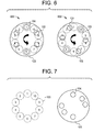
- various embodiments of the present invention have two or more PDCs 103 which are fired/detonated simultaneously. On such embodiment is shown in FIG. 6 .
- FIG. 6 embodiment 600 there are ten PDCs 103 (#1 through 10) and six ports 104.
- the structure 105 rotates two PDCs 103 fill at the same time and two PDCs 103 detonate at the same time. This is because two ports 104 engage with PDCs 103 at the same time. This can be seen in the figures of FIG. 6 .
- this embodiment provides a symmetrical loading relative to a centerline of embodiment 600.
- the filling sequence is 1-6, 4-9, 2-8, 5-10, 3-7, 1-6, ...
- the firing sequence of the PDCs 103 is 3-7, 1-6, 4-9, 2-8, 5-10, 3-7, ... (It is noted that for each PDC pairs shown - e.g., "1-6" - this means that PDCs #1 and #6 are filled or fired at the same time.
- This embodiment provides a counter-rotational firing sequence where every other PDC 103 is filled/fired.
- the ports 104 and/or the PDCs 103 can be distributed asymmetrically to achieved a desired performance or resonance detuning.
- the PDCs 103 and ports 104 are distributed in an annulus fashion such that the angle between any two adjacent ports 104 or PDCs 103 is the same.
- the angle between any two adjacent ports 104 and/or PDCs 103 is different than another angle between any two other adjacent ports 104 and/or PDCs 103.
- This embodiment is simplistically shown in FIG. 7 in which the inlet valve structure 105 is shown with asymmetrically distributed ports 104 and the PDCs 103 are distributed symmetrically. It is noted that the structure 105 is shown separately from the grouping of the PDCs 103 for clarity.
- the PDCs 103 can be distributed asymmetrically while the ports 104 are symmetrical, or both the ports 104 and PDCs 103 are distributed asymmetrically.
- a different number of PDCs 103 will be detonated at different times, contrary to the embodiments discussed above regarding FIGs. 2-6 . That is, in the embodiment shown in FIG. 7 , it is contemplated that the firing sequence of the PDCs 103 will be (4-5-9-10), (1-6), (3-4-8-9), (5-10), (2-3-7-8), ....
- the firing of PDCs 103 will alternate between four PDCs 103 and two PDCs 103. Therefore, if such performance was desired, it can be achieved with an embodiment similar to that shown in FIG. 7 .
- the present invention has been discussed above specifically with respect to aircraft and power generation applications, the present invention is not limited to this and can be in any similar detonation/deflagration device in which the benefits of the present invention are desirable.
Landscapes
- Engineering & Computer Science (AREA)
- Chemical & Material Sciences (AREA)
- Combustion & Propulsion (AREA)
- Mechanical Engineering (AREA)
- General Engineering & Computer Science (AREA)
- Fluidized-Bed Combustion And Resonant Combustion (AREA)
- Multiple-Way Valves (AREA)
Applications Claiming Priority (1)
| Application Number | Priority Date | Filing Date | Title |
|---|---|---|---|
| US12/407,309 US8341932B2 (en) | 2009-03-19 | 2009-03-19 | Rotary air valve firing patterns for resonance detuning |
Publications (2)
| Publication Number | Publication Date |
|---|---|
| EP2230460A2 true EP2230460A2 (fr) | 2010-09-22 |
| EP2230460A3 EP2230460A3 (fr) | 2014-12-31 |
Family
ID=42269528
Family Applications (1)
| Application Number | Title | Priority Date | Filing Date |
|---|---|---|---|
| EP10156639.6A Withdrawn EP2230460A3 (fr) | 2009-03-19 | 2010-03-16 | Motifs d'allumage de clapet d'aération rotatif pour désaccord de résonance |
Country Status (4)
| Country | Link |
|---|---|
| US (1) | US8341932B2 (fr) |
| EP (1) | EP2230460A3 (fr) |
| JP (1) | JP5576683B2 (fr) |
| CA (1) | CA2696289A1 (fr) |
Families Citing this family (14)
| Publication number | Priority date | Publication date | Assignee | Title |
|---|---|---|---|---|
| US20140083111A1 (en) * | 2012-09-25 | 2014-03-27 | United Technologies Corporation | Gas turbine asymmetric fuel nozzle combustor |
| US9709279B2 (en) | 2014-02-27 | 2017-07-18 | General Electric Company | System and method for control of combustion dynamics in combustion system |
| US9709278B2 (en) | 2014-03-12 | 2017-07-18 | General Electric Company | System and method for control of combustion dynamics in combustion system |
| US9644846B2 (en) * | 2014-04-08 | 2017-05-09 | General Electric Company | Systems and methods for control of combustion dynamics and modal coupling in gas turbine engine |
| US9845956B2 (en) | 2014-04-09 | 2017-12-19 | General Electric Company | System and method for control of combustion dynamics in combustion system |
| US9845732B2 (en) | 2014-05-28 | 2017-12-19 | General Electric Company | Systems and methods for variation of injectors for coherence reduction in combustion system |
| US9551283B2 (en) * | 2014-06-26 | 2017-01-24 | General Electric Company | Systems and methods for a fuel pressure oscillation device for reduction of coherence |
| US10113747B2 (en) | 2015-04-15 | 2018-10-30 | General Electric Company | Systems and methods for control of combustion dynamics in combustion system |
| FR3037384B1 (fr) * | 2015-06-11 | 2017-06-23 | Turbomeca | Module de chambre de combustion cvc de turbomachine comportant une prechambre de combustion |
| US20180179952A1 (en) * | 2016-12-23 | 2018-06-28 | General Electric Company | Rotating detonation engine and method of operating same |
| CN106837602B (zh) * | 2017-02-20 | 2018-03-27 | 刘展文 | 小型涡扇发动机 |
| US11674476B2 (en) | 2017-06-09 | 2023-06-13 | General Electric Company | Multiple chamber rotating detonation combustor |
| US11572840B2 (en) | 2019-12-03 | 2023-02-07 | General Electric Company | Multi-mode combustion control for a rotating detonation combustion system |
| CN114963239A (zh) * | 2022-05-12 | 2022-08-30 | 西北工业大学 | 一种分级燃烧的旋转爆震燃烧装置 |
Citations (1)
| Publication number | Priority date | Publication date | Assignee | Title |
|---|---|---|---|---|
| WO2003023206A1 (fr) | 2001-09-07 | 2003-03-20 | Bernard Macarez | Turbine a gaz avec combustion intermittente |
Family Cites Families (10)
| Publication number | Priority date | Publication date | Assignee | Title |
|---|---|---|---|---|
| US2888803A (en) * | 1954-08-30 | 1959-06-02 | Pon Lemuel | Intermittent combustion turbine engine |
| US2928242A (en) * | 1954-12-16 | 1960-03-15 | Phillips Petroleum Co | Multi-combustion chamber gas turbine with rotary valving |
| US6062018A (en) * | 1993-04-14 | 2000-05-16 | Adroit Systems, Inc. | Pulse detonation electrical power generation apparatus with water injection |
| US5345758A (en) * | 1993-04-14 | 1994-09-13 | Adroit Systems, Inc. | Rotary valve multiple combustor pulse detonation engine |
| US5983624A (en) * | 1997-04-21 | 1999-11-16 | Anderson; J. Hilbert | Power plant having a U-shaped combustion chamber with first and second reflecting surfaces |
| US6637187B2 (en) | 2000-09-08 | 2003-10-28 | Techland Research, Inc. | Rotary inlet flow controller for pulse detonation combustion engines |
| US6931833B2 (en) * | 2003-04-30 | 2005-08-23 | United Technologies Corporation | Pulse combustion device |
| US7340903B2 (en) * | 2003-12-24 | 2008-03-11 | Board Of Regents, The University Of Texas System | Scalable power generation using a pulsed detonation engine |
| US20060053801A1 (en) * | 2004-09-15 | 2006-03-16 | Orlando Robert J | Cooling system for gas turbine engine having improved core system |
| US7891164B2 (en) | 2006-10-31 | 2011-02-22 | General Electric Company | Inlet airflow management system for a pulse detonation engine for supersonic applications |
-
2009
- 2009-03-19 US US12/407,309 patent/US8341932B2/en not_active Expired - Fee Related
-
2010
- 2010-03-11 CA CA2696289A patent/CA2696289A1/fr not_active Abandoned
- 2010-03-12 JP JP2010055240A patent/JP5576683B2/ja not_active Expired - Fee Related
- 2010-03-16 EP EP10156639.6A patent/EP2230460A3/fr not_active Withdrawn
Patent Citations (2)
| Publication number | Priority date | Publication date | Assignee | Title |
|---|---|---|---|---|
| WO2003023206A1 (fr) | 2001-09-07 | 2003-03-20 | Bernard Macarez | Turbine a gaz avec combustion intermittente |
| US20040250529A1 (en) | 2001-09-07 | 2004-12-16 | Bernard Macarez | Gas turbine with intermittent combustion |
Non-Patent Citations (1)
| Title |
|---|
| MACAREZ B. ET AL: "PCE*- Pulse Combustion Engine", EUROPEAN FP6-PROPOSAL FP6-511812-1, October 2003 (2003-10-01), pages 1 - 6, XP003029354 |
Also Published As
| Publication number | Publication date |
|---|---|
| EP2230460A3 (fr) | 2014-12-31 |
| US20100236214A1 (en) | 2010-09-23 |
| US8341932B2 (en) | 2013-01-01 |
| CA2696289A1 (fr) | 2010-09-19 |
| JP5576683B2 (ja) | 2014-08-20 |
| JP2010223221A (ja) | 2010-10-07 |
Similar Documents
| Publication | Publication Date | Title |
|---|---|---|
| US8341932B2 (en) | Rotary air valve firing patterns for resonance detuning | |
| CN109028151B (zh) | 多室旋转爆轰燃烧器 | |
| US20090139199A1 (en) | Pulse detonation combustor valve for high temperature and high pressure operation | |
| US7526912B2 (en) | Pulse detonation engines and components thereof | |
| CN109028149B (zh) | 可变几何形状的旋转爆震燃烧器及其操作方法 | |
| CN109028147B (zh) | 环形喉道旋转爆震燃烧器和相应的推进系统 | |
| US8650856B2 (en) | Fluidic deflagration-to-detonation initiation obstacles | |
| US20180231256A1 (en) | Rotating Detonation Combustor | |
| CN109028148B (zh) | 具有流体二极管结构的旋转爆震燃烧器 | |
| CN100507253C (zh) | 一种多管脉冲爆震燃烧室及其起爆方法 | |
| CN112728585B (zh) | 用于旋转爆震燃烧的系统 | |
| US20080155959A1 (en) | Detonation combustor to turbine transition piece for hybrid engine | |
| CA2721530A1 (fr) | Modulateur de poussee dans un moteur a detonation pulsee a chambres de combustion multiples a multi-amorcage | |
| CN109028144A (zh) | 整体涡流旋转爆震推进系统 | |
| US7980056B2 (en) | Methods and apparatus for controlling air flow within a pulse detonation engine | |
| CN116717813A (zh) | 双峰燃烧系统 | |
| CN203771456U (zh) | 燃烧器、支承柱和燃料歧管 | |
| US7093794B2 (en) | Aircraft and detonative engine incorporating pulse detonation engines | |
| US7891164B2 (en) | Inlet airflow management system for a pulse detonation engine for supersonic applications | |
| US7131260B2 (en) | Multiple detonation initiator for frequency multiplied pulsed detonation combustion | |
| CN110529876B (zh) | 旋转爆轰燃烧系统 | |
| US20100242436A1 (en) | Modulation of inlet mass flow and resonance for a multi-tube pulse detonation engine system using phase shifted operation and detuning | |
| US20120192545A1 (en) | Pulse Detonation Combustor Nozzles | |
| US7634904B2 (en) | Methods and apparatus to facilitate generating power from a turbine engine | |
| US11391202B2 (en) | CVC combustion module for aircraft turbomachine comprising sub-assemblies of independent chambers |
Legal Events
| Date | Code | Title | Description |
|---|---|---|---|
| PUAI | Public reference made under article 153(3) epc to a published international application that has entered the european phase |
Free format text: ORIGINAL CODE: 0009012 |
|
| AK | Designated contracting states |
Kind code of ref document: A2 Designated state(s): AT BE BG CH CY CZ DE DK EE ES FI FR GB GR HR HU IE IS IT LI LT LU LV MC MK MT NL NO PL PT RO SE SI SK SM TR |
|
| TPAC | Observations filed by third parties |
Free format text: ORIGINAL CODE: EPIDOSNTIPA |
|
| PUAL | Search report despatched |
Free format text: ORIGINAL CODE: 0009013 |
|
| AK | Designated contracting states |
Kind code of ref document: A3 Designated state(s): AT BE BG CH CY CZ DE DK EE ES FI FR GB GR HR HU IE IS IT LI LT LU LV MC MK MT NL NO PL PT RO SE SI SK SM TR |
|
| RIC1 | Information provided on ipc code assigned before grant |
Ipc: F23R 7/00 20060101AFI20141121BHEP |
|
| 17P | Request for examination filed |
Effective date: 20150630 |
|
| RBV | Designated contracting states (corrected) |
Designated state(s): AT BE BG CH CY CZ DE DK EE ES FI FR GB GR HR HU IE IS IT LI LT LU LV MC MK MT NL NO PL PT RO SE SI SK SM TR |
|
| STAA | Information on the status of an ep patent application or granted ep patent |
Free format text: STATUS: THE APPLICATION IS DEEMED TO BE WITHDRAWN |
|
| 18D | Application deemed to be withdrawn |
Effective date: 20171003 |