EP2231376B1 - Werkzeug und verfahren zum formen von konstrukten - Google Patents
Werkzeug und verfahren zum formen von konstrukten Download PDFInfo
- Publication number
- EP2231376B1 EP2231376B1 EP08870276.6A EP08870276A EP2231376B1 EP 2231376 B1 EP2231376 B1 EP 2231376B1 EP 08870276 A EP08870276 A EP 08870276A EP 2231376 B1 EP2231376 B1 EP 2231376B1
- Authority
- EP
- European Patent Office
- Prior art keywords
- core
- cavity
- blank
- spring
- base
- Prior art date
- Legal status (The legal status is an assumption and is not a legal conclusion. Google has not performed a legal analysis and makes no representation as to the accuracy of the status listed.)
- Not-in-force
Links
- 238000000034 method Methods 0.000 title claims description 23
- 230000006835 compression Effects 0.000 claims description 11
- 238000007906 compression Methods 0.000 claims description 11
- 238000002347 injection Methods 0.000 claims description 9
- 239000007924 injection Substances 0.000 claims description 9
- 230000015572 biosynthetic process Effects 0.000 claims description 8
- 238000003825 pressing Methods 0.000 claims description 5
- 238000001746 injection moulding Methods 0.000 claims description 4
- 239000011347 resin Substances 0.000 claims description 3
- 229920005989 resin Polymers 0.000 claims description 3
- 239000007788 liquid Substances 0.000 claims 1
- 238000010586 diagram Methods 0.000 description 4
- 239000011087 paperboard Substances 0.000 description 4
- 230000008901 benefit Effects 0.000 description 3
- 239000011111 cardboard Substances 0.000 description 3
- 239000000463 material Substances 0.000 description 3
- 230000007246 mechanism Effects 0.000 description 3
- 230000004048 modification Effects 0.000 description 3
- 238000012986 modification Methods 0.000 description 3
- 238000007493 shaping process Methods 0.000 description 3
- 239000004927 clay Substances 0.000 description 2
- 239000011248 coating agent Substances 0.000 description 2
- 238000000576 coating method Methods 0.000 description 2
- 239000012778 molding material Substances 0.000 description 2
- 230000004075 alteration Effects 0.000 description 1
- 230000004888 barrier function Effects 0.000 description 1
- 150000001875 compounds Chemical class 0.000 description 1
- 238000010276 construction Methods 0.000 description 1
- 238000004049 embossing Methods 0.000 description 1
- 239000012530 fluid Substances 0.000 description 1
- 230000003993 interaction Effects 0.000 description 1
- 238000004519 manufacturing process Methods 0.000 description 1
- 239000000123 paper Substances 0.000 description 1
- 230000008569 process Effects 0.000 description 1
- 239000002966 varnish Substances 0.000 description 1
Images

Classifications
-
- B—PERFORMING OPERATIONS; TRANSPORTING
- B29—WORKING OF PLASTICS; WORKING OF SUBSTANCES IN A PLASTIC STATE IN GENERAL
- B29C—SHAPING OR JOINING OF PLASTICS; SHAPING OF MATERIAL IN A PLASTIC STATE, NOT OTHERWISE PROVIDED FOR; AFTER-TREATMENT OF THE SHAPED PRODUCTS, e.g. REPAIRING
- B29C43/00—Compression moulding, i.e. applying external pressure to flow the moulding material; Apparatus therefor
- B29C43/32—Component parts, details or accessories; Auxiliary operations
- B29C43/36—Moulds for making articles of definite length, i.e. discrete articles
-
- B—PERFORMING OPERATIONS; TRANSPORTING
- B29—WORKING OF PLASTICS; WORKING OF SUBSTANCES IN A PLASTIC STATE IN GENERAL
- B29C—SHAPING OR JOINING OF PLASTICS; SHAPING OF MATERIAL IN A PLASTIC STATE, NOT OTHERWISE PROVIDED FOR; AFTER-TREATMENT OF THE SHAPED PRODUCTS, e.g. REPAIRING
- B29C45/00—Injection moulding, i.e. forcing the required volume of moulding material through a nozzle into a closed mould; Apparatus therefor
- B29C45/14—Injection moulding, i.e. forcing the required volume of moulding material through a nozzle into a closed mould; Apparatus therefor incorporating preformed parts or layers, e.g. injection moulding around inserts or for coating articles
- B29C45/1418—Injection moulding, i.e. forcing the required volume of moulding material through a nozzle into a closed mould; Apparatus therefor incorporating preformed parts or layers, e.g. injection moulding around inserts or for coating articles the inserts being deformed or preformed, e.g. by the injection pressure
-
- B—PERFORMING OPERATIONS; TRANSPORTING
- B29—WORKING OF PLASTICS; WORKING OF SUBSTANCES IN A PLASTIC STATE IN GENERAL
- B29C—SHAPING OR JOINING OF PLASTICS; SHAPING OF MATERIAL IN A PLASTIC STATE, NOT OTHERWISE PROVIDED FOR; AFTER-TREATMENT OF THE SHAPED PRODUCTS, e.g. REPAIRING
- B29C45/00—Injection moulding, i.e. forcing the required volume of moulding material through a nozzle into a closed mould; Apparatus therefor
- B29C45/14—Injection moulding, i.e. forcing the required volume of moulding material through a nozzle into a closed mould; Apparatus therefor incorporating preformed parts or layers, e.g. injection moulding around inserts or for coating articles
- B29C45/14467—Joining articles or parts of a single article
- B29C45/14475—Joining juxtaposed parts of a single article, e.g. edges of a folded container blank
-
- B—PERFORMING OPERATIONS; TRANSPORTING
- B31—MAKING ARTICLES OF PAPER, CARDBOARD OR MATERIAL WORKED IN A MANNER ANALOGOUS TO PAPER; WORKING PAPER, CARDBOARD OR MATERIAL WORKED IN A MANNER ANALOGOUS TO PAPER
- B31B—MAKING CONTAINERS OF PAPER, CARDBOARD OR MATERIAL WORKED IN A MANNER ANALOGOUS TO PAPER
- B31B50/00—Making rigid or semi-rigid containers, e.g. boxes or cartons
- B31B50/26—Folding sheets, blanks or webs
- B31B50/44—Folding sheets, blanks or webs by plungers moving through folding dies
-
- B—PERFORMING OPERATIONS; TRANSPORTING
- B31—MAKING ARTICLES OF PAPER, CARDBOARD OR MATERIAL WORKED IN A MANNER ANALOGOUS TO PAPER; WORKING PAPER, CARDBOARD OR MATERIAL WORKED IN A MANNER ANALOGOUS TO PAPER
- B31B—MAKING CONTAINERS OF PAPER, CARDBOARD OR MATERIAL WORKED IN A MANNER ANALOGOUS TO PAPER
- B31B50/00—Making rigid or semi-rigid containers, e.g. boxes or cartons
- B31B50/59—Shaping sheet material under pressure
- B31B50/592—Shaping sheet material under pressure using punches or dies
-
- B—PERFORMING OPERATIONS; TRANSPORTING
- B29—WORKING OF PLASTICS; WORKING OF SUBSTANCES IN A PLASTIC STATE IN GENERAL
- B29C—SHAPING OR JOINING OF PLASTICS; SHAPING OF MATERIAL IN A PLASTIC STATE, NOT OTHERWISE PROVIDED FOR; AFTER-TREATMENT OF THE SHAPED PRODUCTS, e.g. REPAIRING
- B29C43/00—Compression moulding, i.e. applying external pressure to flow the moulding material; Apparatus therefor
- B29C43/32—Component parts, details or accessories; Auxiliary operations
- B29C2043/3205—Particular pressure exerting means for making definite articles
- B29C2043/3255—Particular pressure exerting means for making definite articles springs
-
- B—PERFORMING OPERATIONS; TRANSPORTING
- B29—WORKING OF PLASTICS; WORKING OF SUBSTANCES IN A PLASTIC STATE IN GENERAL
- B29C—SHAPING OR JOINING OF PLASTICS; SHAPING OF MATERIAL IN A PLASTIC STATE, NOT OTHERWISE PROVIDED FOR; AFTER-TREATMENT OF THE SHAPED PRODUCTS, e.g. REPAIRING
- B29C43/00—Compression moulding, i.e. applying external pressure to flow the moulding material; Apparatus therefor
- B29C43/32—Component parts, details or accessories; Auxiliary operations
- B29C43/36—Moulds for making articles of definite length, i.e. discrete articles
- B29C43/361—Moulds for making articles of definite length, i.e. discrete articles with pressing members independently movable of the parts for opening or closing the mould, e.g. movable pistons
- B29C2043/3615—Forming elements, e.g. mandrels or rams or stampers or pistons or plungers or punching devices
- B29C2043/3618—Forming elements, e.g. mandrels or rams or stampers or pistons or plungers or punching devices plurality of counteracting elements
-
- B—PERFORMING OPERATIONS; TRANSPORTING
- B29—WORKING OF PLASTICS; WORKING OF SUBSTANCES IN A PLASTIC STATE IN GENERAL
- B29C—SHAPING OR JOINING OF PLASTICS; SHAPING OF MATERIAL IN A PLASTIC STATE, NOT OTHERWISE PROVIDED FOR; AFTER-TREATMENT OF THE SHAPED PRODUCTS, e.g. REPAIRING
- B29C43/00—Compression moulding, i.e. applying external pressure to flow the moulding material; Apparatus therefor
- B29C43/32—Component parts, details or accessories; Auxiliary operations
- B29C43/36—Moulds for making articles of definite length, i.e. discrete articles
- B29C43/361—Moulds for making articles of definite length, i.e. discrete articles with pressing members independently movable of the parts for opening or closing the mould, e.g. movable pistons
- B29C2043/3615—Forming elements, e.g. mandrels or rams or stampers or pistons or plungers or punching devices
- B29C2043/3626—Forming elements, e.g. mandrels or rams or stampers or pistons or plungers or punching devices multi-part rams, plungers or mandrels
-
- B—PERFORMING OPERATIONS; TRANSPORTING
- B29—WORKING OF PLASTICS; WORKING OF SUBSTANCES IN A PLASTIC STATE IN GENERAL
- B29C—SHAPING OR JOINING OF PLASTICS; SHAPING OF MATERIAL IN A PLASTIC STATE, NOT OTHERWISE PROVIDED FOR; AFTER-TREATMENT OF THE SHAPED PRODUCTS, e.g. REPAIRING
- B29C33/00—Moulds or cores; Details thereof or accessories therefor
- B29C33/30—Mounting, exchanging or centering
-
- B—PERFORMING OPERATIONS; TRANSPORTING
- B29—WORKING OF PLASTICS; WORKING OF SUBSTANCES IN A PLASTIC STATE IN GENERAL
- B29C—SHAPING OR JOINING OF PLASTICS; SHAPING OF MATERIAL IN A PLASTIC STATE, NOT OTHERWISE PROVIDED FOR; AFTER-TREATMENT OF THE SHAPED PRODUCTS, e.g. REPAIRING
- B29C45/00—Injection moulding, i.e. forcing the required volume of moulding material through a nozzle into a closed mould; Apparatus therefor
- B29C45/17—Component parts, details or accessories; Auxiliary operations
- B29C45/26—Moulds
- B29C45/37—Mould cavity walls, i.e. the inner surface forming the mould cavity, e.g. linings
-
- B—PERFORMING OPERATIONS; TRANSPORTING
- B29—WORKING OF PLASTICS; WORKING OF SUBSTANCES IN A PLASTIC STATE IN GENERAL
- B29L—INDEXING SCHEME ASSOCIATED WITH SUBCLASS B29C, RELATING TO PARTICULAR ARTICLES
- B29L2031/00—Other particular articles
- B29L2031/712—Containers; Packaging elements or accessories, Packages
-
- B—PERFORMING OPERATIONS; TRANSPORTING
- B31—MAKING ARTICLES OF PAPER, CARDBOARD OR MATERIAL WORKED IN A MANNER ANALOGOUS TO PAPER; WORKING PAPER, CARDBOARD OR MATERIAL WORKED IN A MANNER ANALOGOUS TO PAPER
- B31B—MAKING CONTAINERS OF PAPER, CARDBOARD OR MATERIAL WORKED IN A MANNER ANALOGOUS TO PAPER
- B31B50/00—Making rigid or semi-rigid containers, e.g. boxes or cartons
- B31B50/60—Uniting opposed surfaces or edges; Taping
- B31B50/61—Uniting opposed edges by injecting thermoplastic material
Definitions
- the present disclosure generally relates to constructs and, more particularly, the present disclosure relates to tools and methods for forming three-dimensional containers from blanks.
- the cavities has a spring loaded articulation portion moveably connected to a cavity base.
- the core has a spring loaded nose moveably connected to a nose base.
- the side walls of the three-dimensional container are formed by the combination of external surfaces of the core base and of the core nose, there being a gap between both said extended surfaces.
- GB 2229133 A deals with forming of a compound piece comprising a rigid deformable support and a flexible decorative covering.
- the respective mould comprises two half-moulds, each comprising a spring loaded movable portion. This reference teaches to first form and hold in place, by interaction of the two opposed movable portions, both components in a selected area and subsequently forming both components in the remainder of the piece by the co-operating remainders of the two half-moulds.
- the present invention aims at providing the prior art container forming tool and container forming method in terms of quality of the formed three-dimensional container.
- both the tool and the method of the present invention are coined by a specific relation of the strength of the cavity articulating portion springs and the core nose springs such that, when the container is formed from the blank, the nose is moved relative to the nose base prior to fully receiving the core into the cavity to complete formation of the blank into the container.
- the disclosure is generally directed to a tool for forming a construct from a blank.
- the tool comprises a cavity operable to receive a blank.
- the cavity comprises an articulating portion and a cavity base.
- the articulating portion is moveably connected to the cavity base.
- the cavity comprises at least one cavity spring for controlling movement of the articulating portion relative to the cavity base.
- a core is operatively connected to the cavity.
- the core is operable to enter the cavity to at least partially form the blank into a construct.
- the core comprises a core base and a nose that is moveably connected to the core base.
- the core comprises at least one core spring for controlling movement of the nose relative to the core base.
- the at least one cavity spring has a first strength, and the at least one core spring has a second strength. The first strength is greater than the second strength.
- the disclosure is generally directed to a method of forming a construct from a blank.
- the method comprises providing a blank and placing the blank in a forming tool.
- the forming tool comprises a cavity and a core.
- the cavity has an articulating portion, a cavity base, and at least one cavity spring for controlling movement of the articulating portion relative to the cavity base.
- the core comprises a core base, a nose, and at least one core spring for controlling movement of the nose relative to the core base.
- the method further comprising closing the tool while the blank is in the tool so that the core is at least partially received in the cavity.
- the closing the tool comprises pressing the core against the blank to compress the at least one core spring and further moving the core to cause the articulating portion to move relative to the cavity base.
- the at least one core spring is compressed prior to fully receiving the core into the cavity to complete formation of the blank into the construct.
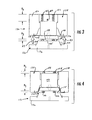
- Fig. 1 schematically illustrates a tool (e.g., mold assembly 130) that can be used in the manufacture of or forming of a container or construct 300 ( Fig. 6 ), in accordance with one embodiment.
- the container 300 can have an injection-molded structure 305 with similar characteristics as the container and injection-molded structure described in co-assigned U.S. Patent Application No. 11/715,718 filed March 8, 2007 ("the '718 application"). Further, the container and injection-molded structure may be formed by similar methods, tools, apparatus, etc. as disclosed in the '718 application.
- the mold assembly 130 of the present disclosure may be used to form containers that do not have injection molded features without departing from the disclosure.
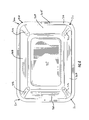
- the container 300 has a bottom wall 307, and four side walls 309 extending upwardly from the bottom wall.
- the injection-molded structure 305 can include a flange 310 that extends around the perimeter of the container and fingers 312 that extend downward from the flange 310 at respective corners 311 of the container.
- the container 300 and injection-molded structure 305 can be otherwise shaped, arranged, configured, and/or omitted without departing from the disclosure.
- the mold assembly 130 is in an open configuration in Fig. 1 , and it includes a male mold 132 (e.g., core) and a female mold 134 (e.g., cavity).
- the female mold 134 includes a space 133 that is defined by a sidewall 135 that is generally shaped to correspond with the shape of the construct 300.
- the male mold 132 is shaped to generally correspond to the shape of the space 133 to form the three-dimensionally-shaped construct 300 from a generally flat blank 22 that is pressed into the space.
- the male mold 132 and/or the female mold 134 may be otherwise shaped and/or arranged without departing from the disclosure.
- core 132 includes an outer mold or core base 136 to which a nose unit 138 (e.g., core plate or nose) is mounted.
- the nose 138 is moveably mounted to the core base 136 and is connected to the core base by a group of core springs 140, two of which are shown in Fig. 1 .
- a single core spring 140 could be provided.
- four securing elements, such as securing pins 144, protrude from the core base 136 for aiding in the forming of the container.
- securing elements e.g., securing pins 144
- a port 146 (e.g., with a valve gate) is optionally defined in the core base 136, or otherwise provided, for injecting fluid injection-molding material (e.g., resin) or the like, into the mold assembly 130 to form the injection-molded structure 305 of the construct 300.
- the port 146 is in the form of, or includes, a valve gate. The port 146 can be omitted such that the tool 130 forms the construct that is free from an injection-molded structure without departing from the disclosure.
- the cavity 134 includes a cavity base 150 to which an embossing unit 152 (e.g., cavity plate or articulating portion) is movably mounted.
- an embossing unit 152 e.g., cavity plate or articulating portion
- a group of cavity springs 154 urge the articulating portion 152 toward the core 132.
- a single cavity spring 154 can be provided or the springs can be omitted without departing from the disclosure.
- a group of locating pins 156 can be mounted to the cavity base 150 in an arrangement that is for helping to position the blank 22 in a predetermined location.
- the cavity 134 includes a flange surface 164 that is generally perpendicular to the sidewall 135 and further at least partially defines the space 133.
- the core springs 140 in the male mold 132 and the cavity springs 154 in the female mold 134 are of different strength to prevent pinching the sidewalls 309 of the blank 22 when forming the construct.
- the cavity springs 154 in the female mold 134 are stronger than the core springs 140 of the male mold 132 so that the cavity springs have a higher resistance to compression. The higher strength of the cavity springs 154 allows the core springs 140 to compress when the nose 138 presses the blank 22 against the articulating portion 152, prior to movement of the articulating portion 152 and corresponding compression of the cavity springs 154.
- the core springs 140 have a first end 143 in contact with a surface 145 of the core base 136.
- the core springs 140 have a second end 147 in contact with a surface 149 of the nose 138.
- the cavity springs 154 have a first end 155 in contact with a surface 157 of the cavity base 150.
- the cavity springs 154 have a second end 159 in contact with a surface 161 of the articulating portion 152.
- the core springs 140 and/or the cavity springs 154 could be otherwise shaped, arranged, and/or configured without departing from the disclosure.
- the core springs 140 can have a diameter of at least approximately 0.75 inches (19 mm), and an overall, non-compressed length of at least approximately 1.25 inches (30 mm).
- the cavity springs 154 can have a diameter of at least approximately 0.75 inches (20 mm), and an overall, non-compressed length of at least approximately 7.0 inches (175 mm).
- the core springs 140 and the cavity springs 154 can be a medium heavy duty die spring of the type commercially available from Associated Spring Raymond of Maumee, OH.
- the core springs 140 and/or the cavity springs 154 could be otherwise shaped, arranged, and/or configured to be other types and/or sizes of springs. All dimensional information presented herein is intended to be exemplary and is not intended to limit the scope of the disclosure.
- the cavity springs 154 have a first strength, or resistance to linear compression
- the core springs 140 have a second strength, or resistance to linear compression.
- the cavity springs 154 provide a resistance to the movement of the articulating portion 152 relative to the cavity base 150.
- the core springs 140 provide a resistance to the movement of the nose 138 relative to the core base 136.
- the first strength of the cavity springs 154 is greater than the second strength of the cores springs 140 so that when the core 132 and cavity 134 are brought together, in contact with the blank 22 located therebetween, the core springs are compressed prior to the compression of the cavity springs.
- the surface 145 of the base 136 is moved closer to the surface 149 of the nose 138 when the base 136 is moved in the direction of arrow A1 ( Fig. 1 ) relative to the nose.
- the moving of the surface 145 occurs prior to the movement of the articulating portion 152 moving in the direction of arrow A2 ( Fig. 1 ) resulting in the compression of the cavity springs 155.
- the resistance to movement of the articulating portion 152 could be maintained to be greater than the resistance to movement of the nose 138 by mechanisms other than the cavity springs 154.
- the cavity springs 154 and/or the core springs 140 could be mechanisms other than coil springs (e.g., gas springs, reciprocating pistons, or other mechanism that provides resistance to linear compression).
- the core 136 has an external surface 171 for cooperating with the surface 135 of the cavity 134 to form the sidewalls 309 of the container 300.
- the external surface 171 of the core 136 includes a first portion 171a on the base 136 and a second portion 171b on the nose 138.
- the first portion 171 a and the second portion 171b are spaced apart by a gap 175.
- the nose 138 is in an extended position such that the gap 175 has a maximum dimension H1.
- the articulating portion 152 of the cavity 134 is shown in an extended position wherein the articulating portion is spaced apart from the surface 157 of the cavity base 150 by a gap 179 having a maximum dimension H2.
- the gap 175 is first reduced by the movement of the nose 138 in the direction of arrow A1 and then the gap 179 is reduced by the movement of the articulating portion 152 in the direction of arrow A2.
- FIG. 1 A method of forming the construct 300 ( Fig. 6 ) from the forming tool 130 will now be described.
- the blank 22 is first placed between the cavity 134 and the core 132 as generally shown schematically in Fig. 1 .
- the core 132 is moved in the direction of arrows A3 so that the nose 138 contacts the blank 22 that is held between the core and the cavity 134 and presses the blank against the articulating portion 152.
- the cavity 134 could be moved in a direction opposite to the arrows A3 so that the articulating portion 152 presses the blank 22 against the nose 138.
- the core 132 is further moved in the direction of arrows A3 so that the gap 175 between the nose 138 and the base 136 is reduced to a minimum dimension H3.
- the gap 175 is reduced when the core springs 140 are compressed by the upward movement of the base 136 relative to the nose 138.
- the articulating portion 152 of the cavity 134 does not move because the force applied to the core 136 to move it toward the cavity is insufficient to overcome the resistance to compression of the cavity springs 154. As shown in Fig.
- the articulating section 152 moves in the direction of arrow A2 to reduce the height of the gap 179 to a minimum distance of H5.
- the cavity springs 154 could be partially compressed (e.g., so that the height of the gap 179 has a dimension less than H3 and greater than H2).
- the blank 22 is formed into the container 200 by the configuration of the forming tool 130 shown in Fig. 4 with the external surface 171 of the core 132 pressing the portions of the blank corresponding with the sidewalls 309 of the container against the surface 135 of the cavity 134.
- the core springs 140 are compressed prior to fully receiving the core 132 into the cavity 134 to complete the formation or shaping of the blank 22 into the construct 300.
- the compression of the core springs 140 minimizes the height of the gap 179 prior to completion of the forming or shaping of the blank 22 into the shape of the construct 300.
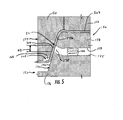
- the injection-molded structure 305 can be formed by injecting injection-molding material (e.g., polymeric material, resin, etc.) through the port 146 that fills an injection cavity 205 ( Fig. 5 ) formed between the flange surface 164 of the cavity 134 and the blank 22.
- injection cavity 205 is shaped to form the injection-molded structure 305 that can include the flange 310 and fingers 312 but the injection cavity can be otherwise shaped, arranged, configured, and/or omitted without departing from the disclosure.
- the injection molding occurs after completion of the formation or shaping of the blank 22 by fully receiving the core 132 into the cavity 134 so that the blank is pressed against the external surface 171 of the core and the surface 135 of the cavity.
- the blanks can be formed from paperboard, corrugated cardboard or other materials having properties suitable for at least generally enabling respective functionalities described above.
- Paperboard is typically of a caliper such that it is heavier and more rigid than ordinary paper
- corrugated cardboard is typically of a caliper such that it is heavier and more rigid than paperboard.
- at least the side of the paperboard or cardboard that will be an exterior surface in the carton erected therefrom will be coated with a clay coating, or the like.
- the clay coating can be printed over with product, advertising, price-coding, and other information or images.
- the blanks may then be coated with a varnish to protect any information printed on the blanks.
- the blanks may also be coated with, for example, a moisture barrier layer, on one or both sides.
- the blanks can also be laminated to or coated with one or more sheet-like materials.
Landscapes
- Engineering & Computer Science (AREA)
- Mechanical Engineering (AREA)
- Manufacturing & Machinery (AREA)
- Moulds For Moulding Plastics Or The Like (AREA)
- Containers Having Bodies Formed In One Piece (AREA)
- Injection Moulding Of Plastics Or The Like (AREA)
- Details Of Rigid Or Semi-Rigid Containers (AREA)
Claims (20)
- Werkzeug (130) zum Formen eines Gebildes (300) aus einem Rohling (22), wobei das Werkzeug umfasst:eine Kavität (134), die einsatzfähig ist, um einen Rohling aufzunehmen, wobei die Kavität einen gelenkigen Abschnitt (152) und eine Kavitätsbasis (150) umfasst, wobei die Kavität (134) mindestens eine Seitenwand (135) zum Formen mindestens einer Seitenwand (309) des Gebildes (300) umfasst, wobei das Gebilde ein dreidimensionaler Behälter ist, der aus dem Rohling (22) geformt wird, wobei der gelenkige Abschnitt beweglich mit der Kavitätsbasis verbunden ist, wobei die Kavität mindestens eine Kavitätsfeder (154) zum Steuern der Bewegung des gelenkigen Abschnitts relativ zu der Kavitätsbasis umfasst;einen Kern (132), der mit der Kavität wirkverbunden ist, wobei der Kern einsatzfähig ist, um in die Kavität eingeführt zu werden, um den Rohling mindestens teilweise zu einem Gebilde zu formen, wobei der Kern eine Kernbasis (136) und eine Nase (138), die beweglich mit der Kernbasis verbunden ist, umfasst, wobei der Kern (132) eine Oberfläche (171) zum Zusammenwirken mit der mindestens einen Seitenwand (135) aufweist, um den Rohling (22) mindestens teilweise zu dem Gebilde (300) zu formen, wobei die Oberfläche einen Abschnitt einer äußeren Oberfläche (171a) der Kernbasis (136) und einen Abschnitt einer äußeren Oberfläche (171b) der Nase (138) umfasst, wobei die äußere Oberfläche der Kernbasis und die äußere Oberfläche der Nase voneinander beabstandet sind, um mindestens teilsweise einen Zwischenraum (175) zu bilden, wobei der Kern mindestens eine Kernfeder (140) zum Steuern von Bewegung der Nase relativ zu der Kernbasis umfasst, dadurch gekennzeichnet, dassdie mindestens eine Kavitätsfeder eine erste Stärke aufweist und die mindestens eine Kernfeder eine zweite Stärke aufweist, wobei die erste Stärke größer als die zweite Stärke ist.
- Werkzeug (130) nach Anspruch 1, wobei die Kavitätsfeder (154) ein erstes Ende (155), das mit einer Oberfläche (157) der Kavitätsbasis (150) in Kontakt steht, und ein zweites Ende (159), das mit einer Oberfläche (161) des gelenkigen Abschnitts (152) in Kontakt steht, aufweist, wobei die Kernfeder (140) ein erstes Ende (143), das mit einer Oberfläche (145) der Kernbasis (136) in Kontakt steht, und ein zweites Ende (147), das mit einer Oberfläche (149) der Nase (138) in Kontakt steht, aufweist.
- Werkzeug (130) nach Anspruch 1, wobei das Werkzeug eine Spritzkavität (205) umfasst, die mindestens teilweise aus der Kavität (134) und dem Kern (132) gebildet ist, wobei die Spritzkavität zum Aufnehmen von flüssigem Harz um mindestens einen Abschnitt des Umfangs des Rohlings (22) dient.
- Werkzeug (130) nach Anspruch 3, wobei die Spritzkavität (205) zum Formen eines spritzgegossenen Bandes an einem Flansch des Gebildes bestimmt ist.
- Werkzeug (130) nach Anspruch 4, wobei die Spritzkavität (205) zum Formen eines spritzgegossenen Streifens bestimmt ist, der sich von dem spritzgegossenen Band erstreckt und mindestens teilweise eine Ecke (311) des Gebildes (300) definiert.
- Werkzeug (130) nach Anspruch 2, wobei die mindestens eine Kavitätsfeder (154) eine erste Länge zwischen jeweiligen Enden (155, 159) der Kavitätsfeder aufweist und die mindestens eine Kernfeder (140) eine zweite Länge zwischen jeweiligen Enden (143, 147) der Kernfeder aufweist, wobei die erste Länge größer als die zweite Länge ist.
- Werkzeug (130) nach Anspruch 6, wobei die erste Länge mindestens etwa 175 Millimeter und die zweite Länge mindestens etwa 30 Millimeter beträgt.
- Werkzeug (130) nach Anspruch 7, wobei die mindestens eine Kavitätsfeder (154) einen ersten Durchmesser und die mindestens eine Kernfeder (140) einen zweiten Durchmesser aufweist, wobei der erste Durchmesser und der zweite Durchmesser im Wesentlichen gleich sind.
- Werkzeug (130) nach Anspruch 1, wobei der Zwischenraum (175) vor dem Formen des Rohlings (22) zu dem Gebilde (300) durch einen ersten Abstand (H1) zwischen der Kernbasis (136) und der Nase (138) definiert ist und der Zwischenraum nachdem der Kern gegen den Rohling gedrückt wurde, um die mindestens eine Kernfeder (140) zusammenzudrücken, durch einen zweiten Abstand (H3) zwischen der Kernbasis und der Nase definiert ist.
- Werkzeug (130) nach Anspruch 9, wobei, während der Kern (132) weiter in die Kavität (134) bewegt wird, um den Rohling (22) zu dem Gebilde (300) zu formen, der Zwischenraum (175) in dem zweiten Abstand (H3) gehalten wird.
- Verfahren zum Formen eines Gebildes (300) aus einem Rohling (22), wobei das Verfahren umfasst:Bereitstellen eines Rohlings;Anordnen des Rohlings in einem Formwerkzeug (130), wobei das Formwerkzeug umfasst: eine Kavität (134) mit einem gelenkigen Abschnitt (152), einer Kavitätsbasis (150) und mindestens einer Kavitätsfeder (154) zum Steuern der Bewegung des gelenkigen Abschnitts relativ zu der Kavitätsbasis und einen Kern (132), der eine Kernbasis (136), eine Nase (138) und mindestens eine Kernfeder (140) zum Steuern der Bewegung der Nase relativ zu der Kernbasis umfasst;Schließen des Werkzeugs, während sich der Rohling in dem Werkzeug befindet,wobei das Schließen des Werkzeugs das Pressen des Kerns gegen den Rohling umfasst, um die mindestens eine Kernfeder zusammenzudrücken, und ferner das Bewegen des Kerns, um zu bewirken, dass sich der gelenkige Abschnitt relativ zu der Kavitätsbasis bewegt, wobei die mindestens eine Kernfeder vor dem Aufnehmen des Kerns in die Kavität, um das Formen des Rohlings zu dem Gebilde abzuschließen, zusammengedrückt wird;wobei der Kern (132) eine Oberfläche (171) aufweist, die einen Abschnitt einer äußeren Oberfläche (171a) der Kernbasis (136) und einen Abschnitt einer äußeren Oberfläche (171b) der Nase (138) umfasst, wobei die äußere Oberfläche der Kernbasis und die äußere Oberfläche der Nase voneinander beabstandet sind, um mindestens teilweise einen Zwischenraum (175) zu definieren, wobei der Zwischenraum zwischen der äußeren Oberfläche der Nase und der äußeren Oberfläche der Kernbasis durch das Zusammendrücken der mindestens einen Kernfeder (140) und die Bewegung der Nase relativ zu der Kernbasis verkleinert wird.
- Verfahren nach Anspruch 11, wobei die mindestens eine Kernfeder (140) vor der Bewegung des gelenkigen Abschnitts (152) relativ zu der Kavitätsbasis (150) zusammengedrückt wird.
- Verfahren nach Anspruch 11, wobei das Schließen des Werkzeugs (130) das Pressen des Rohlings (22) gegen eine Oberfläche (135) der Kavität (134) umfasst, um das Gebilde (300) mindestens teilweise zu formen.
- Verfahren nach Anspruch 13, wobei das Pressen des Rohlings (22) gegen die Oberfläche (135) der Kavität (134) das Fertigstellen des Formens des Rohlings zu dem Gebilde (300) umfasst, wobei das Fertigstellen des Formens des Rohlings zu dem Gebilde das vollständige Zusammendrücken der mindestens einen Kavitätsfeder (154) umfasst.
- Verfahren nach Anspruch 11, wobei das Werkzeug (130) ferner eine Spritzkavität (205) umfasst, die mindestens teilweise aus der Kavität (134) und dem Kern (132) gebildet ist, wobei das Verfahren ferner das Formen eines Flansches des Gebildes und das Spritzgießen eines Merkmals auf den Flansch umfasst.
- Verfahren nach Anspruch 11, wobei der Zwischenraum (175) verkleinert wird, ehe der Kern (132) in der Kavität (134) aufgenommen wird.
- Verfahren nach Anspruch 11, wobei die Oberfläche (171) des Kerns (132) den Rohling (22) gegen eine Oberfläche (135) der Kavität (134) presst, um den Rohling mindestens teilweise zu dem Gebilde (300) zu formen.
- Verfahren nach Anspruch 11, wobei die Bewegung des Kerns (132) das mindestens teilweise Formen des Rohlings (22) zu dem Gebilde (300) umfasst, wobei die Bewegung des Kerns bewirkt, dass sich der gelenkige Abschnitt (152) der Kavität (134) relativ zu der Kavitätsbasis (150) bewegt.
- Verfahren nach Anspruch 18, wobei die mindestens eine Kavitätsfeder (154) zusammengedrückt wird, nachdem die mindestens eine Kernfeder (140) zusammengedrückt wird.
- Verfahren nach Anspruch 11, wobei die Kavitätsfeder (154) eine erste Stärke und die Kernfeder (140) eine zweite Stärke aufweist, wobei die erste Stärke größer als die zweite Stärke ist.
Applications Claiming Priority (2)
| Application Number | Priority Date | Filing Date | Title |
|---|---|---|---|
| US1785007P | 2007-12-31 | 2007-12-31 | |
| PCT/US2008/088605 WO2009088904A2 (en) | 2007-12-31 | 2008-12-31 | Tool for forming construct |
Publications (3)
| Publication Number | Publication Date |
|---|---|
| EP2231376A2 EP2231376A2 (de) | 2010-09-29 |
| EP2231376A4 EP2231376A4 (de) | 2013-10-09 |
| EP2231376B1 true EP2231376B1 (de) | 2015-08-05 |
Family
ID=40853684
Family Applications (1)
| Application Number | Title | Priority Date | Filing Date |
|---|---|---|---|
| EP08870276.6A Not-in-force EP2231376B1 (de) | 2007-12-31 | 2008-12-31 | Werkzeug und verfahren zum formen von konstrukten |
Country Status (5)
| Country | Link |
|---|---|
| US (1) | US20100314801A1 (de) |
| EP (1) | EP2231376B1 (de) |
| JP (1) | JP5197758B2 (de) |
| CA (1) | CA2707083C (de) |
| WO (1) | WO2009088904A2 (de) |
Cited By (1)
| Publication number | Priority date | Publication date | Assignee | Title |
|---|---|---|---|---|
| EP4570474A1 (de) * | 2023-12-11 | 2025-06-18 | G. Mondini SpA | Verfahren und vorrichtung zur herstellung eines behälters |
Families Citing this family (29)
| Publication number | Priority date | Publication date | Assignee | Title |
|---|---|---|---|---|
| ES2396314T3 (es) | 2002-03-15 | 2013-02-20 | Graphic Packaging International, Inc. | Procedimiento y herramienta para conformar un recipiente que tiene una característica de moldeado por inyección |
| US8124201B2 (en) | 2006-03-10 | 2012-02-28 | Graphic Packaging International, Inc. | Injection-molded composite construct |
| WO2008049048A2 (en) | 2006-10-18 | 2008-04-24 | Graphic Packaging International, Inc. | Tool for forming a three dimensional article or container |
| JP5220867B2 (ja) | 2007-12-28 | 2013-06-26 | グラフィック パッケージング インターナショナル インコーポレイテッド | 射出成形複合構造体及び該構造体を成形するための工具 |
| US7975871B2 (en) | 2008-04-04 | 2011-07-12 | Graphic Packaging International, Inc. | Container with injection-molded feature and tool for forming container |
| FI122995B (fi) * | 2008-08-12 | 2012-09-28 | Stora Enso Oyj | Muottijärjestelmä ja menetelmä astian valmistamiseksi |
| FI122782B (fi) * | 2008-08-12 | 2012-06-29 | Stora Enso Oyj | Muottijärjestelmä ja menetelmä kartonkipohjaisen astian valmistamiseksi |
| EP2442924A4 (de) | 2009-06-17 | 2017-03-01 | Graphic Packaging International, Inc. | Werkzeug zum bilden eines dreidimensionalen behälters oder konstrukts |
| EP2477900B1 (de) | 2009-09-14 | 2015-08-12 | Graphic Packaging International, Inc. | Rohling und formwerkzeug zum formen eines behälters |
| DE102009059197A1 (de) * | 2009-12-17 | 2011-06-22 | ThyssenKrupp Steel Europe AG, 47166 | Verfahren und Vorrichtung zur Herstellung eines Halbschalenteils |
| EP2519404A2 (de) | 2009-12-30 | 2012-11-07 | Graphic Packaging International, Inc. | Vorrichtung und verfahren zum positionieren und betreiben auf einem konstrukt |
| CN102825713B (zh) * | 2011-06-17 | 2016-02-10 | 上海永红汽车零部件有限公司 | 发泡模具的滤芯脱模机构 |
| US10464280B2 (en) | 2011-08-30 | 2019-11-05 | Shanghai Yanfeng Jinqiao Automotive Trim Systems Co. Ltd. | Trim component for vehicle interior |
| MX391384B (es) | 2011-08-30 | 2025-03-21 | Johnson Controls Tech Co | Sistema y método para fabricar un componente de guarnición para vehículo mediante moldeo por conformación e inyección por compresión concurrente. |
| BR112014003503B1 (pt) * | 2011-09-09 | 2020-06-23 | Graphic Packaging International, Llc | Ferramenta para a formação de um recipiente a partir de uma blanqueta, e método de formar um recipiente a partir de uma blanqueta |
| WO2013148237A1 (en) | 2012-03-30 | 2013-10-03 | Graphic Packaging International, Inc. | Composite package |
| US10093268B2 (en) | 2012-08-27 | 2018-10-09 | Shanghai Yanfeng Jinqiao Automotive Trim Systems Co. Ltd. | Trim component for vehicle interior |
| ES2647635T3 (es) | 2012-10-17 | 2017-12-22 | Graphic Packaging International, Inc. | Recipiente con líneas de incisiones |
| ITMO20130293A1 (it) * | 2013-10-16 | 2015-04-17 | Cms Spa | Apparato di formatura |
| CN104227981B (zh) * | 2014-09-16 | 2016-08-24 | 金成彪 | 防滑垫成型模具 |
| EP3261942B1 (de) | 2015-02-27 | 2019-12-18 | Graphic Packaging International, LLC | Behälter mit beschichtung |
| WO2017117495A1 (en) | 2015-12-30 | 2017-07-06 | Graphic Packaging International, Inc. | Susceptor on a fiber reinforced film for extended functionality |
| WO2020006290A1 (en) | 2018-06-28 | 2020-01-02 | Shanghai Yanfeng Jinqiao Automotive Trim Systems Co. Ltd. | Vehicle trim component |
| DE102020201081A1 (de) | 2020-01-29 | 2021-07-29 | Volkswagen Aktiengesellschaft | Vorrichtung und Verfahren zur Herstellung einer dreidimensional geformten Kanalwand |
| DE102020127015A1 (de) | 2020-10-14 | 2022-04-14 | Valeo Schalter Und Sensoren Gmbh | Eingabevorrichtung für ein Kraftfahrzeug, Verfahren und Werkzeug zum Herstellen eines Kunststoffteils für eine Eingabevorrichtung eines Kraftfahrzeugs |
| US11938699B2 (en) | 2021-07-07 | 2024-03-26 | Brown Llc | Methods and systems for producing pressware |
| US12269234B2 (en) * | 2021-07-07 | 2025-04-08 | Brown Llc | Methods and systems for producing pressware |
| CN114801320B (zh) * | 2022-05-16 | 2023-05-26 | 山东大学 | 一种纸板冲压成形装置及方法 |
| DE102022129118A1 (de) * | 2022-11-03 | 2024-05-08 | Syntegon Technology Gmbh | Vorrichtung und Verfahren zum Umformen eines Verpackungselements |
Family Cites Families (95)
| Publication number | Priority date | Publication date | Assignee | Title |
|---|---|---|---|---|
| US2328563A (en) * | 1939-03-15 | 1943-09-07 | Stickless Corp | Tray |
| US2607080A (en) * | 1947-03-15 | 1952-08-19 | John H F Stewart | Mold for producing plastic articles without flash |
| US2522397A (en) * | 1947-06-18 | 1950-09-12 | Helen A Palmer | Baking utensil |
| US2634880A (en) * | 1951-05-23 | 1953-04-14 | William H Gravatt | Disposable liner for garbage cans |
| US3040949A (en) * | 1959-12-09 | 1962-06-26 | Diamond National Corp | Food container |
| US3099377A (en) * | 1960-08-17 | 1963-07-30 | American Can Co | Dish or the like |
| US3190530A (en) * | 1961-05-10 | 1965-06-22 | Illinois Tool Works | Thin wall container with thickened rim structure |
| US3144167A (en) * | 1961-07-19 | 1964-08-11 | American Can Co | Foamed plastic containier |
| US3135455A (en) * | 1962-04-16 | 1964-06-02 | Johnson & Johnson | Composite sterilizable container |
| US3286876A (en) * | 1964-06-15 | 1966-11-22 | Goodyear Aerospace Corp | Containers |
| US3342915A (en) * | 1965-02-03 | 1967-09-19 | Illinois Tool Works | Undercut molding apparatus and method |
| US3511902A (en) * | 1966-12-06 | 1970-05-12 | Johnson & Johnson | Method of molding composite containers |
| CH514475A (fr) * | 1969-07-09 | 1971-10-31 | Intercan S A C O Fiduciaire Wa | Installation de fabrication de récipients comportant au moins en partie des parois composites |
| US3680733A (en) * | 1970-07-20 | 1972-08-01 | Samuel J Winslow | Hollowware construction |
| US3684633A (en) * | 1971-01-05 | 1972-08-15 | Mobil Oil Corp | Laminated thermoplastic foam-film dish |
| US3834606A (en) * | 1972-04-06 | 1974-09-10 | Torsten Jeppsson Ab | Packaging trays and methods of making them |
| US3785544A (en) * | 1972-05-15 | 1974-01-15 | Phillips Petroleum Co | Tray with strengthening member |
| US4149838A (en) * | 1973-06-12 | 1979-04-17 | Airfix Industries Limited | Production of composite elements |
| GB1463314A (en) * | 1973-06-22 | 1977-02-02 | Airfix Ind Ltd | Containers |
| CH565647A5 (de) * | 1973-07-02 | 1975-08-29 | Valyi Emery I | |
| GB1470977A (en) * | 1973-08-07 | 1977-04-21 | Ici Ltd | Container |
| GB1504526A (en) * | 1974-05-28 | 1978-03-22 | Airfix Ind Ltd | Containers |
| US4001471A (en) * | 1974-06-26 | 1977-01-04 | Airfix Industries Limited | Thermoplastic seam between juxtaposed edges of blank material |
| US4183435A (en) * | 1978-08-24 | 1980-01-15 | Champion International Corporation | Polymeric multiple-layer sheet material |
| US4404162A (en) * | 1979-07-16 | 1983-09-13 | Sumitomo Bakelite Company Ltd. | Process for producing a thin-wall deep drawn container of thermoplastic resin |
| FR2480708A1 (fr) * | 1980-11-07 | 1981-10-23 | Impression Cartonnage Ste Pari | Contenant en carton plie revetu d'une pellicule en matiere synthetique et muni d'un cadre peripherique en une seule piece ainsi que son procede de fabrication |
| US4609140C1 (en) * | 1982-04-13 | 2002-04-16 | James River Corp | Rigid paperboard container and method and apparatus for producing same |
| US4533312A (en) * | 1982-12-27 | 1985-08-06 | Holdt J W Von | Simplified collapsible mold core |
| EP0128425B1 (de) * | 1983-06-03 | 1990-11-07 | FP Corporation | Behälter |
| US4721499C1 (en) * | 1984-03-20 | 2002-06-04 | Fort James Corp | Method of producing a rigid paperboard container |
| AU572632B2 (en) * | 1984-03-20 | 1988-05-12 | James River Corporation Of Virginia | Rigid paperboard container |
| US4624380A (en) * | 1985-12-05 | 1986-11-25 | Wernette H George | Disposable litter enclosure |
| US4865921A (en) * | 1987-03-10 | 1989-09-12 | James Riker Corporation Of Virginia | Microwave interactive laminate |
| USRE34683E (en) * | 1987-03-10 | 1994-08-02 | James River Corporation Of Virginia | Control of microwave interactive heating by patterned deactivation |
| US4775771A (en) * | 1987-07-30 | 1988-10-04 | James River Corporation | Sleeve for crisping and browning of foods in a microwave oven and package and method utilizing same |
| US4935089A (en) * | 1987-10-30 | 1990-06-19 | W. R. Grace & Co.-Conn. | Method of making a thermoformable barrier sheet |
| CA1292934C (en) * | 1988-05-20 | 1991-12-10 | Donald G. Beckett | Microwave heating material |
| US5410135A (en) * | 1988-09-01 | 1995-04-25 | James River Paper Company, Inc. | Self limiting microwave heaters |
| US4890439A (en) * | 1988-11-09 | 1990-01-02 | James River Corporation | Flexible disposable material for forming a food container for microwave cooking |
| GB8827759D0 (en) * | 1988-11-28 | 1988-12-29 | Beckett D E | Selective microwave heating material-ii |
| US5519195A (en) * | 1989-02-09 | 1996-05-21 | Beckett Technologies Corp. | Methods and devices used in the microwave heating of foods and other materials |
| FR2644389B1 (fr) | 1989-03-16 | 1991-07-05 | Solvay | Procede pour assembler par moulage un support rigide deformable et un revetement decoratif souple et moule pour sa realisation |
| US4971201A (en) * | 1989-03-30 | 1990-11-20 | Sathre Robert C | Stacking rim for soft-sided containers |
| CA2009207A1 (en) * | 1990-02-02 | 1991-08-02 | D. Gregory Beckett | Controlled heating of foodstuffs by microwave energy |
| US5190209A (en) * | 1990-05-18 | 1993-03-02 | Sonoco Products Company | Plastic chime overlay for fibre drum |
| US5183706A (en) * | 1990-08-03 | 1993-02-02 | W. R. Grace & Co.-Conn. | Forming web for lining a rigid container |
| US5628921A (en) * | 1991-02-14 | 1997-05-13 | Beckett Technologies Corp. | Demetallizing procedure |
| CA2041062C (en) * | 1991-02-14 | 2000-11-28 | D. Gregory Beckett | Demetallizing procedure |
| US5266386A (en) * | 1991-02-14 | 1993-11-30 | Beckett Industries Inc. | Demetallizing procedure |
| US5213902A (en) * | 1991-02-19 | 1993-05-25 | Beckett Industries Inc. | Microwave oven package |
| US5221419A (en) * | 1991-02-19 | 1993-06-22 | Beckett Industries Inc. | Method for forming laminate for microwave oven package |
| US5260537A (en) * | 1991-06-17 | 1993-11-09 | Beckett Industries Inc. | Microwave heating structure |
| US5506036A (en) * | 1991-09-04 | 1996-04-09 | Ab Tetra Pak | Easy-to-recycle laminated material for packaging use |
| US5335847A (en) * | 1992-01-21 | 1994-08-09 | Elopak Systems A.G. | Flat top container and blank for constructing same |
| GB9201932D0 (en) * | 1992-01-29 | 1992-03-18 | Beckett Ind Inc | Novel microwave heating structure |
| US5219461A (en) * | 1992-04-28 | 1993-06-15 | Baker Hughes Incorporated | Reinforced elastomer lining for pump casing and associated method of manufacture |
| US5523042A (en) * | 1993-02-10 | 1996-06-04 | Solo Cup Company | Method of making plastic plate with rolled edge rim |
| US5424517A (en) * | 1993-10-27 | 1995-06-13 | James River Paper Company, Inc. | Microwave impedance matching film for microwave cooking |
| US5565228A (en) * | 1995-05-02 | 1996-10-15 | Gics & Vermee, L.P. | Ovenable food product tray and an ovenable food product package |
| US5800724A (en) * | 1996-02-14 | 1998-09-01 | Fort James Corporation | Patterned metal foil laminate and method for making same |
| US5759422A (en) * | 1996-02-14 | 1998-06-02 | Fort James Corporation | Patterned metal foil laminate and method for making same |
| AU4006497A (en) * | 1996-08-26 | 1998-03-19 | Fort James Corporation | Microwavable container |
| AU4006197A (en) * | 1996-08-26 | 1998-03-19 | Fort James Corporation | Microwavable package |
| CA2250434C (en) * | 1997-01-29 | 2002-11-26 | Fort James Corporation | Microwave oven heating element having broken loops |
| US6149006A (en) * | 1997-08-19 | 2000-11-21 | General Mills, Inc. | Refrigerated food product container |
| KR19990023720U (ko) * | 1997-12-08 | 1999-07-05 | 김영환 | 사출금형의 언더컷 성형장치 |
| US6414290B1 (en) * | 1998-03-19 | 2002-07-02 | Graphic Packaging Corporation | Patterned microwave susceptor |
| US5934472A (en) * | 1998-04-06 | 1999-08-10 | Tekni-Plex, Inc. | Processor tray |
| US6308831B1 (en) * | 1999-07-12 | 2001-10-30 | J. E. Saxe & Co. | Container and kit for protection and display of collectible items |
| US6204492B1 (en) * | 1999-09-20 | 2001-03-20 | Graphic Packaging Corporation | Abuse-tolerant metallic packaging materials for microwave cooking |
| US6433322B2 (en) * | 1999-09-20 | 2002-08-13 | Graphic Packaging Corporation | Abuse-tolerant metallic packaging materials for microwave cooking |
| KR100360299B1 (ko) * | 1999-12-21 | 2002-11-13 | 윤선영 | 합성수지 성형물 및 성형방법, 그리고 그 성형장치 |
| US6682676B1 (en) * | 2000-03-15 | 2004-01-27 | Patent Holding Company | Method for molding a thermoplastic sandwich material |
| US6682675B1 (en) * | 2000-03-15 | 2004-01-27 | Patent Holding Company | Method for co-molding a thermoplastic material with a thermoplastic sandwich material |
| US6547127B2 (en) * | 2000-09-08 | 2003-04-15 | Bradford Company | Tote box with multiple piece top rail including corner pieces with projections |
| US6988654B2 (en) * | 2001-01-18 | 2006-01-24 | Graphic Packaging International, Inc. | Container with improved stacking/denesting capability |
| WO2002083256A2 (en) * | 2001-04-17 | 2002-10-24 | Light Wave, Ltd. | Contoured variably tensionable soft membrane ride surface for ride attraction |
| US6823624B2 (en) * | 2001-07-17 | 2004-11-30 | S.I.T., Inc. | Plastic article with protuberance |
| US6717121B2 (en) * | 2001-09-28 | 2004-04-06 | Graphic Packaging International, Inc. | Patterned microwave susceptor element and microwave container incorporating same |
| US6677563B2 (en) * | 2001-12-14 | 2004-01-13 | Graphic Packaging Corporation | Abuse-tolerant metallic pattern arrays for microwave packaging materials |
| WO2003066435A2 (en) * | 2002-02-08 | 2003-08-14 | Graphic Packaging International, Inc. | Insulating microwave interactive packaging |
| US7323669B2 (en) * | 2002-02-08 | 2008-01-29 | Graphic Packaging International, Inc. | Microwave interactive flexible packaging |
| ES2396314T3 (es) * | 2002-03-15 | 2013-02-20 | Graphic Packaging International, Inc. | Procedimiento y herramienta para conformar un recipiente que tiene una característica de moldeado por inyección |
| JP4369770B2 (ja) * | 2003-06-16 | 2009-11-25 | 株式会社秀英 | 紙製容器 |
| CA2544321C (en) * | 2003-11-11 | 2009-10-06 | Graphic Packaging International, Inc. | Nestable container with uniform stacking features |
| JP4327205B2 (ja) * | 2004-02-09 | 2009-09-09 | グラフィック パッケージング インターナショナル インコーポレイテッド | 電子レンジ調理用パッケージ |
| US7000825B2 (en) * | 2004-02-25 | 2006-02-21 | Rogar Capital Corporation | Food enclosing container with rebondable rim and liquid absorption and barrier layers |
| DE602006020282D1 (de) * | 2005-05-25 | 2011-04-07 | Graphic Packaging Int Inc | Mikrowellenverpackung für aus mehreren komponenten bestehende mahlzeiten |
| KR100707268B1 (ko) * | 2005-10-08 | 2007-04-16 | 삼성전자주식회사 | 영상보간장치 및 영상보간방법 |
| JP2007111888A (ja) * | 2005-10-18 | 2007-05-10 | Toyo Seikan Kaisha Ltd | カップ状容器の成形装置および成形方法並びにカップ状容器 |
| US8124201B2 (en) * | 2006-03-10 | 2012-02-28 | Graphic Packaging International, Inc. | Injection-molded composite construct |
| US8680448B2 (en) * | 2006-05-15 | 2014-03-25 | Graphic Packaging International, Inc. | Microwavable construct with contoured heating surface |
| US8803050B2 (en) * | 2006-05-15 | 2014-08-12 | Graphic Packaging International, Inc. | Microwavable construct with contoured heating surface |
| WO2008049048A2 (en) * | 2006-10-18 | 2008-04-24 | Graphic Packaging International, Inc. | Tool for forming a three dimensional article or container |
| US7975871B2 (en) * | 2008-04-04 | 2011-07-12 | Graphic Packaging International, Inc. | Container with injection-molded feature and tool for forming container |
-
2008
- 2008-12-31 EP EP08870276.6A patent/EP2231376B1/de not_active Not-in-force
- 2008-12-31 WO PCT/US2008/088605 patent/WO2009088904A2/en not_active Ceased
- 2008-12-31 JP JP2010540948A patent/JP5197758B2/ja not_active Expired - Fee Related
- 2008-12-31 CA CA2707083A patent/CA2707083C/en not_active Expired - Fee Related
-
2010
- 2010-06-24 US US12/822,573 patent/US20100314801A1/en not_active Abandoned
Cited By (2)
| Publication number | Priority date | Publication date | Assignee | Title |
|---|---|---|---|---|
| EP4570474A1 (de) * | 2023-12-11 | 2025-06-18 | G. Mondini SpA | Verfahren und vorrichtung zur herstellung eines behälters |
| EP4570475A1 (de) * | 2023-12-11 | 2025-06-18 | G. Mondini SpA | Verfahren und vorrichtung zur herstellung eines aussenskeletts eines behälters |
Also Published As
| Publication number | Publication date |
|---|---|
| EP2231376A2 (de) | 2010-09-29 |
| US20100314801A1 (en) | 2010-12-16 |
| WO2009088904A3 (en) | 2009-09-24 |
| JP2011507741A (ja) | 2011-03-10 |
| CA2707083A1 (en) | 2009-07-16 |
| EP2231376A4 (de) | 2013-10-09 |
| WO2009088904A2 (en) | 2009-07-16 |
| JP5197758B2 (ja) | 2013-05-15 |
| CA2707083C (en) | 2012-10-09 |
Similar Documents
| Publication | Publication Date | Title |
|---|---|---|
| CA2707083C (en) | Tool for forming construct | |
| JP5905103B2 (ja) | 3次元物品又は容器を形成する工具 | |
| CA2719697C (en) | Container with injection-molded feature and tool for forming container | |
| JP3631033B2 (ja) | 薄板材からなるケース | |
| CN112867600B (zh) | 纸质的包装用缓冲托盘的制造方法及由此制造的缓冲托盘 | |
| RU2497678C2 (ru) | Формовочная система для изготовления контейнера на основе картона | |
| TW200932394A (en) | Apparatus and method for manufacturing square necked-in cans | |
| JP6137056B2 (ja) | 自動車用樹脂部品の製造方法及び自動車用樹脂部品の製造装置 | |
| EP2017183B1 (de) | Verpackungspuffermaterial | |
| CN103042722B (zh) | 纸盒内折边裱糊成型机构 | |
| CN101637792B (zh) | 汽车防撞杆吸能盒引导槽冲压成型装置 | |
| CN101918190B (zh) | 在基于纸板的容器内形成分隔体的模具系统 | |
| CN221292478U (zh) | 一种纸盒折叠卷边成型模具 | |
| CN111571940B (zh) | 一种模具以及用于该模具的工具 | |
| CN221562392U (zh) | 成型模具及成型装置 | |
| CN223085577U (zh) | 一种用于包装箱生产的支撑卡折叠成型装置 | |
| CN204712524U (zh) | 一种瓦楞纸箱压痕装置 | |
| CN219407117U (zh) | 一种纸托成型机构 | |
| JP2004122410A (ja) | 紙シート成形体 | |
| JP3136760U6 (ja) | 梱包用緩衝材 | |
| CN120936486A (zh) | 用于形成具有带有胶合拐角的顶部凸缘的容器的方法和机器 |
Legal Events
| Date | Code | Title | Description |
|---|---|---|---|
| PUAI | Public reference made under article 153(3) epc to a published international application that has entered the european phase |
Free format text: ORIGINAL CODE: 0009012 |
|
| 17P | Request for examination filed |
Effective date: 20100617 |
|
| AK | Designated contracting states |
Kind code of ref document: A2 Designated state(s): AT BE BG CH CY CZ DE DK EE ES FI FR GB GR HR HU IE IS IT LI LT LU LV MC MT NL NO PL PT RO SE SI SK TR |
|
| AX | Request for extension of the european patent |
Extension state: AL BA MK RS |
|
| DAX | Request for extension of the european patent (deleted) | ||
| A4 | Supplementary search report drawn up and despatched |
Effective date: 20130905 |
|
| RIC1 | Information provided on ipc code assigned before grant |
Ipc: B29C 43/02 20060101AFI20130830BHEP Ipc: B29C 43/32 20060101ALI20130830BHEP Ipc: B29C 43/36 20060101ALI20130830BHEP Ipc: B21D 22/18 20060101ALI20130830BHEP Ipc: B21D 11/10 20060101ALI20130830BHEP |
|
| 17Q | First examination report despatched |
Effective date: 20140624 |
|
| GRAP | Despatch of communication of intention to grant a patent |
Free format text: ORIGINAL CODE: EPIDOSNIGR1 |
|
| INTG | Intention to grant announced |
Effective date: 20150316 |
|
| GRAS | Grant fee paid |
Free format text: ORIGINAL CODE: EPIDOSNIGR3 |
|
| GRAA | (expected) grant |
Free format text: ORIGINAL CODE: 0009210 |
|
| AK | Designated contracting states |
Kind code of ref document: B1 Designated state(s): AT BE BG CH CY CZ DE DK EE ES FI FR GB GR HR HU IE IS IT LI LT LU LV MC MT NL NO PL PT RO SE SI SK TR |
|
| REG | Reference to a national code |
Ref country code: GB Ref legal event code: FG4D |
|
| REG | Reference to a national code |
Ref country code: CH Ref legal event code: EP |
|
| REG | Reference to a national code |
Ref country code: AT Ref legal event code: REF Ref document number: 740449 Country of ref document: AT Kind code of ref document: T Effective date: 20150815 |
|
| REG | Reference to a national code |
Ref country code: IE Ref legal event code: FG4D |
|
| REG | Reference to a national code |
Ref country code: DE Ref legal event code: R096 Ref document number: 602008039429 Country of ref document: DE |
|
| REG | Reference to a national code |
Ref country code: AT Ref legal event code: MK05 Ref document number: 740449 Country of ref document: AT Kind code of ref document: T Effective date: 20150805 |
|
| REG | Reference to a national code |
Ref country code: FR Ref legal event code: PLFP Year of fee payment: 8 |
|
| REG | Reference to a national code |
Ref country code: LT Ref legal event code: MG4D |
|
| REG | Reference to a national code |
Ref country code: NL Ref legal event code: MP Effective date: 20150805 |
|
| PG25 | Lapsed in a contracting state [announced via postgrant information from national office to epo] |
Ref country code: FI Free format text: LAPSE BECAUSE OF FAILURE TO SUBMIT A TRANSLATION OF THE DESCRIPTION OR TO PAY THE FEE WITHIN THE PRESCRIBED TIME-LIMIT Effective date: 20150805 Ref country code: LV Free format text: LAPSE BECAUSE OF FAILURE TO SUBMIT A TRANSLATION OF THE DESCRIPTION OR TO PAY THE FEE WITHIN THE PRESCRIBED TIME-LIMIT Effective date: 20150805 Ref country code: LT Free format text: LAPSE BECAUSE OF FAILURE TO SUBMIT A TRANSLATION OF THE DESCRIPTION OR TO PAY THE FEE WITHIN THE PRESCRIBED TIME-LIMIT Effective date: 20150805 Ref country code: GR Free format text: LAPSE BECAUSE OF FAILURE TO SUBMIT A TRANSLATION OF THE DESCRIPTION OR TO PAY THE FEE WITHIN THE PRESCRIBED TIME-LIMIT Effective date: 20151106 Ref country code: NO Free format text: LAPSE BECAUSE OF FAILURE TO SUBMIT A TRANSLATION OF THE DESCRIPTION OR TO PAY THE FEE WITHIN THE PRESCRIBED TIME-LIMIT Effective date: 20151105 |
|
| PG25 | Lapsed in a contracting state [announced via postgrant information from national office to epo] |
Ref country code: AT Free format text: LAPSE BECAUSE OF FAILURE TO SUBMIT A TRANSLATION OF THE DESCRIPTION OR TO PAY THE FEE WITHIN THE PRESCRIBED TIME-LIMIT Effective date: 20150805 Ref country code: PL Free format text: LAPSE BECAUSE OF FAILURE TO SUBMIT A TRANSLATION OF THE DESCRIPTION OR TO PAY THE FEE WITHIN THE PRESCRIBED TIME-LIMIT Effective date: 20150805 Ref country code: HR Free format text: LAPSE BECAUSE OF FAILURE TO SUBMIT A TRANSLATION OF THE DESCRIPTION OR TO PAY THE FEE WITHIN THE PRESCRIBED TIME-LIMIT Effective date: 20150805 Ref country code: SE Free format text: LAPSE BECAUSE OF FAILURE TO SUBMIT A TRANSLATION OF THE DESCRIPTION OR TO PAY THE FEE WITHIN THE PRESCRIBED TIME-LIMIT Effective date: 20150805 Ref country code: PT Free format text: LAPSE BECAUSE OF FAILURE TO SUBMIT A TRANSLATION OF THE DESCRIPTION OR TO PAY THE FEE WITHIN THE PRESCRIBED TIME-LIMIT Effective date: 20151207 Ref country code: IS Free format text: LAPSE BECAUSE OF FAILURE TO SUBMIT A TRANSLATION OF THE DESCRIPTION OR TO PAY THE FEE WITHIN THE PRESCRIBED TIME-LIMIT Effective date: 20151205 Ref country code: ES Free format text: LAPSE BECAUSE OF FAILURE TO SUBMIT A TRANSLATION OF THE DESCRIPTION OR TO PAY THE FEE WITHIN THE PRESCRIBED TIME-LIMIT Effective date: 20150805 |
|
| PG25 | Lapsed in a contracting state [announced via postgrant information from national office to epo] |
Ref country code: NL Free format text: LAPSE BECAUSE OF FAILURE TO SUBMIT A TRANSLATION OF THE DESCRIPTION OR TO PAY THE FEE WITHIN THE PRESCRIBED TIME-LIMIT Effective date: 20150805 |
|
| PG25 | Lapsed in a contracting state [announced via postgrant information from national office to epo] |
Ref country code: EE Free format text: LAPSE BECAUSE OF FAILURE TO SUBMIT A TRANSLATION OF THE DESCRIPTION OR TO PAY THE FEE WITHIN THE PRESCRIBED TIME-LIMIT Effective date: 20150805 Ref country code: SK Free format text: LAPSE BECAUSE OF FAILURE TO SUBMIT A TRANSLATION OF THE DESCRIPTION OR TO PAY THE FEE WITHIN THE PRESCRIBED TIME-LIMIT Effective date: 20150805 Ref country code: CZ Free format text: LAPSE BECAUSE OF FAILURE TO SUBMIT A TRANSLATION OF THE DESCRIPTION OR TO PAY THE FEE WITHIN THE PRESCRIBED TIME-LIMIT Effective date: 20150805 Ref country code: IT Free format text: LAPSE BECAUSE OF FAILURE TO SUBMIT A TRANSLATION OF THE DESCRIPTION OR TO PAY THE FEE WITHIN THE PRESCRIBED TIME-LIMIT Effective date: 20150805 Ref country code: DK Free format text: LAPSE BECAUSE OF FAILURE TO SUBMIT A TRANSLATION OF THE DESCRIPTION OR TO PAY THE FEE WITHIN THE PRESCRIBED TIME-LIMIT Effective date: 20150805 |
|
| REG | Reference to a national code |
Ref country code: DE Ref legal event code: R097 Ref document number: 602008039429 Country of ref document: DE |
|
| PG25 | Lapsed in a contracting state [announced via postgrant information from national office to epo] |
Ref country code: BE Free format text: LAPSE BECAUSE OF NON-PAYMENT OF DUE FEES Effective date: 20151231 Ref country code: RO Free format text: LAPSE BECAUSE OF FAILURE TO SUBMIT A TRANSLATION OF THE DESCRIPTION OR TO PAY THE FEE WITHIN THE PRESCRIBED TIME-LIMIT Effective date: 20150805 |
|
| PLBE | No opposition filed within time limit |
Free format text: ORIGINAL CODE: 0009261 |
|
| STAA | Information on the status of an ep patent application or granted ep patent |
Free format text: STATUS: NO OPPOSITION FILED WITHIN TIME LIMIT |
|
| 26N | No opposition filed |
Effective date: 20160509 |
|
| PG25 | Lapsed in a contracting state [announced via postgrant information from national office to epo] |
Ref country code: LU Free format text: LAPSE BECAUSE OF FAILURE TO SUBMIT A TRANSLATION OF THE DESCRIPTION OR TO PAY THE FEE WITHIN THE PRESCRIBED TIME-LIMIT Effective date: 20151231 Ref country code: MC Free format text: LAPSE BECAUSE OF FAILURE TO SUBMIT A TRANSLATION OF THE DESCRIPTION OR TO PAY THE FEE WITHIN THE PRESCRIBED TIME-LIMIT Effective date: 20150805 |
|
| REG | Reference to a national code |
Ref country code: CH Ref legal event code: PL |
|
| PG25 | Lapsed in a contracting state [announced via postgrant information from national office to epo] |
Ref country code: SI Free format text: LAPSE BECAUSE OF FAILURE TO SUBMIT A TRANSLATION OF THE DESCRIPTION OR TO PAY THE FEE WITHIN THE PRESCRIBED TIME-LIMIT Effective date: 20150805 |
|
| REG | Reference to a national code |
Ref country code: IE Ref legal event code: MM4A |
|
| PG25 | Lapsed in a contracting state [announced via postgrant information from national office to epo] |
Ref country code: LI Free format text: LAPSE BECAUSE OF NON-PAYMENT OF DUE FEES Effective date: 20151231 Ref country code: CH Free format text: LAPSE BECAUSE OF NON-PAYMENT OF DUE FEES Effective date: 20151231 Ref country code: IE Free format text: LAPSE BECAUSE OF NON-PAYMENT OF DUE FEES Effective date: 20151231 |
|
| REG | Reference to a national code |
Ref country code: FR Ref legal event code: PLFP Year of fee payment: 9 |
|
| PG25 | Lapsed in a contracting state [announced via postgrant information from national office to epo] |
Ref country code: BE Free format text: LAPSE BECAUSE OF FAILURE TO SUBMIT A TRANSLATION OF THE DESCRIPTION OR TO PAY THE FEE WITHIN THE PRESCRIBED TIME-LIMIT Effective date: 20150805 |
|
| PG25 | Lapsed in a contracting state [announced via postgrant information from national office to epo] |
Ref country code: HU Free format text: LAPSE BECAUSE OF FAILURE TO SUBMIT A TRANSLATION OF THE DESCRIPTION OR TO PAY THE FEE WITHIN THE PRESCRIBED TIME-LIMIT; INVALID AB INITIO Effective date: 20081231 Ref country code: BG Free format text: LAPSE BECAUSE OF FAILURE TO SUBMIT A TRANSLATION OF THE DESCRIPTION OR TO PAY THE FEE WITHIN THE PRESCRIBED TIME-LIMIT Effective date: 20150805 |
|
| PG25 | Lapsed in a contracting state [announced via postgrant information from national office to epo] |
Ref country code: CY Free format text: LAPSE BECAUSE OF FAILURE TO SUBMIT A TRANSLATION OF THE DESCRIPTION OR TO PAY THE FEE WITHIN THE PRESCRIBED TIME-LIMIT Effective date: 20150805 |
|
| PG25 | Lapsed in a contracting state [announced via postgrant information from national office to epo] |
Ref country code: TR Free format text: LAPSE BECAUSE OF FAILURE TO SUBMIT A TRANSLATION OF THE DESCRIPTION OR TO PAY THE FEE WITHIN THE PRESCRIBED TIME-LIMIT Effective date: 20150805 Ref country code: MT Free format text: LAPSE BECAUSE OF FAILURE TO SUBMIT A TRANSLATION OF THE DESCRIPTION OR TO PAY THE FEE WITHIN THE PRESCRIBED TIME-LIMIT Effective date: 20150805 |
|
| REG | Reference to a national code |
Ref country code: FR Ref legal event code: PLFP Year of fee payment: 10 |
|
| REG | Reference to a national code |
Ref country code: DE Ref legal event code: R082 Ref document number: 602008039429 Country of ref document: DE Representative=s name: GRAETTINGER MOEHRING VON POSCHINGER PATENTANWA, DE Ref country code: DE Ref legal event code: R081 Ref document number: 602008039429 Country of ref document: DE Owner name: GRAPHIC PACKAGING INTERNATIONAL, LLC, ATLANTA, US Free format text: FORMER OWNER: GRAPHIC PACKAGING INTERNATIONAL, INC., MARIETTA, GA., US |
|
| PGFP | Annual fee paid to national office [announced via postgrant information from national office to epo] |
Ref country code: FR Payment date: 20191226 Year of fee payment: 12 |
|
| PGFP | Annual fee paid to national office [announced via postgrant information from national office to epo] |
Ref country code: GB Payment date: 20191227 Year of fee payment: 12 Ref country code: DE Payment date: 20191231 Year of fee payment: 12 |
|
| REG | Reference to a national code |
Ref country code: DE Ref legal event code: R119 Ref document number: 602008039429 Country of ref document: DE |
|
| GBPC | Gb: european patent ceased through non-payment of renewal fee |
Effective date: 20201231 |
|
| PG25 | Lapsed in a contracting state [announced via postgrant information from national office to epo] |
Ref country code: FR Free format text: LAPSE BECAUSE OF NON-PAYMENT OF DUE FEES Effective date: 20201231 |
|
| PG25 | Lapsed in a contracting state [announced via postgrant information from national office to epo] |
Ref country code: DE Free format text: LAPSE BECAUSE OF NON-PAYMENT OF DUE FEES Effective date: 20210701 Ref country code: GB Free format text: LAPSE BECAUSE OF NON-PAYMENT OF DUE FEES Effective date: 20201231 |