EP2232032B1 - Klappe zur blockierung eines flüssigkeitskanals für ein auto - Google Patents
Klappe zur blockierung eines flüssigkeitskanals für ein auto Download PDFInfo
- Publication number
- EP2232032B1 EP2232032B1 EP08872552.8A EP08872552A EP2232032B1 EP 2232032 B1 EP2232032 B1 EP 2232032B1 EP 08872552 A EP08872552 A EP 08872552A EP 2232032 B1 EP2232032 B1 EP 2232032B1
- Authority
- EP
- European Patent Office
- Prior art keywords
- flap
- cap
- drive shaft
- shaft
- duct
- Prior art date
- Legal status (The legal status is an assumption and is not a legal conclusion. Google has not performed a legal analysis and makes no representation as to the accuracy of the status listed.)
- Active
Links
Images


Classifications
-
- F—MECHANICAL ENGINEERING; LIGHTING; HEATING; WEAPONS; BLASTING
- F02—COMBUSTION ENGINES; HOT-GAS OR COMBUSTION-PRODUCT ENGINE PLANTS
- F02D—CONTROLLING COMBUSTION ENGINES
- F02D9/00—Controlling engines by throttling air or fuel-and-air induction conduits or exhaust conduits
- F02D9/08—Throttle valves specially adapted therefor; Arrangements of such valves in conduits
- F02D9/10—Throttle valves specially adapted therefor; Arrangements of such valves in conduits having pivotally-mounted flaps
- F02D9/1005—Details of the flap
-
- F—MECHANICAL ENGINEERING; LIGHTING; HEATING; WEAPONS; BLASTING
- F16—ENGINEERING ELEMENTS AND UNITS; GENERAL MEASURES FOR PRODUCING AND MAINTAINING EFFECTIVE FUNCTIONING OF MACHINES OR INSTALLATIONS; THERMAL INSULATION IN GENERAL
- F16K—VALVES; TAPS; COCKS; ACTUATING-FLOATS; DEVICES FOR VENTING OR AERATING
- F16K1/00—Lift valves or globe valves, i.e. cut-off apparatus with closure members having at least a component of their opening and closing motion perpendicular to the closing faces
- F16K1/16—Lift valves or globe valves, i.e. cut-off apparatus with closure members having at least a component of their opening and closing motion perpendicular to the closing faces with pivoted closure-members
- F16K1/18—Lift valves or globe valves, i.e. cut-off apparatus with closure members having at least a component of their opening and closing motion perpendicular to the closing faces with pivoted closure-members with pivoted discs or flaps
- F16K1/22—Lift valves or globe valves, i.e. cut-off apparatus with closure members having at least a component of their opening and closing motion perpendicular to the closing faces with pivoted closure-members with pivoted discs or flaps with axis of rotation crossing the valve member, e.g. butterfly valves
Definitions
- the invention relates to the field of gas dosers, and more particularly the plastic dosers used in motor vehicles.
- an air-metering unit controls the amount of air admitted to an internal combustion engine.
- a metering device disposed in an air duct, comprises a shutter fixedly secured to a rotary drive shaft mounted in said air duct.
- the drive shaft is conventionally guided in rotation by two guide bearings mounted in openings formed in the air duct for the passage of the shaft.
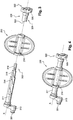
- the flap 200 integral with the shaft 300, pivots by an angle ⁇ to control the opening of the air duct.
- the air flows in the pipe 100 when the flap is in the P 0 position and is locked in the P 1 position.
- these metal shutters first need to be positioned, either in a housing or a slot, and then to be fixed.
- Such a mounting method is suitable only for metal shutters that can be drilled or tighten strongly.
- a first alternative consists in molding, in a single piece, the flap and the drive shaft.
- This immediate solution known for example by the patent US 6,986,860 B2 , does not allow to mount the monobloc shutter in a standard tubular air pipe. Indeed, it is necessary to use a two-part pipe arranged to fit around the one-piece flap. Such a monobloc flap is not suitable and requires significant structural changes of the doser and its environment.
- a second alternative is to provide a bore 210 in the shutter 200, the drive shaft 300 through successively a first opening 403 formed in the pipe 100, the bore 210 of the flap 200 and a second opening 403 formed in the pipe 100.
- Two guide bearings 401, 402 are respectively mounted in the openings 403 to guide the shaft 300 which is rotated by a motor not shown. Subsequently, the term drive end 301, the end of the shaft 300 connected to the motor and by free end its opposite end.
- the bore In order not to clutter the gas line 100, the bore must have a small diameter diameter while the shaft must have a diameter large enough to be rotated accurately. It is then necessary to reduce the diameter of the shaft 300 at its free end 302 so that it can be inserted into the bore 210, the drive ends 301 and free 302 of the shaft 300 then having not the same diameter.
- guide bearings 401, 402 In order to maintain a substantially symmetrical proportioner on both sides of the flap 200, guide bearings 401, 402, having different cradle diameters, are used to guide each of the ends of the shaft 300 as shown in FIG. figure 2 . However, the use of two different bearings 401, 402 generates uneven guidance on both sides of the flap, one of the bearings being worn faster than the other.
- the object of the invention is to solve some of these disadvantages and to provide a symmetrical doser using identical standard bearings without requiring significant modifications of the air metering device or its environment.
- Such a drive shaft covered with a cap allows simple assembly and distributed wear of the bearings
- the end portion of the drive shaft of the drive shaft comprises a connecting flattened to fit into a locking housing in the cap.
- the connecting flat makes it possible to connect the shaft and the cap by interlocking while allowing the transmission of the rotational movement.
- two identical sealing means are mounted respectively on the drive shaft and the cap.
- the bore formed in the shutter is of oblong section.
- An oblong section advantageously provides a keying during the insertion of the shaft into the bore of the flap.
- the locking housing comprises at least one longitudinal groove for exhausting the air during the insertion of the drive shaft into the cap.
- the invention also relates to a single fluid pipe metering device comprising an assembly of a shutter for closing a fluid pipe and a drive shaft of said shutter.
- the invention also relates to a dual fluid line metering device comprising two sets of a closing flap of a fluid line and a drive shaft of said flap.
- the dispenser single or double, is plastic which advantageously allows to reduce its mass.
- Such a mounting method advantageously allows the flap to be easily disposed in the pipe, the cap participating in centering said flap.
- a shutter 200 of a gas pipe is driven by a drive shaft 300, itself driven by a motor, not shown, at its drive end 301.
- the shaft 300 shown in more detail on the figure 3 , is covered at its free end 302, opposite that of the drive 301, by a cap 320 integral in rotation with the shaft 300.
- the term "drive end” designates the end directly receiving the driving torque and, by free end, its opposite end.
- the drive shaft 300 comprises a drive end 301 and a free end 302, the cap 320 comprising, for its part, a drive end 321 and a free end 322.
- the drive shaft 300 extends along an axis X. Its drive end 301 comprises a motor arm 313, extending perpendicularly to the axis X and arranged to transmit the rotational movement of the motor to the drive shaft 300.
- the drive shaft 300 When considering the drive shaft 300 in the X direction, from its drive end 301 to its free end 302, it has four successive concentric portions 311, 314, 315 and 316 whose section is decreasing.
- the larger diameter portion 311, said drive portion 311, is of substantially circular section to allow precise guidance by means of a guide bearing.
- the second portion 314, designated central portion 314, is of oblong section whose maximum overall diameter corresponds to the diameter of the drive portion 311.
- the portions 315, 316 of smaller diameter, form the end portion 312 of the drive shaft 300.
- the portion 316 whose diameter is the smallest, comprises a flat face forming a connecting flat with the cap 320.
- the drive end 321 of the cap 320 includes a locking housing 323 for receiving the free end 302 of the drive shaft 300.
- the locking housing 323 is longitudinal and extends into the housing. the cap 320 along the X axis as shown on the figure 6 .
- the locking housing 323 here comprises two longitudinal grooves 324 allowing the air, resting in the housing 323, to escape during the insertion of the drive shaft 300 into the cap 320, the connecting flat of the drive shaft 300 fitting into the locking housing 323 of the cap 320 to secure them in rotation.
- the cap 320 is of oblong section, its diameter being equal to that of the drive portion 311 of the drive shaft 300. Thus, when the shaft 300 and the cap 320 are nested together, they form a shaft said The cap 320 is terminated at its free end 322 by a substantially square portion 325.
- guide bearings 501 of the drive shaft 300 are respectively mounted in openings formed in the pipe 100 for the passage of the shaft 300. These bearings 501 are mounted on both sides of the flap 200, as shown in FIG. the figure 5 , on the drive portion 311 of the shaft 300 and on the cap 320 respectively.
- the bearings 501 are in the form of ball bearings whose cradle diameter is identical.
- Means 502 sealing the openings of the pipe are here mounted with the guide bearings 501 on the drive shaft 300 and on the cap 320, avoiding a risk of leakage of gas from the pipe into the openings.
- Ways 502 sealing are here in the form of elastomer rings. It goes without saying that other means might also be appropriate.
- the shutter shutter 200 is in the form of a circular plastic disc on which is mounted a circumferential seal 201 for sealing between the circumference of the flap 200 and the gas line.
- the flap 200 may also have an oblong shape, the section of the pipe then being adapted.
- an oblong section makes it easier to insert the shutter 200 into the pipe by complementarity of shapes.
- a bore 210 is formed diametrically in the flap 200 and extends along the axis X.
- the section of the bore 210 is here oblong and substantially equal to that of the central portion 314 of the shaft 300.
- the drive shaft 300 can be inserted without difficulty by its free end 302 into the bore 210 of the flap 200 by complementary shapes, the central portion 314 of the shaft 300 being in contact with the bore 210 after insertion.
- a section of oblong shape is particularly advantageous because it allows a better transmission of the engine torque of the drive shaft 300 shutter flap 200.
- Reinforcing ribs 202 are formed, perpendicular to the bore 210, on each of the faces of the flap 200 to increase the rigidity.
- the flap 200 is rotated in the gas line by the drive shaft 300 mounted in the two openings of the pipe.
- the shutter 200 is inserted into the gas line through one of the gas inlet or outlet sections so that the bore 210 of the shutter 200 is oriented in the X direction perpendicular to the axis of the pipe. , and aligned with the two openings formed diametrically in the pipe for the passage of the shaft 300.
- the two guide bearings 501 are then mounted with the two elastomer rings 502 respectively in the two openings of the gas pipe.
- the cap 320 is inserted into a first opening of the pipe by threading the driving end 321 of the cap 320 successively into the first guide bearing 501 and into the first elastomer ring 502, the square portion 325 of the cap 320. protruding outside the pipe.
- the cap 320 is before the shutter shutter 200 so that the cap 320 facilitates the alignment and centering of the bore 210 in the X direction.
- the drive shaft 300 is introduced into the second opening of the pipe by introducing its free end 302 successively into the guide bearing 501, the elastomer ring 502, the bore 210 and finally into the cap 320, the flat part of the drive shaft 300 fitting into the locking housing 323 of the cap 320.
- the connecting flat in the locking housing 323 the air resting in the housing 323 is driven via the two longitudinal grooves 324 formed in the housing 323. The connection between the shaft 300 and the cap 320 is then sealed.
- the shaft 300 and the cap 320 are integral in rotation and have an equal diameter outside the pipe.
- the shutter assembly of the gas pipe, formed by the shutter 200 and the drive shaft 300, is then symmetrical with respect to a plane orthogonal to the X axis as shown in FIG. figure 5 .
- Guiding bearings 501 and 502 identical sealing means are used on both sides of the shutter 200, allowing, on the one hand, homogeneous guidance and distributed wear bearings 501, and, secondly, a standardization of bearings and sealing means allowing economies of scale and storage facilities.
- single or dual feeders can be manufactured to precisely regulate the flow of fluid in a conduit.
Landscapes
- Engineering & Computer Science (AREA)
- General Engineering & Computer Science (AREA)
- Mechanical Engineering (AREA)
- Chemical & Material Sciences (AREA)
- Combustion & Propulsion (AREA)
- Lift Valve (AREA)
- Pipe Accessories (AREA)
Claims (9)
- Einheit aus einer Verschlussklappe (200) einer Fluidleitung und einer Antriebswelle (300) der Klappe (200), die sich in einer in der Verschlussklappe (200) gebildeten Bohrung (210) erstreckt,- wobei die Antriebswelle (300) auf einer Seite der Klappe (200) durch einen Antriebsabschnitt (311) der Welle (300) in Drehung versetzt wird, der in einem ersten Drehlager (501) drehend montiert ist,- wobei die Antriebswelle (300) sich vom Antriebsabschnitt (301) bis zu einem Endabschnitt (302) erstreckt,wobei die Einheit dadurch gekennzeichnet ist, dass der Endabschnitt (302) mit einer Kappe (320) bedeckt ist, die mit der Welle (300) auf der anderen Seite der Klappe (200) drehfest verbunden ist, wobei die Kappe (320) in einem zweiten Lager (501) gleichen Halterungsdurchmessers wie das erste drehend montiert ist, wobei die Verbindung zwischen der Welle (300) und der Kappe (320) dicht ist.
- Einheit nach Anspruch 1, wobei der Endabschnitt (302) der Antriebswelle (300) eine Verbindungsabflachung enthält, die eingerichtet ist, um sich in eine in der Kappe (320) ausgesparte Blockieraufnahme (323) einzufügen.
- Einheit nach einem der Ansprüche 1 bis 2, wobei zwei gleiche Dichtungseinrichtungen (502) auf die Antriebswelle (300) bzw. die Kappe (320) montiert sind.
- Einheit nach einem der Ansprüche 1 bis 3, wobei die in der Verschlussklappe (200) gebildete Bohrung (210) einen länglichen Querschnitt hat.
- Einheit nach einem der Ansprüche 1 bis 4, wobei die Blockieraufnahme (323) mindestens eine Längsrille (324) für den Austritt der Luft beim Einführen der Antriebswelle (300) in die Kappe (320) enthält.
- Einfacher Fluidleitungsdosierer, der eine Einheit nach einem der vorhergehenden Ansprüche enthält.
- Doppelter Fluidleitungsdosierer, der zwei Einheiten nach einem der Ansprüche 1 bis 5 enthält.
- Einfacher oder doppelter Dosierer nach einem der Ansprüche 6 oder 7, dadurch gekennzeichnet, dass der Dosierer aus Kunststoff ist.
- Verfahren zur Montage einer Verschlussklappe (200) in eine Fluidleitung, in der Öffnungen für den Durchgang einer Antriebswelle (300) der Verschlussklappe (200) ausgebildet sind, Verfahren, bei dem:- die Klappe (200) durch einen Fluiddurchgangsquerschnitt der Leitung in die Leitung eingeführt wird;- eine Kappe (320) in eine erste Öffnung der Leitung auf einer Seite der Klappe eingeführt wird;- die Antriebswelle (300) nacheinander eingeführt wird:i. in eine zweite Öffnung der Leitung auf der anderen Seite der Klappe;ii. in eine in der Verschlussklappe (200) ausgebildete Bohrung (210); undiii. in eine in der Kappe (320) ausgebildete Blockieraufnahme (323), wobei die Kappe (320) dann mit der Antriebswelle (300) drehfest verbunden ist, wobei die Verbindung zwischen der Welle (300) und der Kappe (320) dicht ist.
Applications Claiming Priority (2)
| Application Number | Priority Date | Filing Date | Title |
|---|---|---|---|
| FR0708943A FR2925644B1 (fr) | 2007-12-20 | 2007-12-20 | Volet d'obturation de conduite de fluide pour vehicule automobile |
| PCT/FR2008/001765 WO2009103893A2 (fr) | 2007-12-20 | 2008-12-17 | Volet d'obturation de conduite de fluide pour véhicule automobile |
Publications (2)
| Publication Number | Publication Date |
|---|---|
| EP2232032A2 EP2232032A2 (de) | 2010-09-29 |
| EP2232032B1 true EP2232032B1 (de) | 2017-01-11 |
Family
ID=39580431
Family Applications (1)
| Application Number | Title | Priority Date | Filing Date |
|---|---|---|---|
| EP08872552.8A Active EP2232032B1 (de) | 2007-12-20 | 2008-12-17 | Klappe zur blockierung eines flüssigkeitskanals für ein auto |
Country Status (3)
| Country | Link |
|---|---|
| EP (1) | EP2232032B1 (de) |
| FR (1) | FR2925644B1 (de) |
| WO (1) | WO2009103893A2 (de) |
Families Citing this family (3)
| Publication number | Priority date | Publication date | Assignee | Title |
|---|---|---|---|---|
| DE102011106744B3 (de) * | 2011-06-28 | 2012-12-27 | Pierburg Gmbh | Ventilvorrichtung zur Regelung eines Abgasstroms einer Verbrennungskraftmaschine |
| CN102979647B (zh) * | 2012-12-14 | 2014-12-10 | 青岛华涛汽车模具有限公司 | 一种进气歧管可变系统及可变进气歧管 |
| DE102014119086A1 (de) * | 2014-12-18 | 2016-06-23 | Knorr-Bremse Systeme für Nutzfahrzeuge GmbH | Ventilklappenanordnung einer Ventilvorrichtung, und eine entsprechende Ventilvorrichtung |
Family Cites Families (3)
| Publication number | Priority date | Publication date | Assignee | Title |
|---|---|---|---|---|
| DE102004050791A1 (de) * | 2004-10-19 | 2006-04-20 | Robert Bosch Gmbh | Drosselvorrichtung |
| US7213568B2 (en) * | 2005-04-15 | 2007-05-08 | Arctic Cat Inc. | Throttle body and plate |
| US7117846B1 (en) * | 2005-11-22 | 2006-10-10 | Keihin Corporation | Throttle control apparatus |
-
2007
- 2007-12-20 FR FR0708943A patent/FR2925644B1/fr active Active
-
2008
- 2008-12-17 EP EP08872552.8A patent/EP2232032B1/de active Active
- 2008-12-17 WO PCT/FR2008/001765 patent/WO2009103893A2/fr not_active Ceased
Non-Patent Citations (1)
| Title |
|---|
| None * |
Also Published As
| Publication number | Publication date |
|---|---|
| WO2009103893A2 (fr) | 2009-08-27 |
| EP2232032A2 (de) | 2010-09-29 |
| FR2925644B1 (fr) | 2012-08-31 |
| WO2009103893A3 (fr) | 2009-10-22 |
| FR2925644A1 (fr) | 2009-06-26 |
Similar Documents
| Publication | Publication Date | Title |
|---|---|---|
| EP2751437B1 (de) | Vorrichtung zum verbinden einer lenksäule mit einem lenkgetriebegehäuse | |
| EP3298243B1 (de) | Turbinenmotoreinheit zum schmieren einer lagerhalterung | |
| EP2322779B1 (de) | Herstellungsverfahren eines Ansaugkrümmers, und entsprechender Ansaugkrümmer | |
| EP1872043B1 (de) | Röhrenförmige verbindung mit variablem winkel | |
| EP2850298B1 (de) | Ventil zum steuerung eines flüssigkeitsstroms mit einer drehverschlussvorrichtung | |
| CA1271180A (fr) | Robinet a papillon a caractere universel et procede de fabrication dudit robinet | |
| EP0019496B1 (de) | Drosselklappe und Verfahren zu ihrer Herstellung | |
| EP2232032B1 (de) | Klappe zur blockierung eines flüssigkeitskanals für ein auto | |
| EP3649000A1 (de) | Verschlussklappe für eine vorrichtung zur regelung eines luftstroms für ein vorbaumodul eines kraftfahrzeugs | |
| FR2905731A1 (fr) | Structure de fixation de roulements | |
| EP0715113A1 (de) | Entleer- oder Ablassvorrichtung für eine Leitung | |
| FR2748539A1 (fr) | Appareil d'accouplement hydrocinetique a piece d'entrainement de languettes, notamment pour vehicule automobile | |
| EP0057123B1 (de) | Kupplungsmittel für den Rotor einer Einzelschneckenpumpe | |
| EP3126720B1 (de) | Ventil mit verbessertem ventilkörper und herstellungsverfahren eines solchen ventils | |
| EP1891305A2 (de) | Vorrichtung zum verbinden einer vakuumpumpe mit einer nockenwelle einschliesslich der mittel zur zufuhr von schmierflüssigkeit | |
| FR2956148A1 (fr) | Actionneur a bras pour vantail | |
| FR3001270A3 (fr) | "differentiel de transmission comportant des moyens de friction perfectionnes" | |
| FR2689581A1 (fr) | Chapeau de métal auto-bloquant et palier en plastique. | |
| FR2928986A1 (fr) | Joint imperdable pour raccord banjo et ensemble comportant un raccord banjo et un tel joint | |
| EP3683150B1 (de) | Verbindungsvorrichtung, die zwischen mindestens zwei teilen schwenkbar ist, luftfahrzeug, das eine abdeckung umfasst, die mit dieser schwenkbaren verbindungsvorrichtung ausgestattet ist | |
| EP1092880A1 (de) | Schraubmechanismusbefestigungsvorrichtung mit Spielausgleichsvorrichtung zwischen zwei Bauteilen | |
| EP1605195B1 (de) | Rohrkupplungssystem und dazu gehöriges Montageverfahren | |
| FR3139420A1 (fr) | Actionneur, notamment de type électromécanique | |
| WO2024200974A1 (fr) | Assemblage d'un distributeur hydraulique sans corps de vanne avec son actionneur | |
| FR3019255A1 (fr) | Vanne a fixation facilitee d'un ressort de torsion |
Legal Events
| Date | Code | Title | Description |
|---|---|---|---|
| PUAI | Public reference made under article 153(3) epc to a published international application that has entered the european phase |
Free format text: ORIGINAL CODE: 0009012 |
|
| 17P | Request for examination filed |
Effective date: 20100625 |
|
| AK | Designated contracting states |
Kind code of ref document: A2 Designated state(s): AT BE BG CH CY CZ DE DK EE ES FI FR GB GR HR HU IE IS IT LI LT LU LV MC MT NL NO PL PT RO SE SI SK TR |
|
| AX | Request for extension of the european patent |
Extension state: AL BA MK RS |
|
| DAX | Request for extension of the european patent (deleted) | ||
| RIN1 | Information on inventor provided before grant (corrected) |
Inventor name: MACHET, FRANCOIS Inventor name: FALCHI, DANILO |
|
| 17Q | First examination report despatched |
Effective date: 20141016 |
|
| GRAP | Despatch of communication of intention to grant a patent |
Free format text: ORIGINAL CODE: EPIDOSNIGR1 |
|
| INTG | Intention to grant announced |
Effective date: 20161004 |
|
| GRAS | Grant fee paid |
Free format text: ORIGINAL CODE: EPIDOSNIGR3 |
|
| GRAA | (expected) grant |
Free format text: ORIGINAL CODE: 0009210 |
|
| AK | Designated contracting states |
Kind code of ref document: B1 Designated state(s): AT BE BG CH CY CZ DE DK EE ES FI FR GB GR HR HU IE IS IT LI LT LU LV MC MT NL NO PL PT RO SE SI SK TR |
|
| REG | Reference to a national code |
Ref country code: GB Ref legal event code: FG4D Free format text: NOT ENGLISH |
|
| REG | Reference to a national code |
Ref country code: CH Ref legal event code: EP |
|
| REG | Reference to a national code |
Ref country code: AT Ref legal event code: REF Ref document number: 861521 Country of ref document: AT Kind code of ref document: T Effective date: 20170115 |
|
| REG | Reference to a national code |
Ref country code: IE Ref legal event code: FG4D Free format text: LANGUAGE OF EP DOCUMENT: FRENCH |
|
| REG | Reference to a national code |
Ref country code: DE Ref legal event code: R096 Ref document number: 602008048418 Country of ref document: DE |
|
| REG | Reference to a national code |
Ref country code: LT Ref legal event code: MG4D |
|
| REG | Reference to a national code |
Ref country code: NL Ref legal event code: MP Effective date: 20170111 |
|
| REG | Reference to a national code |
Ref country code: AT Ref legal event code: MK05 Ref document number: 861521 Country of ref document: AT Kind code of ref document: T Effective date: 20170111 |
|
| PG25 | Lapsed in a contracting state [announced via postgrant information from national office to epo] |
Ref country code: NL Free format text: LAPSE BECAUSE OF FAILURE TO SUBMIT A TRANSLATION OF THE DESCRIPTION OR TO PAY THE FEE WITHIN THE PRESCRIBED TIME-LIMIT Effective date: 20170111 |
|
| PG25 | Lapsed in a contracting state [announced via postgrant information from national office to epo] |
Ref country code: HR Free format text: LAPSE BECAUSE OF FAILURE TO SUBMIT A TRANSLATION OF THE DESCRIPTION OR TO PAY THE FEE WITHIN THE PRESCRIBED TIME-LIMIT Effective date: 20170111 Ref country code: GR Free format text: LAPSE BECAUSE OF FAILURE TO SUBMIT A TRANSLATION OF THE DESCRIPTION OR TO PAY THE FEE WITHIN THE PRESCRIBED TIME-LIMIT Effective date: 20170412 Ref country code: LT Free format text: LAPSE BECAUSE OF FAILURE TO SUBMIT A TRANSLATION OF THE DESCRIPTION OR TO PAY THE FEE WITHIN THE PRESCRIBED TIME-LIMIT Effective date: 20170111 Ref country code: NO Free format text: LAPSE BECAUSE OF FAILURE TO SUBMIT A TRANSLATION OF THE DESCRIPTION OR TO PAY THE FEE WITHIN THE PRESCRIBED TIME-LIMIT Effective date: 20170411 Ref country code: FI Free format text: LAPSE BECAUSE OF FAILURE TO SUBMIT A TRANSLATION OF THE DESCRIPTION OR TO PAY THE FEE WITHIN THE PRESCRIBED TIME-LIMIT Effective date: 20170111 Ref country code: IS Free format text: LAPSE BECAUSE OF FAILURE TO SUBMIT A TRANSLATION OF THE DESCRIPTION OR TO PAY THE FEE WITHIN THE PRESCRIBED TIME-LIMIT Effective date: 20170511 |
|
| PG25 | Lapsed in a contracting state [announced via postgrant information from national office to epo] |
Ref country code: ES Free format text: LAPSE BECAUSE OF FAILURE TO SUBMIT A TRANSLATION OF THE DESCRIPTION OR TO PAY THE FEE WITHIN THE PRESCRIBED TIME-LIMIT Effective date: 20170111 Ref country code: SE Free format text: LAPSE BECAUSE OF FAILURE TO SUBMIT A TRANSLATION OF THE DESCRIPTION OR TO PAY THE FEE WITHIN THE PRESCRIBED TIME-LIMIT Effective date: 20170111 Ref country code: PT Free format text: LAPSE BECAUSE OF FAILURE TO SUBMIT A TRANSLATION OF THE DESCRIPTION OR TO PAY THE FEE WITHIN THE PRESCRIBED TIME-LIMIT Effective date: 20170511 Ref country code: LV Free format text: LAPSE BECAUSE OF FAILURE TO SUBMIT A TRANSLATION OF THE DESCRIPTION OR TO PAY THE FEE WITHIN THE PRESCRIBED TIME-LIMIT Effective date: 20170111 Ref country code: BG Free format text: LAPSE BECAUSE OF FAILURE TO SUBMIT A TRANSLATION OF THE DESCRIPTION OR TO PAY THE FEE WITHIN THE PRESCRIBED TIME-LIMIT Effective date: 20170411 Ref country code: PL Free format text: LAPSE BECAUSE OF FAILURE TO SUBMIT A TRANSLATION OF THE DESCRIPTION OR TO PAY THE FEE WITHIN THE PRESCRIBED TIME-LIMIT Effective date: 20170111 Ref country code: AT Free format text: LAPSE BECAUSE OF FAILURE TO SUBMIT A TRANSLATION OF THE DESCRIPTION OR TO PAY THE FEE WITHIN THE PRESCRIBED TIME-LIMIT Effective date: 20170111 |
|
| REG | Reference to a national code |
Ref country code: DE Ref legal event code: R097 Ref document number: 602008048418 Country of ref document: DE |
|
| PG25 | Lapsed in a contracting state [announced via postgrant information from national office to epo] |
Ref country code: IT Free format text: LAPSE BECAUSE OF FAILURE TO SUBMIT A TRANSLATION OF THE DESCRIPTION OR TO PAY THE FEE WITHIN THE PRESCRIBED TIME-LIMIT Effective date: 20170111 Ref country code: SK Free format text: LAPSE BECAUSE OF FAILURE TO SUBMIT A TRANSLATION OF THE DESCRIPTION OR TO PAY THE FEE WITHIN THE PRESCRIBED TIME-LIMIT Effective date: 20170111 Ref country code: RO Free format text: LAPSE BECAUSE OF FAILURE TO SUBMIT A TRANSLATION OF THE DESCRIPTION OR TO PAY THE FEE WITHIN THE PRESCRIBED TIME-LIMIT Effective date: 20170111 Ref country code: EE Free format text: LAPSE BECAUSE OF FAILURE TO SUBMIT A TRANSLATION OF THE DESCRIPTION OR TO PAY THE FEE WITHIN THE PRESCRIBED TIME-LIMIT Effective date: 20170111 Ref country code: CZ Free format text: LAPSE BECAUSE OF FAILURE TO SUBMIT A TRANSLATION OF THE DESCRIPTION OR TO PAY THE FEE WITHIN THE PRESCRIBED TIME-LIMIT Effective date: 20170111 |
|
| PLBE | No opposition filed within time limit |
Free format text: ORIGINAL CODE: 0009261 |
|
| STAA | Information on the status of an ep patent application or granted ep patent |
Free format text: STATUS: NO OPPOSITION FILED WITHIN TIME LIMIT |
|
| PG25 | Lapsed in a contracting state [announced via postgrant information from national office to epo] |
Ref country code: DK Free format text: LAPSE BECAUSE OF FAILURE TO SUBMIT A TRANSLATION OF THE DESCRIPTION OR TO PAY THE FEE WITHIN THE PRESCRIBED TIME-LIMIT Effective date: 20170111 |
|
| 26N | No opposition filed |
Effective date: 20171012 |
|
| REG | Reference to a national code |
Ref country code: FR Ref legal event code: PLFP Year of fee payment: 10 |
|
| PG25 | Lapsed in a contracting state [announced via postgrant information from national office to epo] |
Ref country code: SI Free format text: LAPSE BECAUSE OF FAILURE TO SUBMIT A TRANSLATION OF THE DESCRIPTION OR TO PAY THE FEE WITHIN THE PRESCRIBED TIME-LIMIT Effective date: 20170111 |
|
| REG | Reference to a national code |
Ref country code: CH Ref legal event code: PL |
|
| GBPC | Gb: european patent ceased through non-payment of renewal fee |
Effective date: 20171217 |
|
| REG | Reference to a national code |
Ref country code: IE Ref legal event code: MM4A |
|
| PG25 | Lapsed in a contracting state [announced via postgrant information from national office to epo] |
Ref country code: MT Free format text: LAPSE BECAUSE OF FAILURE TO SUBMIT A TRANSLATION OF THE DESCRIPTION OR TO PAY THE FEE WITHIN THE PRESCRIBED TIME-LIMIT Effective date: 20170111 Ref country code: LU Free format text: LAPSE BECAUSE OF NON-PAYMENT OF DUE FEES Effective date: 20171217 |
|
| REG | Reference to a national code |
Ref country code: BE Ref legal event code: MM Effective date: 20171231 |
|
| PG25 | Lapsed in a contracting state [announced via postgrant information from national office to epo] |
Ref country code: IE Free format text: LAPSE BECAUSE OF NON-PAYMENT OF DUE FEES Effective date: 20171217 |
|
| PG25 | Lapsed in a contracting state [announced via postgrant information from national office to epo] |
Ref country code: CH Free format text: LAPSE BECAUSE OF NON-PAYMENT OF DUE FEES Effective date: 20171231 Ref country code: LI Free format text: LAPSE BECAUSE OF NON-PAYMENT OF DUE FEES Effective date: 20171231 Ref country code: GB Free format text: LAPSE BECAUSE OF NON-PAYMENT OF DUE FEES Effective date: 20171217 Ref country code: BE Free format text: LAPSE BECAUSE OF NON-PAYMENT OF DUE FEES Effective date: 20171231 |
|
| PG25 | Lapsed in a contracting state [announced via postgrant information from national office to epo] |
Ref country code: HU Free format text: LAPSE BECAUSE OF FAILURE TO SUBMIT A TRANSLATION OF THE DESCRIPTION OR TO PAY THE FEE WITHIN THE PRESCRIBED TIME-LIMIT; INVALID AB INITIO Effective date: 20081217 Ref country code: MC Free format text: LAPSE BECAUSE OF FAILURE TO SUBMIT A TRANSLATION OF THE DESCRIPTION OR TO PAY THE FEE WITHIN THE PRESCRIBED TIME-LIMIT Effective date: 20170111 |
|
| PG25 | Lapsed in a contracting state [announced via postgrant information from national office to epo] |
Ref country code: CY Free format text: LAPSE BECAUSE OF NON-PAYMENT OF DUE FEES Effective date: 20170111 |
|
| PG25 | Lapsed in a contracting state [announced via postgrant information from national office to epo] |
Ref country code: TR Free format text: LAPSE BECAUSE OF FAILURE TO SUBMIT A TRANSLATION OF THE DESCRIPTION OR TO PAY THE FEE WITHIN THE PRESCRIBED TIME-LIMIT Effective date: 20170111 |
|
| P01 | Opt-out of the competence of the unified patent court (upc) registered |
Effective date: 20230528 |
|
| PGFP | Annual fee paid to national office [announced via postgrant information from national office to epo] |
Ref country code: FR Payment date: 20251230 Year of fee payment: 18 |
|
| PGFP | Annual fee paid to national office [announced via postgrant information from national office to epo] |
Ref country code: DE Payment date: 20251231 Year of fee payment: 18 |