EP2232057B1 - Absorbeur de l'énergie des vagues - Google Patents
Absorbeur de l'énergie des vagues Download PDFInfo
- Publication number
- EP2232057B1 EP2232057B1 EP09702345.1A EP09702345A EP2232057B1 EP 2232057 B1 EP2232057 B1 EP 2232057B1 EP 09702345 A EP09702345 A EP 09702345A EP 2232057 B1 EP2232057 B1 EP 2232057B1
- Authority
- EP
- European Patent Office
- Prior art keywords
- wave
- power unit
- unit according
- wave power
- expandable element
- Prior art date
- Legal status (The legal status is an assumption and is not a legal conclusion. Google has not performed a legal analysis and makes no representation as to the accuracy of the status listed.)
- Not-in-force
Links
Images



Classifications
-
- F—MECHANICAL ENGINEERING; LIGHTING; HEATING; WEAPONS; BLASTING
- F03—MACHINES OR ENGINES FOR LIQUIDS; WIND, SPRING, OR WEIGHT MOTORS; PRODUCING MECHANICAL POWER OR A REACTIVE PROPULSIVE THRUST, NOT OTHERWISE PROVIDED FOR
- F03B—MACHINES OR ENGINES FOR LIQUIDS
- F03B13/00—Adaptations of machines or engines for special use; Combinations of machines or engines with driving or driven apparatus; Power stations or aggregates
- F03B13/12—Adaptations of machines or engines for special use; Combinations of machines or engines with driving or driven apparatus; Power stations or aggregates characterised by using wave or tide energy
- F03B13/14—Adaptations of machines or engines for special use; Combinations of machines or engines with driving or driven apparatus; Power stations or aggregates characterised by using wave or tide energy using wave energy
- F03B13/16—Adaptations of machines or engines for special use; Combinations of machines or engines with driving or driven apparatus; Power stations or aggregates characterised by using wave or tide energy using wave energy using the relative movement between a wave-operated member, i.e. a "wom" and another member, i.e. a reaction member or "rem"
- F03B13/18—Adaptations of machines or engines for special use; Combinations of machines or engines with driving or driven apparatus; Power stations or aggregates characterised by using wave or tide energy using wave energy using the relative movement between a wave-operated member, i.e. a "wom" and another member, i.e. a reaction member or "rem" where the other member, i.e. rem is fixed, at least at one point, with respect to the sea bed or shore
- F03B13/1845—Adaptations of machines or engines for special use; Combinations of machines or engines with driving or driven apparatus; Power stations or aggregates characterised by using wave or tide energy using wave energy using the relative movement between a wave-operated member, i.e. a "wom" and another member, i.e. a reaction member or "rem" where the other member, i.e. rem is fixed, at least at one point, with respect to the sea bed or shore and the wom slides relative to the rem
- F03B13/1865—Adaptations of machines or engines for special use; Combinations of machines or engines with driving or driven apparatus; Power stations or aggregates characterised by using wave or tide energy using wave energy using the relative movement between a wave-operated member, i.e. a "wom" and another member, i.e. a reaction member or "rem" where the other member, i.e. rem is fixed, at least at one point, with respect to the sea bed or shore and the wom slides relative to the rem where the connection between wom and conversion system takes tension only
-
- Y—GENERAL TAGGING OF NEW TECHNOLOGICAL DEVELOPMENTS; GENERAL TAGGING OF CROSS-SECTIONAL TECHNOLOGIES SPANNING OVER SEVERAL SECTIONS OF THE IPC; TECHNICAL SUBJECTS COVERED BY FORMER USPC CROSS-REFERENCE ART COLLECTIONS [XRACs] AND DIGESTS
- Y02—TECHNOLOGIES OR APPLICATIONS FOR MITIGATION OR ADAPTATION AGAINST CLIMATE CHANGE
- Y02E—REDUCTION OF GREENHOUSE GAS [GHG] EMISSIONS, RELATED TO ENERGY GENERATION, TRANSMISSION OR DISTRIBUTION
- Y02E10/00—Energy generation through renewable energy sources
- Y02E10/30—Energy from the sea, e.g. using wave energy or salinity gradient
Definitions
- This invention relates to the capture of energy from waves on the surface of a body of water and, particularly, to a power generating system using a taut moored wave energy absorber.
- Wave energy is lost by friction with the sea bottom as the sea becomes shallow (water depths of half a wavelength or less). This is most pronounced where wavelengths tend to be long. Furthermore, near shore area available for wave energy generating is often restricted due to harbor and leisure activities. Therefore, the preferred location for the present invention would be in water depths greater than 50m in locations several miles from shore.
- Wave Energy Converters may be classified in different ways according to their operating principle and the ways in which they react with waves. In terms of practical application, only a very few types of device are presently, or in the recent past have been, in use or under test:
- Point absorbers are usually axi-symmetric about a vertical axis, and by defmition their dimensions are small with respect to the wavelength of the predominant wave.
- the devices usually operate in a vertical mode, often referred to as 'heave'.
- a surface-piercing floating body rises and falls with the passing waves and reacts against the seabed through a rigid structure or a taut mooring. As such they are capable of absorbing energy arising from changes in the surface level rather than from forward motion of breaking seas.
- the theoretical limit for the energy that can be absorbed by a single isolated, heaving, axi-symmetrical point absorber has been shown to depend on the wavelength of the incident waves rather than the cross sectional area of the device. Thus the wavelength is a critically important criterion, resulting in the attraction of locating the point absorber devices well outside the region of breaking waves, and where they will be exposed to long wavelength ocean swell or 'heave'.
- the floating body must have a natural period significantly shorter than the wave periods.
- the heaving body is held at the top and/or bottom of its cycle by a hydraulically operated latching mechanism (functioning as a "parking-brake”), locking the heaving floating body to a long rod attached to the bottom of the wave channel. It is then released so that it resumes motion with speed in direction and in phase with the wave load. In this way greatly amplified motions and correspondingly larger power levels were achieved.
- a further development in self-reacting point absorbers incorporates a three-body point absorber comprising a surface floating body, a submerged variable buoyancy and an inertial mass. Such a device is known and described in the international application WO 99/28623 .
- the international application WO 0196738 discloses a wave energy conversion apparatus for harnessing energy from wave motion comprising two devices, each comprising a surface floating body and/or one submerged body below the surface with linkages between the two devices. Both devices are adapted to move relative to one another in response to passing waves or swell in the body of liquid. The relative movement between the two devices may be harnessed by the linkages between them.
- the connection between the surface floating body and the submerged body is sufficiently rigid to transmit tension and compression forces.
- the apparatus may also include mooring systems that maintain the complete apparatus in a position that is consistent with design requirements and regulatory demands and not significantly inhibit its efficient operation.
- the linked devices may also have elastic links or chains or shock absorbers or similar adaptations to absorb excessive relative movements in heave or surge or pitch that may be caused by breaking seas in storm conditions. Such elastic links or chains would normally be slack and may be weighted.
- US2004251692 and DE 34 19565 disclose a wave-power unit for the production of electric power of a type comprising a floating body and an electric linear generator whose reciprocating alternator by connection means is connected to the floating body and whose stator is arranged to be anchored in the bed of a sea/lake.
- Another main problem remaining is how to design an apparatus that at the same time is the efficient in operation and is able to withstand harsh offshore conditions.
- the invention provides a self-adjusting system, adjusting its geometry depending on wave loads.
- the present invention aims at keeping the wave load on the body under a maximum allowable level in order to reduce the mooring and anchoring costs.
- Wave loads on a large body are proportional to wave height H and body volume V (and/or surface exposed to wave dynamic pressure): F ⁇ H*V.
- the invention proposes to reduce the body volume (and/or surface exposed to wave dynamic pressure) when the wave height is increased and vice versa.
- the invention proposes an optimized system able to work at different wave frequencies and combining the efficient operating principles and the efficient ways to react with waves at several wave frequencies.
- the invention proposes to reduce body volume (and/or surface exposed to wave dynamic pressure) to a minimum in harsh wave conditions such that the maximum survival wave load is similar in amplitude to the maximum operational load when the body volume (and/or surface exposed to wave dynamic pressure) is at a maximum.
- the invention proposes an optimized system able to work at different wave frequencies and wave heights and combining efficient operating and survival principles.
- a wave-power unit for extracting in an efficient way energy from waves on a water surface in different offshore conditions.
- the energy extracted can be transformed into electricity and transported to the grid where it can be sold or it can be converted to other useful products such as hydrogen, fresh water.
- the invention includes a main buoyant structure moored to the seabed with taut mooring lines and placed at a submerged, wave active depth, a linear generator placed within the buoyant structure and activated via a taut mooring line, a power control unit and a power cable connected to the linear generator and leading via the seabed to shore and/or suspended to another wave energy absorber, with the buoyant structure being provided with fixed buoyancy and with means to vary the surface of the buoyant structure that is exposed to the dynamic pressure of the waves, to optimize the surface for an efficient power generation for more than one wave frequency and wave height and to maintain the tension in the taut mooring lines under the maximum allowable threshold value.
- the means to vary the surface of the buoyant structure consists of an expandable element with a variable geometry, which can be activated by a power controlunit.
- the main buoyant structure consists of multiple expandable elements, and the arrangement can be such that the multiple elongated expandable elements are placed in a cylindrical arrangement.
- the elongated expandable element is an elongated bladder that can be filled with a fluid to enlarge the effective surface of the expandable element.
- a fluid to enlarge the effective surface of the expandable element.
- Each expandable element is provided with a pressure relief valve.
- the expandable elements may contain a stretchable dielectric material to generate electricity during surface variations of the expandable element and to control the geometry of the expendable elements such as described in US200710257491 and US200710257490 .
- One advantage of the present invention is that the relief valve opens if a preset maximum tension force is reached in one of the mooring lines while a pumping device (that can beactuated via electricity produced by the wave power unit) is used to increase the volume of the expandable elements and by that the effective surface of the buoyant structure when the tension in one or more mooring lines is below a preset minimum.
- This principle creates a natural control loop of the wave load on the body that maximizes the energy absorbed in operation while protecting the system against excessive tension.
- the power control unit and the power transfer system are placed in the dry environment of the main buoyancy structure.
- buoyancy structure is provided with one part that protrudes through the sea surface, and that can be provided with a door above the water surface, so to give access to the interior of the main buoyant structure and to provide hydrostatic stability.
- the buoyancy structure is provided with at least two sets of inclined taut mooring lines provided with an extension member and a clump weight, each sets consisting of two taut mooring lines which axes are intersecting near the buoyant structure.
- the extension members may have a variable stiffness so that they ensure a stiff connection between the linear generator and the seabed in operation and a soft connection under harsh survival conditions.
- a further advantage of the present invention is that the expandable element can be fitted with a spring loaded appendage that is activated by the pressurization of the expandable element so that the flushing of the fluid out of the expandable element, for instance prior to storm conditions, is totally passive.
- the present wave energy absorber is based on a taut mooring using cables which cannot transfer compressive loads. Therefore, the linear generator should ideally work only on the extension of the lines. Therefore, the present invention is well suited to the use of stretchable dielectric material (such as EAP) as linear generator because they typically store elastic energy during the first half of the cycle (stretching) and convert it to electrical energy during the other half (back to original length). Stretchable dielectric material does not generate electrical power under compression.
- stretchable dielectric material such as EAP
- the wave energy absorber is used to absorb the energy of waves using the fundamental principles of the Bristol cylinder.
- the power conversion system is placed within the buoyant structure in a dry environment.
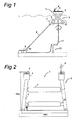
- Figure 1 shows a side view of an embodiment of an overall installation including the wave energy absorber shown in Figure 1 .
- the wave energy absorber 1 is composed, in this particular embodiment, of three expandable elements 2 that are part of a buoyant structure 3 taut moored to the seabed via taut mooring lines 8.
- the deck structure 4 is supported above sea level.
- the open structure members 7 of the buoyant structure 3 are crossing each other so that expandable elements 2 are in a triangle configuration.
- the mooring line angles are selected to optimize the motion of the system.
- the motion of the wave energy absorber 1 should be circular (see the arrow nn Figure 1 ) in order to generate a wave only in the same direction as the incoming wave but with an opposite phase to obtain cancellation.
- the mooring line orientation is also optimized to take into account the distribution of wave incidence angles.
- the taut mooring line 8 is composed of cable (steel or synthetic fibers) for the major part of the water column and a heavy chain 9 near the sea bed.
- the heavy bottom chain weight is selected to maintain minimum tension in the cable when the wave energy absorber 1 is heaving downwards.
- the inclination of the mooring line 8 will preferably be about 45°. This is the preferred orientation as there will be less friction, and the system 1 will be able to do work both during heave and sway. Inclination will be fine-tuned in order to obtain the right natural periods in heave and sway motions.
- the anchors 10 used can be of different types such as vertically loaded anchors, gravity anchors, suction piles, driven piles etc.
- the energy is brought to a cable 11 that will transfer it to a user.
- the cable 11 is placed near the mooring elements so as not to pick up appreciable mooring loads that could cause it to fail.
- the cable has a steep S configuration, in that the cable relies on a buoy 12 lying under the wave active zone that is connected to the seabed.
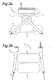
- FIG 2 shows a view of an embodiment of a wave energy absorber 1 according to the present invention.
- the wave energy absorber is composed of several cylindrical expandable elements 2 that are part of a buoyant structure 3 taut moored to the seabed.
- the buoyant structure is composed of a platform or deck 4.
- the deck 4 offers an easy access with a door 5 above the water surface.
- the buoyant structure 3 is also composed of open structure members 7 underneath the deck 4.
- the buoyant structure 3 is composed of two symmetrical parts (each one composed of a deck and open structures) linked together by a support structure 24 to which the expandable elements 2 are fixed.
- the distance between the two symmetrical parts of the 15 buoyant structure 3 is about 16 meters and the height of the buoyant structure 3 is about 15 meters.
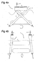
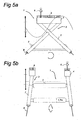
- Figures 3a to 5b show different views of a wave energy absorber according to the invention, in different wave sea states.
- the system according to the invention combines the most efficient operating principle at all wave's frequencies. This can be realized by having a fixed structure and a variable volume, or by having a fixed volume and a variable draft.
- the purpose of the invention is to decrease the wave load on the system to withstand heavy sea states with one and the same mooring system.
- Figures 3a and 3b show different views of a wave energy absorber according to the invention in a heave wave sea state.
- the height of the waves is approximately 1 meter, the period of the wave is less than 10 seconds.
- the cylindrical expandable elements 2 will be fully inflated (diameter about 5 meters) and the system will cut the water plane area and acts as a point absorber (almost behaving like a SPAR buoy, see arrow).
- the configuration of the wave energy absorber 1 is the same as the one described in Figures 1 and 2 .
- Figures 4a and 4b show different views of a wave energy absorber according to the invention in a high wave sea state.
- the height of the waves is about 3 meters; the period of the wave is about 7 to 15 seconds.
- the bladder will deflate (diameter about 3 meters) so that the system will be completely submerged and the system will behave more and more like a Bristol cylinder.
- the configuration of the wave energy absorber 1 is the same as the one described in Figures 1 and 2 .
- Figures 5a and 5b show different views of a wave energy absorber according to the invention in a survival state.
- the height of the waves is about 20 meters; the period of the wave is 15 about 18 seconds.
- the expandable elements 2 will be completely deflated (diameter about 1,7 meter), the system being a frame like structure much more transparent to waves.
- the survival system is completely passive. The importance of the reliability of the valves used is therefore crucial.
- plastic valves are used. The advantage of such valves is that no marine life can set the inside.
- the expandable elements 2 are fitted with fail safe valves (not shown) that will open if a preset maximum extension is reached in one of the mooring line 8. As the expandable elements are pressure inflated, the fluid contained in the expandable elements will be passively flushed by the expandable element skin restoring its potential elastic energy. When the extension in all the mooring lines 8 are falling bellow a preset minimum extension, a pump is used to inflate the expandable elements 2 to increase the volume and thus the wave loads.
- the pump is directly actuated by the mooring line 8, so that the system uses the wave energy to inflate again its expandable elements 2.
- This can be achieved by a separate simple reliable hydraulic pump (for ex. diaphragm or reciprocal) or by the main power take off system driving an electrical pump.
- the power take off (PTO) system will be described in further detail below.
- the expandable elements may be used as a pressure reservoir.
- the volume control system may be used to constantly optimize the volume of the expandable elements according to the incident wave energy.
- the system is self-limiting the load on mooring lines 8 and naturally makes the best use of the available PTO extension range.
- the expandable elements 2 can be made of a non-elastic skin.
- the expandable elements are fitted with spring loaded appendages that arrange the skin in such a manner that the expandable elements once emptied, offer minimal surface and volume to external flow.
- the spring appendages are activated by the pressurization of the expandable elements. Hence, the volume reduction in case of excessive mooring line extension remains passive. Arrangement can consist in (but are not limited to) folding, rolling-up, bellows.
- the spring loaded appendages can be (but are not limited to) elastic rings, stretchers, pneumatic elements etc. and can either be external or internal to the expandable elements. Fail safe valves and pump arrangements remain similar.
- Expandable elements 2 can be fenders, which would present a further advantage of having a new use of a well-proven technology. More details on the expandable elements are given below, see figures 9 and 10 .
- Figures 6a and 6b show side views of different embodiments of a control mechanism of the wave energy absorber shown in Figure 2 .
- Figures 6c and 6d show different views of another embodiment of a control mechanism of the wave energy absorber.
- a spring type actuator is shown, with a spring 15 that can provide a large elongation and which is placed in an easily accessible part of the system. It could be an elastomeric spring, of the kind made by SEAFLEX. This spring will be linked to the mooring lines 8 via a power take off cable 16 that will pass via a sprocket 20. The actuator will be interconnected to the sprocket 20 so that it will react depending on the load exerted on the spring 15.
- the power take off (PTO) system 14 is inside the buoyant structure 3.
- the PTO system 14 is using the extension of the taut mooring system 8 under wave loads.
- the PTO can also be used as an actuator to control and optimize power production (several known control techniques may be used, such as reactive control, phase control, latching). It may use a combination of different systems such as electromechanical system, electro-active polymer system, hydraulic systems, mechanical systems or piezo-electric systems (this list being non-limitative).
- One generator 13 is connected directly at the end of each taut mooring line 8. It allows large extensions and contractions of the mooring lines through a soft spring 15 and damper arrangement. The extensions/contractions are large enough to allow the system to undergo the maximum wave-induced motions in operational and survival conditions without reaching a sudden increase in the rigidity of the mooring lines 8.
- An alternative is to propose the use of stretchable dielectric materials (such as Electro Active Polymers) as generators and actuators to apply the required control strategy. These stretchable dielectric materials have the capacity to stretch considerably and have the required high power density.
- the control mechanism is located in the deck 4 of the buoyant structure 3.
- the PTO 14 is a hydraulic actuator.
- the access to the control mechanism is easy via the door 5 which is above water level on the deck 4.
- the cable 16 linking the mooring line 8 to the spring 15 can be partly made of chain steel cable to minimize the fatigue due to the friction at the sprocket 20 level.
- control mechanism is located in the open structure members 7 of 30 the buoyant structure 3. In this configuration there are no fatigue issues, but the access to the PTO 14 and spring arrangement 15 is less practical than in figure 6a . The access to the power unit control 18 and the pumping device 19 is still easy as they are still located in the deck 4 of the buoyant structure 3.
- the wave energy absorber 1 is composed of three cylindrical expandable elements 2 that are part of a buoyant structure 3 taut moored to the seabed.
- the three expandable elements are disposed each at an apex of a triangle as seen in Figure 6c (front view).
- the buoyant structure is composed of a platform or deck 4.
- the deck 4 offers an easy access with a door 5 above surface water.
- the buoyant structure 3 is also composed of open structure members 7 underneath the deck 4.
- the deck 4 and the two symmetrical open structure members 7 intersect at the level of the upper expandable element 2.
- the control mechanism is located in the deck 4 of the buoyant structure 3.
- the access to the control mechanism is really easy via the door 5.
- the cable 16 can be partly made of chain steel cable to minimize the fatigue due to the friction at the sprockets 20 level.
- Figure 7 shows another embodiment according to the present invention with an alternative arrangement of the mooring lines 8, of a wave energy absorber 1.
- the wave energy absorber is composed of several cylindrical expandable elements 2 that are part of a buoyant structure 3 taut moored to the seabed.
- the buoyant structure is composed of a platform or deck 4.
- the buoyant structure 3 is also composed of open structure members 7 underneath the deck 4.
- hose pumps 22 In order to reinforce the control of the variable tension applied to the mooring line, the present invention proposes to use hose pumps 22.
- hose-pump made of several hose strings 21, is a slender hollow elastic cylinder capable of pumping fluid when it is extended and contracted.
- wave action can be harnessed to produce pressurized fluid via cyclic extensions.
- An inlet valve at the bottom enables to fill the pump hose with a determined amount of water. Water is incompressible and, hence, when the tension on the mooring lines increases, and the water cannot be extracted from hose strings 21, the longitudinal stiffness of the pump hose will increase.
- the hose string may be split in two parts, for instance one part that is used as a hose pump to run a turbine to generate power.
- the other part is fitted with the pressure relief valve and serves as a tension limiter as explained above.
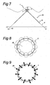
- Figure 8 shows a front view of another embodiment of the use of expandable elements to form a cylinder of trapped water in a heave wave sea state.
- the Bristol cylinder will not be the expandable element 2 filled with a fluid, but a cylinder of trapped sea water 28, the surface of the cylinder being composed of several expandable elements 2 disposed in a circle. When inflated the expandable elements are in contact one with another so that an important volume of sea water is trapped.
- This particular configuration enables to create a Bristol cylinder that can have a diameter of about 12 meters, which is much bigger than the 5 meters obtained with the embodiment shown in Figure 3b .
- FIG 9 shows the same embodiment as in figure 8 but in a survival sea state
- each expandable element 2 is provided with a pressure relief valve that will open when a preset maximum tension force is reached in one of the mooring lines 8. Once deflated, the expandable elements are not in contact with one another, so the trapped sea water can flow.
- the structure will be rather transparent to wave loads and the tension that is applied on the mooring lines 8 will not lead to failure.
- FIG 10 shows an embodiment of an expandable element 2 used in the present invention when deflated.
- the expandable element skin sticks to the support structure 24.
- the support structure has a larger diameter in the middle. Due to its elasticity of the expandable element skin and to the configuration of the support structure even after several cycles of inflation and deflation (leading to creeping and bending in of the extendable element 2), the expandable element skin is always tightly in contact with the support structure when the expandable element is deflated.
- each extremity of the expandable element has sliding flanges or rings 25.
- There are other fixed flanges 27 that can be for example bolted to the support structure 24. Between the slidable flanges 25 and the fixed flanges 27 there is an expansion joint or below 26 that can accommodate the longitudinal dilation of the expandable element 2 when inflating.
- Figure 11 shows the expandable element 2 of figure 9 when inflated.
- a fluid 26 is injected through the supporting structures 24.
- the internal pressure in the expandable element 2 increases.
- the expandable elements will inflate.
- the diameter of the expandable element will increase, therefore it will expand in the radial direction and hence it will shrink in the longitudinal direction.
- the expandable element 2 will be in tight contact with the support structure 24 (even after several cycles of inflating/deflating). This is due in part to the elasticity of the material used but also to the fact that once stretched the bellows become spring loaded.
- the internal pressure can be maintained for example by means of closed valves or via a continuous injection of liquid.
- the wave energy absorber system according to the present invention can also be designed as a bundle of several structures as the one shown in the described figures. To optimize the efficiency of the system, the distance between each structure is predetermined.
- the Froude-Krylov force is the force introduced by the unsteady pressure field generated by undisturbed waves (FK).
- the Froude-Krylov force is together with the diffraction force the total non-viscous forces acting on a floating body in regular waves.
- the diffraction force is due to the floating body disturbing the waves.
- the total FK on several buoyant structures arranged in a bundle is equal to the sum of the FK on each buoyant structure, but the diffraction force on several buoyant structures arranged in a bundle is greater than the sum of the diffraction forces on each buoyant structure due to constructive interferences between the structures.
- the total non-viscous forces will be higher with a configuration of several buoyant structures arranged in a bundle (with regards to a configuration of one big buoyant structure), hence this configuration will provide a higher energy.
Landscapes
- Engineering & Computer Science (AREA)
- Chemical & Material Sciences (AREA)
- Combustion & Propulsion (AREA)
- Mechanical Engineering (AREA)
- General Engineering & Computer Science (AREA)
- Other Liquid Machine Or Engine Such As Wave Power Use (AREA)
Claims (23)
- Unité houlomotrice pour extraire d'une façon efficace de l'énergie des vagues sur une surface d'eau dans différentes conditions en mer, comportant une structure flottante principale (3) amarrée au fond marin avec des lignes d'amarrage tendues (8) et placée à une profondeur submergée et active de vague, un générateur linéaire (13) placé dans la structure flottante (3) et activé par l'intermédiaire d'une ligne d'amarrage tendue (8), une unité de commande de puissance (18) et un câble de prise de force (15) connecté au générateur linéaire (13) et menant, par l'intermédiaire du fond marin au rivage, caractérisée en ce que la structure flottante (3) est pourvue d'un moyen pour faire varier la surface de la structure flottante (3) qui est exposée à la pression dynamique de la vague par gonflage/dégonflage comprenant un élément expansible (2) avec une géométrie variable pour une prise de force efficace pour plus d'une fréquence de vague et pour commander la tension dans les lignes d'amarrage tendues (8).
- Unité houlomotrice selon la revendication 1, caractérisée en ce que la structure flottante principale (3) comprend de multiples éléments expansibles (2).
- Unité houlomotrice selon la revendication 2, caractérisée en ce que les multiples éléments expansibles allongés (2) sont placés selon un agencement cylindrique.
- Unité houlomotrice selon l'une des revendications précédentes, caractérisée en ce que l'élément expansible allongé (2) est une vessie allongée qui peut être remplie d'un fluide pour augmenter la surface effective de l'élément expansible.
- Unité houlomotrice selon l'une des revendications précédentes, caractérisée en ce que le moyen pour faire varier la surface de la structure flottante (3) est activé par une unité de commande de puissance (18).
- Unité houlomotrice selon l'une des revendications précédentes, caractérisée en ce que le système de prise de force (14) est placé dans l'environnement sec de la structure flottante (3).
- Unité houlomotrice selon l'une des revendications précédentes, caractérisée en ce que l'unité de commande de puissance (18) est placée dans l'environnement sec de la structure flottante principale.
- Unité houlomotrice selon l'une des revendications précédentes, caractérisée en ce que la structure flottante (3) est pourvue d'au moins une partie (4) qui fait saillie à la surface de la mer.
- Unité houlomotrice selon l'une des revendications précédentes, caractérisée en ce que la partie saillante (4) est pourvue d'une porte (5) au-dessus de la surface d'eau, de façon à permettre l'accès à l'intérieur de la structure flottante principale (3).
- Unité houlomotrice selon l'une des revendications précédentes, caractérisée en ce que la structure flottante (3) est pourvue d'au moins deux ensembles de lignes d'amarrage tendues inclinées (8), chacun des ensembles étant constitué d'au moins deux lignes d'amarrage tendues (8) dont les axes se croisent près de la structure flottante (3).
- Unité houlomotrice selon l'une des revendications précédentes, caractérisée en ce que la ligne d'amarrage tendue est pourvue d'un élément d'extension.
- Unité houlomotrice selon l'une des revendications précédentes, caractérisée en ce que la ligne d'amarrage tendue est pourvue d'un poids de lestage (9).
- Unité houlomotrice selon l'une des revendications précédentes, caractérisée en ce que l'élément expansible (2) est réalisé en un matériau diélectrique étirable pour générer de l'électricité pendant des variations de surface de l'élément expansible (2).
- Unité houlomotrice selon l'une des revendications précédentes, caractérisée en ce que l'élément expansible (2) est pourvu d'une soupape de surpression.
- Unité houlomotrice selon la revendication 12, caractérisée en ce que la soupape de surpression s'ouvre lorsqu'une force de tension maximale préétablie est atteinte dans l'une des lignes d'amarrage (8).
- Unité houlomotrice selon l'une des revendications précédentes, caractérisée en ce que lorsque la tension dans une ou plusieurs ligne(s) d'amarrage (8) est inférieure à un minimum préétabli, un dispositif de pompage (19) est utilisé pour augmenter le volume des éléments expansibles (2) et ainsi la surface effective de la structure flottante (3).
- Unité houlomotrice selon l'une des revendications précédentes, caractérisée en ce que le dispositif de pompage (19) est actionné par l'électricité produite par l'unité houlomotrice.
- Unité houlomotrice selon l'une des revendications précédentes, caractérisée en ce que l'élément expansible (2) peut être pourvu d'un appendice à ressort (15) qui est activé par la pressurisation de l'élément expansible (2).
- Unité houlomotrice selon l'une des revendications précédentes, caractérisée en ce que l'élément expansible (2) est gonflé et/ou dégonflé en utilisant des matériaux diélectriques étirables.
- Unité houlomotrice selon l'une des revendications précédentes, caractérisée en ce que l'élément expansible (2) est fixé à une structure de support (24) par l'intermédiaire d'une bride coulissante (25) et la surface est maintenue en contact étroit avec la structure de support (2).
- Unité houlomotrice selon l'une des revendications précédentes, caractérisée en ce que l'élément expansible (2) est fixé à une structure de support par l'intermédiaire d'une bride coulissante (25) et d'un soufflet à ressort (26), le soufflet étant étiré pour s'adapter au retrait dans la direction longitudinale de l'élément expansible (2) lorsqu'il est gonflé.
- Système absorbeur de l'énergie des vagues selon l'une des revendications précédentes, caractérisé en ce que plusieurs structures flottantes (3) sont agencées selon une configuration de faisceau, la distance entre chaque structure flottante (3) étant prédéterminée.
- Système absorbeur de l'énergie des vagues selon l'une des revendications précédentes, caractérisé en ce qu'il présente une conception modulaire.
Priority Applications (3)
| Application Number | Priority Date | Filing Date | Title |
|---|---|---|---|
| EP10177670.6A EP2256337B1 (fr) | 2008-01-14 | 2009-01-14 | Générateur d'énergie à base de vagues |
| EP09702345.1A EP2232057B1 (fr) | 2008-01-14 | 2009-01-14 | Absorbeur de l'énergie des vagues |
| DK10177670.6T DK2256337T3 (da) | 2008-01-14 | 2009-01-14 | Bølgeenergigenerator |
Applications Claiming Priority (4)
| Application Number | Priority Date | Filing Date | Title |
|---|---|---|---|
| EP08100411 | 2008-01-14 | ||
| EP08165267 | 2008-09-26 | ||
| EP09702345.1A EP2232057B1 (fr) | 2008-01-14 | 2009-01-14 | Absorbeur de l'énergie des vagues |
| PCT/EP2009/050390 WO2009090192A2 (fr) | 2008-01-14 | 2009-01-14 | Absorbeur de l'énergie des vagues |
Related Child Applications (1)
| Application Number | Title | Priority Date | Filing Date |
|---|---|---|---|
| EP10177670.6A Division-Into EP2256337B1 (fr) | 2008-01-14 | 2009-01-14 | Générateur d'énergie à base de vagues |
Publications (2)
| Publication Number | Publication Date |
|---|---|
| EP2232057A2 EP2232057A2 (fr) | 2010-09-29 |
| EP2232057B1 true EP2232057B1 (fr) | 2015-09-16 |
Family
ID=40885694
Family Applications (2)
| Application Number | Title | Priority Date | Filing Date |
|---|---|---|---|
| EP09702345.1A Not-in-force EP2232057B1 (fr) | 2008-01-14 | 2009-01-14 | Absorbeur de l'énergie des vagues |
| EP10177670.6A Active EP2256337B1 (fr) | 2008-01-14 | 2009-01-14 | Générateur d'énergie à base de vagues |
Family Applications After (1)
| Application Number | Title | Priority Date | Filing Date |
|---|---|---|---|
| EP10177670.6A Active EP2256337B1 (fr) | 2008-01-14 | 2009-01-14 | Générateur d'énergie à base de vagues |
Country Status (6)
| Country | Link |
|---|---|
| US (1) | US8421259B2 (fr) |
| EP (2) | EP2232057B1 (fr) |
| CN (1) | CN101946088A (fr) |
| AU (1) | AU2009204866A1 (fr) |
| DK (1) | DK2256337T3 (fr) |
| WO (1) | WO2009090192A2 (fr) |
Families Citing this family (31)
| Publication number | Priority date | Publication date | Assignee | Title |
|---|---|---|---|---|
| JP5604310B2 (ja) * | 2008-02-20 | 2014-10-08 | オーシャン・ハーベスティング・テクノロジーズ・エイビイ | 波力エネルギープラント |
| EP2274515B1 (fr) * | 2008-02-29 | 2016-03-23 | Single Buoy Moorings Inc. | Système d'exploitation combinée de l'énergie du vent et des vagues en mer |
| JP2012505349A (ja) * | 2008-10-09 | 2012-03-01 | イー・アイ・デュポン・ドウ・ヌムール・アンド・カンパニー | 波力エネルギー変換装置 |
| US9526418B2 (en) * | 2008-12-04 | 2016-12-27 | Deep Science, Llc | Device for storage of intraluminally generated power |
| US20100140958A1 (en) * | 2008-12-04 | 2010-06-10 | Searete Llc, A Limited Liability Corporation Of The State Of Delaware | Method for powering devices from intraluminal pressure changes |
| US9759202B2 (en) * | 2008-12-04 | 2017-09-12 | Deep Science, Llc | Method for generation of power from intraluminal pressure changes |
| US9353733B2 (en) * | 2008-12-04 | 2016-05-31 | Deep Science, Llc | Device and system for generation of power from intraluminal pressure changes |
| US9567983B2 (en) * | 2008-12-04 | 2017-02-14 | Deep Science, Llc | Method for generation of power from intraluminal pressure changes |
| US9631610B2 (en) | 2008-12-04 | 2017-04-25 | Deep Science, Llc | System for powering devices from intraluminal pressure changes |
| JP5805753B2 (ja) * | 2010-05-28 | 2015-11-04 | シーベイスト アクチボラグSeabased AB | 波力発電装置、その使用、及び、電気エネルギー生成方法 |
| FI122687B (fi) * | 2010-07-15 | 2012-05-31 | Wello Oy | Aaltovoimala |
| AU2012262997B2 (en) | 2011-06-03 | 2017-01-19 | Ocean Harvesting Technologies Ab | Wave energy converter |
| WO2013029012A1 (fr) * | 2011-08-25 | 2013-02-28 | Resolute Marine Energy, Inc. | Commande optimisée de convertisseurs d'énergie des vagues à multiples prises de force (pto) |
| US8456028B1 (en) * | 2012-02-06 | 2013-06-04 | Elwha Llc | Method and apparatus for storing energy |
| US8823196B1 (en) * | 2013-08-05 | 2014-09-02 | Donald H Gehring | Apparatus of wave generators and a mooring system to generate electricity |
| US9166242B2 (en) | 2013-08-13 | 2015-10-20 | The United States Of America, As Represented By The Secretary Of The Navy | Multi-modal energy harvester |
| US9726143B2 (en) * | 2014-04-07 | 2017-08-08 | University Of Manitoba | Ocean wave energy harvesting with a piezoelectric coupled buoy |
| US9709142B2 (en) | 2014-04-09 | 2017-07-18 | Brimes Energy, Inc. | Wave energy conversion system |
| KR101543995B1 (ko) * | 2014-04-10 | 2015-08-13 | 도널드 에이치 게링 | 전기를 발생하기 위한 파도 발생기 및 계류 시스템의 장치 |
| US10309367B2 (en) * | 2014-06-04 | 2019-06-04 | Mitchell Fait | Systems and methods for obtaining energy from surface waves |
| DE102014111929B4 (de) | 2014-08-20 | 2017-12-07 | Fraunhofer-Gesellschaft zur Förderung der angewandten Forschung e.V. | Verfahren zum direkten Umwandeln von kinetischer Energie einer strömenden Flüssigkeit in elektrische Energie und Vorrichtung hierfür |
| WO2017189455A1 (fr) | 2016-04-24 | 2017-11-02 | The Regents Of The University Of California | Houlomotrice submergée pour fonctionnement en eaux profondes et peu profondes |
| SE540263C2 (en) * | 2016-06-13 | 2018-05-15 | Novige Ab | Apparatus for harvesting energy from waves |
| EP3324037A3 (fr) * | 2016-10-31 | 2018-07-18 | Ocean Harvesting Technologies AB | Dispositif de prise de force |
| CN106762373A (zh) * | 2017-01-12 | 2017-05-31 | 集美大学 | 一种同时利用波浪能和潮流能的漂浮式海洋能发电装置 |
| US10352290B2 (en) * | 2017-02-14 | 2019-07-16 | The Texas A&M University System | Method and apparatus for wave energy conversion |
| US11002243B2 (en) | 2017-04-24 | 2021-05-11 | The Regents Of The University Of California | Submerged wave energy converter for deep water operations |
| US20190032626A1 (en) * | 2017-07-28 | 2019-01-31 | Fan Liu | Wave Power Generator |
| GB202017475D0 (en) * | 2020-11-04 | 2020-12-16 | Marine Power Systems Ltd | Wave energy absorber with adjustable hydrodynamic properties |
| CN115614243B (zh) * | 2022-10-13 | 2025-08-08 | 中国科学院广州能源研究所 | 一种双向液压阻尼能量吸收式抗台系泊系统 |
| CN116654225B (zh) * | 2023-02-22 | 2026-02-17 | 国家深海基地管理中心 | 一种载人潜水器应急救援装置及方法 |
Family Cites Families (25)
| Publication number | Priority date | Publication date | Assignee | Title |
|---|---|---|---|---|
| FR359932A (fr) * | 1904-12-12 | 1906-04-07 | John Hutchings | Appareil produisant de la force motrice par l'utilisation du mouvement des marées et des vagues |
| US3197963A (en) * | 1960-07-19 | 1965-08-03 | Univ Minnesota | Wave attenuator |
| GB2007314B (en) * | 1977-10-13 | 1982-03-24 | British Petroleum Co | Wave energy device |
| DE2844809A1 (de) * | 1978-10-12 | 1980-04-24 | Jander Dieter Dipl Ing | Vorrichtung zur umwandlung der energie von meereswellen in elektrische energie |
| DE3419565A1 (de) | 1984-05-25 | 1985-11-28 | Rolf Dr. 5090 Leverkusen Brück | Vorrichtung zur erzeugung von energie aus meereswellen |
| US4754157A (en) * | 1985-10-01 | 1988-06-28 | Windle Tom J | Float type wave energy extraction apparatus and method |
| GB9207810D0 (en) | 1992-04-09 | 1992-05-27 | Hyatt Anne | Apparatus for harnessing tidal power |
| US5842838A (en) * | 1996-11-04 | 1998-12-01 | Berg; John L. | Stable wave motor |
| US6809462B2 (en) * | 2000-04-05 | 2004-10-26 | Sri International | Electroactive polymer sensors |
| US6229225B1 (en) * | 1997-05-08 | 2001-05-08 | Ocean Power Technologies, Inc. | Surface wave energy capture system |
| WO1999028623A1 (fr) | 1997-12-03 | 1999-06-10 | William Dick | Houlomotrice |
| IES20000493A2 (en) | 2000-06-16 | 2002-02-06 | Wavebob Ltd | Wave energy converter |
| ES2170029B1 (es) * | 2000-12-11 | 2003-11-01 | Molina Jose Antonio Serrano | Sistema de generacion de energia a partir de las olas del mar. |
| GB0205732D0 (en) * | 2001-03-16 | 2002-04-24 | Sanchez Gomez Gines | Floating platform to obtain electric power from the sea waves |
| SE520921C2 (sv) * | 2002-01-10 | 2003-09-16 | Swedish Seabased Energy Ab | Vågkraftaggregat, användning av ett vågkraftaggregat, förfarande för att genera elektrisk energi, system av komponenter för tillverkning av linjärgenerator till ett vågkraftaggregat samt förfarnde vid tillverkning av en linjärgenerator |
| DE20312348U1 (de) * | 2003-08-12 | 2004-04-01 | Suthoff, Burkhard, Prof. Dr.Dr. | Wellenmotor |
| NO20033807D0 (no) * | 2003-08-27 | 2003-08-27 | Norsk Hydro As | Vindmölle for anvendelse offshore |
| ES2238167B1 (es) * | 2003-11-28 | 2007-12-16 | Arlas Invest, S.L. | Sistema de generacion de energia a partir de la olas del mar. |
| US7319278B2 (en) * | 2005-06-01 | 2008-01-15 | Donald Hollis Gehring | Ocean wave generation |
| US7498685B2 (en) * | 2005-11-09 | 2009-03-03 | Timothy John Emmanuel Turner | Electrical generator |
| GB2434840B (en) * | 2006-02-04 | 2011-10-19 | Francis James Macdonald Farley | Distensible tube wave energy converter |
| US7557456B2 (en) | 2006-05-05 | 2009-07-07 | Sri International | Wave powered generation using electroactive polymers |
| US7245041B1 (en) | 2006-05-05 | 2007-07-17 | Olson Chris F | Ocean wave energy converter |
| US7538445B2 (en) | 2006-05-05 | 2009-05-26 | Sri International | Wave powered generation |
| US20100244451A1 (en) * | 2009-03-30 | 2010-09-30 | Ahdoot Ned M | Ocean wave energy to electricity generator |
-
2009
- 2009-01-14 WO PCT/EP2009/050390 patent/WO2009090192A2/fr not_active Ceased
- 2009-01-14 EP EP09702345.1A patent/EP2232057B1/fr not_active Not-in-force
- 2009-01-14 DK DK10177670.6T patent/DK2256337T3/da active
- 2009-01-14 US US12/812,765 patent/US8421259B2/en not_active Expired - Fee Related
- 2009-01-14 AU AU2009204866A patent/AU2009204866A1/en not_active Abandoned
- 2009-01-14 CN CN2009801051633A patent/CN101946088A/zh active Pending
- 2009-01-14 EP EP10177670.6A patent/EP2256337B1/fr active Active
Also Published As
| Publication number | Publication date |
|---|---|
| US8421259B2 (en) | 2013-04-16 |
| EP2256337B1 (fr) | 2013-08-14 |
| WO2009090192A3 (fr) | 2010-06-17 |
| DK2256337T3 (da) | 2013-11-11 |
| EP2232057A2 (fr) | 2010-09-29 |
| WO2009090192A2 (fr) | 2009-07-23 |
| EP2256337A1 (fr) | 2010-12-01 |
| AU2009204866A1 (en) | 2009-07-23 |
| CN101946088A (zh) | 2011-01-12 |
| US20110062713A1 (en) | 2011-03-17 |
Similar Documents
| Publication | Publication Date | Title |
|---|---|---|
| EP2232057B1 (fr) | Absorbeur de l'énergie des vagues | |
| US9309860B2 (en) | Wave energy conversion device | |
| US9297352B2 (en) | Energy converter | |
| US9523346B2 (en) | Modular array type energy converter | |
| US7339285B2 (en) | Hydroelectric wave-energy conversion system | |
| EP2245299B1 (fr) | Appareil de conversion de l'énergie des vagues | |
| JP2008536045A (ja) | 波力装置を備えた設備及びそのサポート構造 | |
| JP2012514708A (ja) | 海洋波エネルギーを電気に変換する方法及び装置 | |
| JP2007508488A (ja) | フロートと海面より上の位置にフロートを固定する手段とを持つ波発電装置 | |
| GB2540615A (en) | Wave energy converter | |
| EP2501926B1 (fr) | Pompes | |
| EP2678554A1 (fr) | Absorbeur d'énergie houlomotrice | |
| US12473886B2 (en) | Two body variable ballast wave energy converter | |
| US20230383720A1 (en) | Wave energy absorber with adjustable hydrodynamic properties | |
| WO2025125398A1 (fr) | Convertisseur d'énergie houlomotrice |
Legal Events
| Date | Code | Title | Description |
|---|---|---|---|
| PUAI | Public reference made under article 153(3) epc to a published international application that has entered the european phase |
Free format text: ORIGINAL CODE: 0009012 |
|
| 17P | Request for examination filed |
Effective date: 20100714 |
|
| AK | Designated contracting states |
Kind code of ref document: A2 Designated state(s): AT BE BG CH CY CZ DE DK EE ES FI FR GB GR HR HU IE IS IT LI LT LU LV MC MK MT NL NO PL PT RO SE SI SK TR |
|
| AX | Request for extension of the european patent |
Extension state: AL BA RS |
|
| DAX | Request for extension of the european patent (deleted) | ||
| GRAP | Despatch of communication of intention to grant a patent |
Free format text: ORIGINAL CODE: EPIDOSNIGR1 |
|
| INTG | Intention to grant announced |
Effective date: 20150415 |
|
| GRAS | Grant fee paid |
Free format text: ORIGINAL CODE: EPIDOSNIGR3 |
|
| GRAA | (expected) grant |
Free format text: ORIGINAL CODE: 0009210 |
|
| AK | Designated contracting states |
Kind code of ref document: B1 Designated state(s): AT BE BG CH CY CZ DE DK EE ES FI FR GB GR HR HU IE IS IT LI LT LU LV MC MK MT NL NO PL PT RO SE SI SK TR |
|
| REG | Reference to a national code |
Ref country code: GB Ref legal event code: FG4D |
|
| REG | Reference to a national code |
Ref country code: CH Ref legal event code: EP |
|
| REG | Reference to a national code |
Ref country code: IE Ref legal event code: FG4D |
|
| REG | Reference to a national code |
Ref country code: AT Ref legal event code: REF Ref document number: 750032 Country of ref document: AT Kind code of ref document: T Effective date: 20151015 |
|
| REG | Reference to a national code |
Ref country code: DE Ref legal event code: R096 Ref document number: 602009033651 Country of ref document: DE |
|
| REG | Reference to a national code |
Ref country code: NL Ref legal event code: MP Effective date: 20150916 |
|
| PG25 | Lapsed in a contracting state [announced via postgrant information from national office to epo] |
Ref country code: GR Free format text: LAPSE BECAUSE OF FAILURE TO SUBMIT A TRANSLATION OF THE DESCRIPTION OR TO PAY THE FEE WITHIN THE PRESCRIBED TIME-LIMIT Effective date: 20151217 Ref country code: LV Free format text: LAPSE BECAUSE OF FAILURE TO SUBMIT A TRANSLATION OF THE DESCRIPTION OR TO PAY THE FEE WITHIN THE PRESCRIBED TIME-LIMIT Effective date: 20150916 Ref country code: LT Free format text: LAPSE BECAUSE OF FAILURE TO SUBMIT A TRANSLATION OF THE DESCRIPTION OR TO PAY THE FEE WITHIN THE PRESCRIBED TIME-LIMIT Effective date: 20150916 Ref country code: NO Free format text: LAPSE BECAUSE OF FAILURE TO SUBMIT A TRANSLATION OF THE DESCRIPTION OR TO PAY THE FEE WITHIN THE PRESCRIBED TIME-LIMIT Effective date: 20151216 Ref country code: FI Free format text: LAPSE BECAUSE OF FAILURE TO SUBMIT A TRANSLATION OF THE DESCRIPTION OR TO PAY THE FEE WITHIN THE PRESCRIBED TIME-LIMIT Effective date: 20150916 |
|
| REG | Reference to a national code |
Ref country code: LT Ref legal event code: MG4D |
|
| REG | Reference to a national code |
Ref country code: AT Ref legal event code: MK05 Ref document number: 750032 Country of ref document: AT Kind code of ref document: T Effective date: 20150916 |
|
| PG25 | Lapsed in a contracting state [announced via postgrant information from national office to epo] |
Ref country code: SE Free format text: LAPSE BECAUSE OF FAILURE TO SUBMIT A TRANSLATION OF THE DESCRIPTION OR TO PAY THE FEE WITHIN THE PRESCRIBED TIME-LIMIT Effective date: 20150916 Ref country code: HR Free format text: LAPSE BECAUSE OF FAILURE TO SUBMIT A TRANSLATION OF THE DESCRIPTION OR TO PAY THE FEE WITHIN THE PRESCRIBED TIME-LIMIT Effective date: 20150916 |
|
| PG25 | Lapsed in a contracting state [announced via postgrant information from national office to epo] |
Ref country code: NL Free format text: LAPSE BECAUSE OF FAILURE TO SUBMIT A TRANSLATION OF THE DESCRIPTION OR TO PAY THE FEE WITHIN THE PRESCRIBED TIME-LIMIT Effective date: 20150916 |
|
| PG25 | Lapsed in a contracting state [announced via postgrant information from national office to epo] |
Ref country code: IT Free format text: LAPSE BECAUSE OF FAILURE TO SUBMIT A TRANSLATION OF THE DESCRIPTION OR TO PAY THE FEE WITHIN THE PRESCRIBED TIME-LIMIT Effective date: 20150916 Ref country code: CZ Free format text: LAPSE BECAUSE OF FAILURE TO SUBMIT A TRANSLATION OF THE DESCRIPTION OR TO PAY THE FEE WITHIN THE PRESCRIBED TIME-LIMIT Effective date: 20150916 Ref country code: EE Free format text: LAPSE BECAUSE OF FAILURE TO SUBMIT A TRANSLATION OF THE DESCRIPTION OR TO PAY THE FEE WITHIN THE PRESCRIBED TIME-LIMIT Effective date: 20150916 Ref country code: IS Free format text: LAPSE BECAUSE OF FAILURE TO SUBMIT A TRANSLATION OF THE DESCRIPTION OR TO PAY THE FEE WITHIN THE PRESCRIBED TIME-LIMIT Effective date: 20160116 Ref country code: SK Free format text: LAPSE BECAUSE OF FAILURE TO SUBMIT A TRANSLATION OF THE DESCRIPTION OR TO PAY THE FEE WITHIN THE PRESCRIBED TIME-LIMIT Effective date: 20150916 Ref country code: ES Free format text: LAPSE BECAUSE OF FAILURE TO SUBMIT A TRANSLATION OF THE DESCRIPTION OR TO PAY THE FEE WITHIN THE PRESCRIBED TIME-LIMIT Effective date: 20150916 |
|
| PG25 | Lapsed in a contracting state [announced via postgrant information from national office to epo] |
Ref country code: PL Free format text: LAPSE BECAUSE OF FAILURE TO SUBMIT A TRANSLATION OF THE DESCRIPTION OR TO PAY THE FEE WITHIN THE PRESCRIBED TIME-LIMIT Effective date: 20150916 Ref country code: AT Free format text: LAPSE BECAUSE OF FAILURE TO SUBMIT A TRANSLATION OF THE DESCRIPTION OR TO PAY THE FEE WITHIN THE PRESCRIBED TIME-LIMIT Effective date: 20150916 Ref country code: PT Free format text: LAPSE BECAUSE OF FAILURE TO SUBMIT A TRANSLATION OF THE DESCRIPTION OR TO PAY THE FEE WITHIN THE PRESCRIBED TIME-LIMIT Effective date: 20160118 Ref country code: RO Free format text: LAPSE BECAUSE OF FAILURE TO SUBMIT A TRANSLATION OF THE DESCRIPTION OR TO PAY THE FEE WITHIN THE PRESCRIBED TIME-LIMIT Effective date: 20150916 Ref country code: BE Free format text: LAPSE BECAUSE OF NON-PAYMENT OF DUE FEES Effective date: 20160131 |
|
| REG | Reference to a national code |
Ref country code: DE Ref legal event code: R097 Ref document number: 602009033651 Country of ref document: DE |
|
| PLBE | No opposition filed within time limit |
Free format text: ORIGINAL CODE: 0009261 |
|
| STAA | Information on the status of an ep patent application or granted ep patent |
Free format text: STATUS: NO OPPOSITION FILED WITHIN TIME LIMIT |
|
| REG | Reference to a national code |
Ref country code: DE Ref legal event code: R119 Ref document number: 602009033651 Country of ref document: DE |
|
| 26N | No opposition filed |
Effective date: 20160617 |
|
| PG25 | Lapsed in a contracting state [announced via postgrant information from national office to epo] |
Ref country code: DK Free format text: LAPSE BECAUSE OF FAILURE TO SUBMIT A TRANSLATION OF THE DESCRIPTION OR TO PAY THE FEE WITHIN THE PRESCRIBED TIME-LIMIT Effective date: 20150916 Ref country code: LU Free format text: LAPSE BECAUSE OF FAILURE TO SUBMIT A TRANSLATION OF THE DESCRIPTION OR TO PAY THE FEE WITHIN THE PRESCRIBED TIME-LIMIT Effective date: 20160114 |
|
| REG | Reference to a national code |
Ref country code: CH Ref legal event code: PL |
|
| GBPC | Gb: european patent ceased through non-payment of renewal fee |
Effective date: 20160114 |
|
| PG25 | Lapsed in a contracting state [announced via postgrant information from national office to epo] |
Ref country code: MC Free format text: LAPSE BECAUSE OF FAILURE TO SUBMIT A TRANSLATION OF THE DESCRIPTION OR TO PAY THE FEE WITHIN THE PRESCRIBED TIME-LIMIT Effective date: 20150916 |
|
| REG | Reference to a national code |
Ref country code: FR Ref legal event code: ST Effective date: 20160930 |
|
| PG25 | Lapsed in a contracting state [announced via postgrant information from national office to epo] |
Ref country code: GB Free format text: LAPSE BECAUSE OF NON-PAYMENT OF DUE FEES Effective date: 20160114 Ref country code: DE Free format text: LAPSE BECAUSE OF NON-PAYMENT OF DUE FEES Effective date: 20160802 Ref country code: LI Free format text: LAPSE BECAUSE OF NON-PAYMENT OF DUE FEES Effective date: 20160131 Ref country code: CH Free format text: LAPSE BECAUSE OF NON-PAYMENT OF DUE FEES Effective date: 20160131 |
|
| REG | Reference to a national code |
Ref country code: IE Ref legal event code: MM4A |
|
| PG25 | Lapsed in a contracting state [announced via postgrant information from national office to epo] |
Ref country code: FR Free format text: LAPSE BECAUSE OF NON-PAYMENT OF DUE FEES Effective date: 20160201 Ref country code: SI Free format text: LAPSE BECAUSE OF FAILURE TO SUBMIT A TRANSLATION OF THE DESCRIPTION OR TO PAY THE FEE WITHIN THE PRESCRIBED TIME-LIMIT Effective date: 20150916 |
|
| PG25 | Lapsed in a contracting state [announced via postgrant information from national office to epo] |
Ref country code: BE Free format text: LAPSE BECAUSE OF FAILURE TO SUBMIT A TRANSLATION OF THE DESCRIPTION OR TO PAY THE FEE WITHIN THE PRESCRIBED TIME-LIMIT Effective date: 20150916 |
|
| PG25 | Lapsed in a contracting state [announced via postgrant information from national office to epo] |
Ref country code: IE Free format text: LAPSE BECAUSE OF NON-PAYMENT OF DUE FEES Effective date: 20160114 |
|
| PG25 | Lapsed in a contracting state [announced via postgrant information from national office to epo] |
Ref country code: MT Free format text: LAPSE BECAUSE OF FAILURE TO SUBMIT A TRANSLATION OF THE DESCRIPTION OR TO PAY THE FEE WITHIN THE PRESCRIBED TIME-LIMIT Effective date: 20150916 |
|
| PG25 | Lapsed in a contracting state [announced via postgrant information from national office to epo] |
Ref country code: HU Free format text: LAPSE BECAUSE OF FAILURE TO SUBMIT A TRANSLATION OF THE DESCRIPTION OR TO PAY THE FEE WITHIN THE PRESCRIBED TIME-LIMIT; INVALID AB INITIO Effective date: 20090114 Ref country code: CY Free format text: LAPSE BECAUSE OF FAILURE TO SUBMIT A TRANSLATION OF THE DESCRIPTION OR TO PAY THE FEE WITHIN THE PRESCRIBED TIME-LIMIT Effective date: 20150916 |
|
| PG25 | Lapsed in a contracting state [announced via postgrant information from national office to epo] |
Ref country code: TR Free format text: LAPSE BECAUSE OF FAILURE TO SUBMIT A TRANSLATION OF THE DESCRIPTION OR TO PAY THE FEE WITHIN THE PRESCRIBED TIME-LIMIT Effective date: 20150916 Ref country code: MT Free format text: LAPSE BECAUSE OF FAILURE TO SUBMIT A TRANSLATION OF THE DESCRIPTION OR TO PAY THE FEE WITHIN THE PRESCRIBED TIME-LIMIT Effective date: 20160131 Ref country code: MK Free format text: LAPSE BECAUSE OF FAILURE TO SUBMIT A TRANSLATION OF THE DESCRIPTION OR TO PAY THE FEE WITHIN THE PRESCRIBED TIME-LIMIT Effective date: 20150916 |
|
| PG25 | Lapsed in a contracting state [announced via postgrant information from national office to epo] |
Ref country code: BG Free format text: LAPSE BECAUSE OF FAILURE TO SUBMIT A TRANSLATION OF THE DESCRIPTION OR TO PAY THE FEE WITHIN THE PRESCRIBED TIME-LIMIT Effective date: 20150916 |
|
| P01 | Opt-out of the competence of the unified patent court (upc) registered |
Effective date: 20230525 |