EP2232090B1 - Lageranordnung - Google Patents
Lageranordnung Download PDFInfo
- Publication number
- EP2232090B1 EP2232090B1 EP09700621A EP09700621A EP2232090B1 EP 2232090 B1 EP2232090 B1 EP 2232090B1 EP 09700621 A EP09700621 A EP 09700621A EP 09700621 A EP09700621 A EP 09700621A EP 2232090 B1 EP2232090 B1 EP 2232090B1
- Authority
- EP
- European Patent Office
- Prior art keywords
- bearing
- support body
- bearing support
- bore
- pin
- Prior art date
- Legal status (The legal status is an assumption and is not a legal conclusion. Google has not performed a legal analysis and makes no representation as to the accuracy of the status listed.)
- Not-in-force
Links
- 238000005461 lubrication Methods 0.000 claims description 6
- 238000005096 rolling process Methods 0.000 description 11
- 238000009826 distribution Methods 0.000 description 6
- 239000000463 material Substances 0.000 description 4
- 230000000712 assembly Effects 0.000 description 3
- 238000000429 assembly Methods 0.000 description 3
- 239000002184 metal Substances 0.000 description 3
- 230000000295 complement effect Effects 0.000 description 2
- 230000000694 effects Effects 0.000 description 2
- 238000003860 storage Methods 0.000 description 2
- 230000015572 biosynthetic process Effects 0.000 description 1
- 230000001419 dependent effect Effects 0.000 description 1
- 230000001627 detrimental effect Effects 0.000 description 1
- 238000004519 manufacturing process Methods 0.000 description 1
- 238000000034 method Methods 0.000 description 1
- 230000007704 transition Effects 0.000 description 1
Images


Classifications
-
- F—MECHANICAL ENGINEERING; LIGHTING; HEATING; WEAPONS; BLASTING
- F16—ENGINEERING ELEMENTS AND UNITS; GENERAL MEASURES FOR PRODUCING AND MAINTAINING EFFECTIVE FUNCTIONING OF MACHINES OR INSTALLATIONS; THERMAL INSULATION IN GENERAL
- F16C—SHAFTS; FLEXIBLE SHAFTS; ELEMENTS OR CRANKSHAFT MECHANISMS; ROTARY BODIES OTHER THAN GEARING ELEMENTS; BEARINGS
- F16C13/00—Rolls, drums, discs, or the like; Bearings or mountings therefor
- F16C13/02—Bearings
-
- B—PERFORMING OPERATIONS; TRANSPORTING
- B21—MECHANICAL METAL-WORKING WITHOUT ESSENTIALLY REMOVING MATERIAL; PUNCHING METAL
- B21B—ROLLING OF METAL
- B21B31/00—Rolling stand structures; Mounting, adjusting, or interchanging rolls, roll mountings, or stand frames
- B21B31/07—Adaptation of roll neck bearings
-
- F—MECHANICAL ENGINEERING; LIGHTING; HEATING; WEAPONS; BLASTING
- F16—ENGINEERING ELEMENTS AND UNITS; GENERAL MEASURES FOR PRODUCING AND MAINTAINING EFFECTIVE FUNCTIONING OF MACHINES OR INSTALLATIONS; THERMAL INSULATION IN GENERAL
- F16C—SHAFTS; FLEXIBLE SHAFTS; ELEMENTS OR CRANKSHAFT MECHANISMS; ROTARY BODIES OTHER THAN GEARING ELEMENTS; BEARINGS
- F16C23/00—Bearings for exclusively rotary movement adjustable for aligning or positioning
- F16C23/02—Sliding-contact bearings
- F16C23/04—Sliding-contact bearings self-adjusting
-
- B—PERFORMING OPERATIONS; TRANSPORTING
- B21—MECHANICAL METAL-WORKING WITHOUT ESSENTIALLY REMOVING MATERIAL; PUNCHING METAL
- B21B—ROLLING OF METAL
- B21B31/00—Rolling stand structures; Mounting, adjusting, or interchanging rolls, roll mountings, or stand frames
- B21B31/07—Adaptation of roll neck bearings
- B21B31/074—Oil film bearings, e.g. "Morgoil" bearings
-
- B—PERFORMING OPERATIONS; TRANSPORTING
- B21—MECHANICAL METAL-WORKING WITHOUT ESSENTIALLY REMOVING MATERIAL; PUNCHING METAL
- B21B—ROLLING OF METAL
- B21B31/00—Rolling stand structures; Mounting, adjusting, or interchanging rolls, roll mountings, or stand frames
- B21B31/07—Adaptation of roll neck bearings
- B21B31/076—Cooling; Lubricating roller bearings
-
- F—MECHANICAL ENGINEERING; LIGHTING; HEATING; WEAPONS; BLASTING
- F16—ENGINEERING ELEMENTS AND UNITS; GENERAL MEASURES FOR PRODUCING AND MAINTAINING EFFECTIVE FUNCTIONING OF MACHINES OR INSTALLATIONS; THERMAL INSULATION IN GENERAL
- F16C—SHAFTS; FLEXIBLE SHAFTS; ELEMENTS OR CRANKSHAFT MECHANISMS; ROTARY BODIES OTHER THAN GEARING ELEMENTS; BEARINGS
- F16C2322/00—Apparatus used in shaping articles
- F16C2322/12—Rolling apparatus, e.g. rolling stands, rolls
Definitions
- Bearing assemblies 100 known in the art are according to FIG. 3 and FIG. 4 constructed so that a bearing 110, z. B. a plain bearing 110-G or a rolling bearing in an ideal cylindrical bore of a very stiff designed bearing support body 120, that is, a so-called bearing chock is added.
- the work rolls or backup rolls 200 for rolling said metal strips or profiles are each supported at their ends with their pins 210 in such bearings 110.
- FIGS. 3 and 4 illustrate how the reaction R of the rolling forces (acting on the roller 200 from the rolling stock) is divided between the two-sided bearing arrangements in order to be collected by them.
- a plain bearing in the form of a bearing bush or an outer ring of a rolling bearing are traditionally geometrically made very accurate, but because of the limited space available they have little own rigidity. They therefore require good support, which must be as evenly distributed over their width, that is in the direction of the longitudinal axis of the pin. Ideally, such uniform support would be ensured by a uniformly rigid over the width of the bearing bearing support body or a uniformly rigid chock.
- a non-uniform deformation in any case has a detrimental effect on the bearing capacity of the bearing assembly and thus on their life, as it comes to unwanted load concentrations, ie individual areas with overload in the camp.
- the invention has the object, a known bearing assembly in which the occurrence of regions with local overload over the width of the bearing assembly is avoided to further form that simplifies the manufacture of the bearing support body with the bore becomes.
- a bearing assembly according to the invention is characterized in that the bore in the bearing support body in the form of sections successive - preferably straight-contoured - conical holes is made.
- the expected under load deformation curve of the bearing support body ie in particular the expected under load contour of the bore of the bearing support body, can today be predicted very accurately with finite element methods FEM analysis. It is dependent on the distribution of the load occurring and the distribution of the rigidity of the bearing support body, for example seen in each case in the direction of the longitudinal axis of the bore. According to the invention, therefore, it is proposed to assign a deformation curve calculated in this way wholly or partly, for example 50-90% of the deformation under full load, as negative, negated or complementary contour of the bore of a bearing support body in the unloaded state, in order in this way to deform the bearing support body To compensate under load at least partially. The successful compensation is evident during operation, ie under load, in particular in that there are no undesirable places with local overload in the warehouse.
- the bore in the unloaded bearing support body with respect to its own longitudinal axis which is identical to the longitudinal axis of the bearing support body, formed rotationally symmetrical convex.
- This convex formation of the bore that is, the concave design of the bearing support body on its inside, is particularly recommended if at the edges of the bearing support a greater force is expected from the roll neck on the bearing on the bearing support body, as in the middle of the bearing support body. This force distribution would cause lifting of the edges of the bearing support body relative to its center.
- a similar deformation of the bearing support body and thus the bore could arise with uniform force, for example, also by the fact that the material of the bearing support - seen over the width - is softer at its edges than in the middle.
- the bore in the unloaded bearing support body with respect to its longitudinal axis may also be formed rotationally symmetrical concave. That is, the bearing support body is convex on its inside. A concave configuration of the bore over its width is recommended when at the level of half the width of the bearing support body, a substantially greater radial force is expected from the roll neck on the bearing on the bearing support body, as at the edges of the bore or the bearing support body. This distribution of forces would cause the center of the bearing support to be raised relative to its edges. A similar deformation of the bearing support body and thus the bore could arise with uniform force, for example, also by the fact that the material of the bearing support body - seen over the width - is softer in the middle than at its edges.
- the bearing may be formed, for example in the form of a sliding bearing or a roller bearing.
- the bearing When forming the bearing as a plain bearing in the form of a cylindrical bearing bush shows a successful inventive compensation for the deformation of the bearing support during operation, that is under load, advantageously characterized in that in the transition region between the bearing bush and the roll neck - if possible over the entire depth / width of Bore - a lubrication gap is formed with a uniform thickness.
- the bearing When forming the bearing as a rolling bearing, the bearing comprises an outer ring, which is received by the bore in the bearing support body, an inner ring which sits on the roll neck or the pin bushing, and rolling elements between the outer ring and the inner ring.
- An inventive successful compensation of the deformation of the bearing support is shown in operation, that is under load, advantageously characterized in that the inner ring and the outer ring as functional surfaces over their entire width or over the entire width of the bore in the bearing support body uniformly coaxial or parallel stand opposite. There is then no unwanted local overload.
- the bearing support typically represents the housing for the bearing in the form of a bearing chock. It typically connects the roll to the mill stand.
- the invention relates to bearing assemblies for rollers mounted on both sides with a length / diameter ratio (UD ratio) of 65 - 100%.
- FIG. 1 a shows a first embodiment of the bearing assembly according to the invention with a convex contour K of the bore in the bearing support body 120 in the unloaded state.
- the bearing support body is concave.
- the warehouse is at the in FIG. 1 a shown first embodiment in the form of a sliding bearing, wherein the reference numeral 110-G, the slider in the form of a bearing bush between the support body 120 and the pin 210 - and a pin bushing 210 at conical journal of a roller mounted, shows.
- the convexity of the bore in the bearing support body is shown in FIG FIG. 1a through the curved cavity H between the unloaded bearing support body 120 and the slider 110-G.
- FIG. 1b shows the bearing assembly FIG. 1 a in loaded condition.
- the load is typically applied by a radial force from the roll neck via the bearing on the bearing support body.
- the convex design of the bore in the bearing support body shown in the first embodiment is particularly recommended when in the region of half the width B of the bearing support body is to be expected with a smaller radial force than at its edges.
- the convex design of the bore is also recommended when the material at the edges of the bearing support body softer, that is less stiff, than in the region of the center of the width.
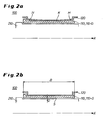
- FIGS. 2a and 2b show a second embodiment of the invention, according to which the bore in the bearing support body concave, that is, the bearing support body itself is convex.
- a concave configuration of the bore is recommended in particular when a lesser force is to be expected at the edges of the bearing support body than in its center or when the material of the bearing support body harder at its edges, that is, less yielding than at its center, that is, at half height of its width B.
- FIG. 2a shows the concave configuration of the bore in the bearing support body 120 in the unloaded state.
- the concave configuration is in the form of cavities H tapering conically towards the middle or half width B of the bearing support body 120.
- FIG. 2b shows FIG. 2b the bearing assembly according to the invention according to the second embodiment in a loaded state.
- the cavities H between the sliding body 110-G and the contour K of the bearing support body 120 have disappeared due to a deformation of the bearing support body 120 caused by the force.
- this deformation of this bearing support under load has no negative effect on the shape of the lubrication gap; compare FIG. 2b , This is advantageously maintained over the entire width B of the bearing support body with a uniform thickness distribution.
- the occurring load of the bearing assembly is optionally completely compensated by a suitable deformation of the bearing support body and the associated complementary deformation of the bore, which according to the invention has no negative impact on the shape of the lubrication gap S. Therefore, an unwanted local overload in the bearing is avoided by the inventive design of the bore in the unloaded bearing support body.
Landscapes
- Engineering & Computer Science (AREA)
- General Engineering & Computer Science (AREA)
- Mechanical Engineering (AREA)
- Rolling Contact Bearings (AREA)
- Rolls And Other Rotary Bodies (AREA)
Description
- Beim Walzen flacher und breiter Metallbänder oder auch beim Walzen von Metallprofilen treten zunehmend größere Walzkräfte auf, die von Lageranordnungen aufgenommen werden müssen. Im Stand der Technik bekannte Lageranordnungen 100 sind gemäß
Figur 3 und Figur 4 so aufgebaut, dass ein Lager 110, z. B. ein Gleitlager 110-G oder ein Wälzlager in einer ideal zylindrischen Bohrung eines sehr steif gestalteten Lagerstützkörpers 120, dass heißt eines so genannten Lagereinbaustücks aufgenommen wird. Die Arbeits- oder Stützwalzen 200 zum Walzen der besagten Metallbänder oder -Profile sind jeweils an ihren Enden mit ihren Zapfen 210 in solchen Lagern 110 unterstützt. In den Figuren 3 und 4 ist veranschaulicht, wie die Reactio R der Walzkräfte (vom Walzgut auf die Walze 200 wirkend) auf die beidseitigen Lageranordnungen aufgeteilt wird, um von diesen aufgefangen zu werden. - Ein Gleitlager in Form einer Lagerbuchse oder ein Außenring eines Wälzlagers, sind traditionell geometrisch zwar sehr genau hergestellt, jedoch wegen des nur begrenzt vorhandenen Bauraumes besitzen sie kaum eigene Steifigkeit. Sie benötigen daher eine gute Unterstützung, die über ihre Breite, das heißt in Richtung der Längsachse des Zapfens, möglichst gleich verteilt sein muss. Idealerweise würde eine solche gleichförmige Unterstützung durch einen über die Breite des Lagers gleichförmig steifen Lagerstützkörper bzw. ein gleichförmig steifes Einbaustück gewährleistet.
- Verschiedene Anforderungen an die Einbaustücke und/oder die Lagerungsart der Walzen verhindern jedoch in der Praxis eine gleichförmig steife Ausbildung der Lagerstützkörper bzw. der Einbaustücke über ihrer gesamten Breite. Deshalb sind in der Praxis die Lagerstützkörper mit in Richtung ihrer Längsachse lokal ausgeprägten Tragzonen ausgebildet, so dass sich die Lagerstützkörper - auch bei gleichförmiger Belastung - über die Breite des Lagersitzes sehr ungleichmäßig verformen. Eine ungleichförmige Verformung des Lagerstützkörpers kann auch bei einer gleichförmig steifen Ausbildung des Lagerstützkörpers eintreten, wenn die Belastung nicht gleichförmig, z.B. parabolisch verteilt ist.
- Eine ungleichmäßige Verformung wirkt sich in jedem Fall schädlich auf die Tragfähigkeit der Lageranordnung und somit auf deren Lebensdauer aus, da es zu unerwünschten Lastkonzentrationen, das heißt einzelnen Bereichen mit Überlast im Lager kommt.
- So ist in der Druckschrift
GB 1 380 947 - Ausgehend von dem zuvor beschriebenen Stand der Technik liegt der Erfindung die Aufgabe zugrunde, eine bekannte Lageranordnung, bei der das Auftreten von Bereichen mit lokaler Überlast über der Breite der Lageranordnung vermieden wird, dahingehend weiter zu bilden, dass die Fertigung des Lagerstützkörpers mit der Bohrung vereinfacht wird.
- Diese Aufgabe wird durch den Gegenstand des Anspruchs 1 gelöst. Demnach ist eine erfindungsgemäße Lageranordnung dadurch gekennzeichnet, dass die Bohrung in dem Lagerstützkörper in Form abschnittsweise aufeinander folgender - vorzugsweise gradlinig konturierter - konischer Bohrungen gefertigt ist.
- Die unter Last zu erwartende Verformungskurve des Lagerstützkörpers, d.h. insbesondere die unter Last zu erwartende Kontur der Bohrung des Lagerstützkörpers, lässt sich heute mit Finite-Elemente-Methoden FEM-Analysen sehr genau vorausberechnen. Sie ist abhängig von der Verteilung der auftretenden Belastung und der Verteilung der Steifigkeit des Lagerstützkörpers, z.B. jeweils in Richtung der Längsachse der Bohrung gesehen. Erfindungsgemäß wird deshalb vorgeschlagen, eine derart berechnete Verformungskurve ganz oder teilweise, zum Beispiel 50 - 90 % der Verformung unter voller Last, als negative, negierte bzw. komplementäre Kontur der Bohrung eines Lagerstützkörpers in unbelastetem Zustand zuzuordnen, um auf diese Weise die Verformung des Lagerstützkörpers unter Last zumindest teilweise kompensieren zu können. Die erfolgreiche Kompensation zeigt sich im Betrieb, das heißt unter Last, insbesondere dadurch, dass im Lager keine unerwünschten Stellen mit lokaler Überlast auftreten.
- Gemäß einem ersten Ausführungsbeispiel der Erfindung ist die Bohrung in dem unbelasteten Lagerstützkörper gegenüber ihrer eigenen Längsachse, welche identisch ist mit der Längsachse des Lagerstützkörpers, rotationssymmetrisch konvex ausgebildet. Diese konvexe Ausbildung der Bohrung, das heißt die konkave Ausbildung des Lagerstützkörpers auf seiner Innenseite, empfiehlt sich insbesondere dann, wenn an den Rändern des Lagerstützkörpers eine größere Krafteinwirkung von dem Walzenzapfen über das Lager auf den Lagerstützkörper erwartet wird, als in der Mitte des Lagerstützkörpers. Diese Kraftverteilung würde ein Anheben der Ränder des Lagerstützkörpers gegenüber dessen Mitte bewirken. Eine gleichartige Deformation des Lagerstützkörpers und damit der Bohrung könnte bei gleichförmiger Krafteinwirkung zum Beispiel auch dadurch entstehen, dass das Material des Lagerstützkörpers - über dessen Breite gesehen - an seinen Rändern weicher ist als in der Mitte.
- Alternativ kann die Bohrung in dem unbelasteten Lagerstützkörper gegenüber ihrer Längsachse auch rotationssymmetrisch konkav ausgebildet sein. Das heißt der Lagerstützkörper ist auf seiner Innenseite konvex ausgebildet. Eine konkave Ausbildung der Bohrung über seiner Breite empfiehlt sich dann, wenn auf Höhe der halben Breite des Lagerstützkörpers eine wesentlich größere radiale Krafteinwirkung von dem Walzenzapfen über das Lager auf den Lagerstützkörper zu erwarten ist, als an den Rändern der Bohrung bzw. des Lagerstützkörpers. Diese Kraftverteilung würde ein Anheben der Mitte des Lagerstützkörpers gegenüber dessen Rändern bewirken. Eine gleichartige Deformation des Lagerstützkörpers und damit der Bohrung könnte bei gleichförmiger Krafteinwirkung zum Beispiel auch dadurch entstehen, dass das Material des Lagerstützkörpers - über dessen Breite gesehen - in der Mitte weicher ist als an seinen Rändern.
- Das Lager kann zum Beispiel in Form eines Gleitlagers oder eines Wälzlagers ausgebildet sein.
- Bei Ausbildung des Lagers als Gleitlager in Form einer zylindrischen Lagerbuchse zeigt sich eine erfindungsgemäß erfolgreiche Kompensation der Verformung des Lagerstützkörpers im Betrieb, das heißt unter Last, vorteilhafterweise dadurch, dass im Übergangsbereich zwischen der Lagerbuchse und dem Walzenzapfen - möglichst über die gesamte Tiefe/Breite der Bohrung - ein Schmierspalt mit einer gleichförmigen Dicke ausgebildet ist.
- Bei Ausbildung des Lagers als Wälzlager umfasst das Lager einen Außenring, welcher von der Bohrung in dem Lagerstützkörper aufgenommen ist, einen Innenring, welcher auf dem Walzenzapfen oder der Zapfenbuchse sitzt, und Wälzkörper zwischen dem Außenring und dem Innenring. Eine erfindungsgemäß erfolgreiche Kompensation der Verformung des Lagerstützkörpers zeigt sich im Betrieb, das heißt unter Last, vorteilhafterweise dadurch, dass sich der Innenring und der Außenring als Funktionsflächen über ihrer gesamten Breite bzw. über der gesamten Breite der Bohrung in dem Lagerstützkörper gleichförmig koaxial bzw. parallel gegenüber stehen. Es gibt dann keine unerwünschte lokale Überlast.
- Der Lagerstützkörper repräsentiert typischerweise das Gehäuse für das Lager in Form eines Lagereinbaustücks. Er verbindet typischerweise die Walze mit dem Walzgerüst.
- Die Erfindung betrifft Lageranordnungen für beidseitig gelagerte Walzen mit einem Längen/Durchmesser-Verhältnis (UD-Verhältnis) von 65 - 100 %.
- Der Beschreibung sind vier Figuren beigefügt, wobei
- Figur 1a
- eine erfindungsgemäße Lageranordnung gemäß einem ersten Ausführungsbeispiel mit konvexer Bohrung im Lagerstützkörper in unbelastetem Zustand;
- Figur 1b
- die Lageranordnung nach
Figur 1 a in belastetem Zustand; - Figur 2a
- eine erfindungsgemäße Lageranordnung gemäß einem zweiten Ausführungsbeispiel mit konkaver Bohrung in dem Lagerstützkörper in unbelastetem Zustand;
- Figur 2b
- die Lageranordnung nach
Figur 2a in belastetem Zustand; - Figur 3
- eine Walze mit beidseitiger Lagerung (Stand der Technik); und
- Figur 4
- eine Detailansicht von
Figur 3 betreffend die Lageranordnung (Stand der Technik) - Die Erfindung wird nachfolgend unter Bezugnahme auf die genannten Figuren detailliert beschrieben. In allen Figuren sind gleiche technische Merkmale mit gleichen Bezugszeichen bezeichnet.
-
Figur 1 a zeigt ein erstes Ausführungsbeispiel für die erfindungsgemäße Lageranordnung mit einer konvexen Kontur K der Bohrung in dem Lagerstützkörper 120 in unbelastetem Zustand. Anders ausgedrückt: der Lagerstützkörper ist konkav ausgebildet. Das Lager ist bei dem inFigur 1 a gezeigten ersten Ausführungsbeispiel in Form eines Gleitlagers ausgebildet, wobei das Bezugzeichen 110-G den Gleitkörper in Form einer Lagerbuchse zwischen dem Stützkörper 120 und dem Zapfen 210 - bzw. einer Zapfenbuchse 210 bei konischem Zapfen einer gelagerten Walze, zeigt. Die konvexe Ausbildung der Bohrung in dem Lagerstützkörper zeigt sich inFigur 1a durch den gewölbten Hohlraum H zwischen dem unbelasteten Lagerstützkörper 120 und dem Gleitkörper 110-G. -
Figur 1b zeigt die Lageranordnung ausFigur 1 a in belastetem Zustand. Die Belastung erfolgt typischerweise durch eine radiale Krafteinwirkung von dem Walzenzapfen über das Lager auf den Lagerstützkörper. Die in dem ersten Ausführungsbeispiel gezeigte konvexe Ausbildung der Bohrung in dem Lagerstützkörper empfiehlt sich insbesondere dann, wenn im Bereich der halben Breite B des Lagerstützkörpers mit einer geringeren radialen Krafteinwirkung zu rechnen ist als an dessen Rändern. Die konvexere Ausbildung der Bohrung empfiehlt sich auch dann, wenn das Material an den Rändern des Lagerstützkörpers weicher, das heißt weniger steif ausgebildet ist, als im Bereich der Mitte der Breite. - Wie in
Figur 1b zu erkennen ist, ist der gewölbte Hohlraum zwischen dem Lagerstützkörper 120 und dem Lagergleitkörper 110-G nunmehr unter Last verschwunden. Vorteilhafterweise hat die besagte Deformation des Lagerstützkörpers unter Last - wie inFigur 1b gezeigt - keine negative Auswirkung auf die Gestalt des Schmierspaltes S, insbesondere nicht zu einer lokalen Verengung des Schmierspaltes im Bereich der halben Breite B des Lagerstützkörpers geführt. Dieser ist auch unter Last zylinderförmig ausgebildet mit gleichmäßiger Dickenverteilung D über der gesamten Breite B des Lagerstützkörpers. - Die
Figuren 2a und 2b zeigen ein zweites Ausführungsbeispiel der Erfindung, wonach die Bohrung in dem Lagerstützkörper konkav, das heißt der Lagerstützkörper selber konvex ausgebildet ist. Eine derartige konkave Ausgestaltung der Bohrung empfiehlt sich insbesondere dann, wenn an den Rändern des Lagerstützkörpers eine geringere Krafteinwirkung zu erwarten ist als in dessen Mitte oder wenn das Material des Lagerstützkörpers an dessen Rändern härter, das heißt weniger nachgiebig ist als in seiner Mitte, das heißt auf halber Höhe seiner Breite B. -
Figur 2a zeigt die konkave Ausbildung der Bohrung in dem Lagerstützkörper 120 in unbelastetem Zustand. Die konkave Ausbildung zeigt sich in Form von konisch auf die Mitte bzw. halbe Breite B des Lagerstützkörpers 120 zulaufenden Hohlräumen H. - Anders als
Figur 2a zeigtFigur 2b die erfindungsgemäße Lageranordnung gemäß dem zweiten Ausführungsbeispiel in belastetem Zustand. Die Hohlräume H zwischen dem Gleitkörper 110-G und der Kontur K des Lagerstützkörpers 120 sind verschwunden aufgrund einer durch die Krafteinwirkung bedingten Deformation des Lagerstützkörpers 120. Vorteilhafterweise hat diese Deformation dieses Lagerstützkörpers unter Last keine negative Auswirkung auf die Gestalt des Schmierspalts; vergleicheFigur 2b . Dieser bleibt vorteilhafterweise über der gesamten Breite B des Lagerstützkörpers mit gleichmäßiger Dickenverteilung erhalten. - Für beide Ausführungsbeispiele gemäß den
Figuren 1 und2 gilt: Die auftretende Belastung der Lageranordnung wird gegebenenfalls vollständig durch eine geeignete Deformation des Lagerstützkörpers und die damit einhergehende komplementäre Deformation der Bohrung kompensiert, welche erfindungsgemäß keine negativen Auswirkungen auf die Form des Schmierspaltes S hat. Deshalb wird durch die erfindungsgemäße Ausbildung der Bohrung in dem unbelasteten Lagerstützkörper eine unerwünschte lokale Überlast in dem Lager vermieden.
Claims (6)
- Lageranordnung (100), welche aufweist:ein Lager (110) zum drehbaren Lagern des Zapfens (210) einer Walze (200) in einem Walzgerüst; undeinen Lagerstützkörper (120) mit einer Bohrung zur Aufnahme des Lagers,wobei die Kontur (K) der Bohrung in dem unbelasteten Lagerstützkörper zumindest näherungsweise entsprechend der negierten Kontur der Bohrung bei einer vorausberechneten Belastung des Lagerstützkörpers ausgebildet ist,dadurch gekennzeichnet,dass die Bohrung in dem Lagerstützkörper (120) in Form abschnittsweise aufeinander folgender- vorzugsweise gradlinig konturierter- konischer Bohrungen gefertigt ist
- Lageranordnung (100) nach Anspruch 1,
dadurch gekennzeichnet,
dass die Bohrung in dem unbelasteten Lagerstützkörper rotationssymmetrisch konvex ausgebildet ist. - Lageranordnung (100) nach Anspruch 1,
dadurch gekennzeichnet,
dass die Bohrung in dem unbelasteten Lagerstützkörper rotationssymmetrisch konkav ausgebildet ist. - Lageranordnung (100) nach einem der vorangegangenen Ansprüche,
dadurch gekennzeichnet,
dass das Lager (110) als Gleitlager (110-G) in Form einer Lagerbuchse zum drehbaren Lagern des Zapfens (210) der Walze (200) ausgebildet ist, wobei zwischen der Lagerbuchse und dem Zapfen der Walze ein zylinderförmiger Schmierspalt (S) ausgebildet ist. - Lageranordnung (100) nach einem der Ansprüche 1 bis 4,
dadurch gekennzeichnet,
dass das Lager (110) in Form eines Wälzlagers zum drehbaren Lagern des Zapfens (210) der Walze ausgebildet ist. - Lageranordnung (100) nach einem der vorangegangenen Ansprüche,
dadurch gekennzeichnet,
dass der Lagerstützkörper (120) das Gehäuse für das Lager in Form eines Lagereinbaustücks repräsentiert, welches mit dem Walzgerüst verbunden ist
Applications Claiming Priority (2)
| Application Number | Priority Date | Filing Date | Title |
|---|---|---|---|
| DE102008004113 | 2008-01-11 | ||
| PCT/EP2009/000115 WO2009087114A1 (de) | 2008-01-11 | 2009-01-12 | Lageranordnung |
Publications (2)
| Publication Number | Publication Date |
|---|---|
| EP2232090A1 EP2232090A1 (de) | 2010-09-29 |
| EP2232090B1 true EP2232090B1 (de) | 2012-11-28 |
Family
ID=40394497
Family Applications (1)
| Application Number | Title | Priority Date | Filing Date |
|---|---|---|---|
| EP09700621A Not-in-force EP2232090B1 (de) | 2008-01-11 | 2009-01-12 | Lageranordnung |
Country Status (3)
| Country | Link |
|---|---|
| US (1) | US8246250B2 (de) |
| EP (1) | EP2232090B1 (de) |
| WO (1) | WO2009087114A1 (de) |
Families Citing this family (6)
| Publication number | Priority date | Publication date | Assignee | Title |
|---|---|---|---|---|
| DE102010047471A1 (de) * | 2010-10-06 | 2012-04-12 | Sms Siemag Ag | Verfahren zum Aufbereiten einer Lageranordnung und Lageranordnung |
| DE102012209828A1 (de) * | 2012-06-12 | 2013-12-12 | Sms Siemag Ag | Walzenanordnung |
| DE102012209831A1 (de) * | 2012-06-12 | 2013-12-12 | Sms Siemag Ag | Walzenanordnung |
| WO2014056419A1 (zh) * | 2012-10-08 | 2014-04-17 | 上海泛华紧固系统有限公司 | 一种用于滚压管螺纹的滚压头、及其设备和应用该设备加工的管圆柱毛坯 |
| RU2667570C2 (ru) * | 2013-08-27 | 2018-09-21 | Ниссан Мотор Ко., Лтд. | Многозвенный поршневой кривошипно-шатунный механизм для двигателя внутреннего сгорания |
| DE102015209637A1 (de) * | 2015-05-26 | 2016-12-01 | Sms Group Gmbh | Walzenanordnung |
Family Cites Families (9)
| Publication number | Priority date | Publication date | Assignee | Title |
|---|---|---|---|---|
| DE2223721A1 (de) | 1971-11-29 | 1973-06-07 | Thaelmann Schwermaschbau Veb | Einstellbare gleitlagerung |
| US3995920A (en) * | 1973-08-06 | 1976-12-07 | Bucha Louis J | Roller bearing |
| JPS56113821A (en) * | 1980-02-08 | 1981-09-08 | Hitachi Ltd | Roll neck bearing |
| US6149309A (en) * | 1999-07-13 | 2000-11-21 | Morgan Construction Company | Bushing for oil film bearing |
| TWI271225B (en) * | 2002-05-29 | 2007-01-21 | Sms Demag Ag | Apparatus for controlled influencing of the supporting forces of backing rollers |
| DE10316316A1 (de) * | 2003-04-10 | 2004-10-21 | Sms Demag Ag | Vorrichtung zur Rückführung von Öl in Walzenlagern |
| DE10336894A1 (de) * | 2003-08-08 | 2005-03-10 | Sms Demag Ag | Ölfilmlager für Walzenzapfen mit hydrostatischer Unterstützung |
| US7374257B2 (en) * | 2005-02-11 | 2008-05-20 | Caterpillar Inc. | Machine track roller assembly |
| US20110075956A1 (en) * | 2009-09-28 | 2011-03-31 | Morgan Construction Company | Sleeve for Oil Film Bearing |
-
2009
- 2009-01-12 EP EP09700621A patent/EP2232090B1/de not_active Not-in-force
- 2009-01-12 WO PCT/EP2009/000115 patent/WO2009087114A1/de not_active Ceased
- 2009-01-12 US US12/735,257 patent/US8246250B2/en not_active Expired - Fee Related
Also Published As
| Publication number | Publication date |
|---|---|
| US20100284639A1 (en) | 2010-11-11 |
| EP2232090A1 (de) | 2010-09-29 |
| US8246250B2 (en) | 2012-08-21 |
| WO2009087114A1 (de) | 2009-07-16 |
Similar Documents
| Publication | Publication Date | Title |
|---|---|---|
| DE60118695T2 (de) | Hülse für Ölfilmlager eines Walzwerkes | |
| DE2702321C2 (de) | Lagerung eines auf einem Bolzen o.dgl. rotierenden Maschinenteils | |
| WO2018189143A1 (de) | Lageranordnung zur lagerung eines rotorblatts einer windenergieanlage | |
| EP2232090A1 (de) | Lageranordnung | |
| DE60120637T2 (de) | Planetenradsatz | |
| DE2154836A1 (de) | Ring-Tonnenlager | |
| DE4232433C2 (de) | Käfigführung für Wälzlager, insbesondere für Axial-Zylinderrollenlager | |
| DE3027263C2 (de) | Lagerung von Zapfen in Gabelaugen von Kreuzgelenken mittels eines Zylinderrollenlagers | |
| DE2231839C2 (de) | Hydrodynamisches kombiniertes Axial- und Radiallager für rasch umlaufende Wellen | |
| EP2379902B1 (de) | Walze und ein walzgerüst zum walzen von walzgut | |
| WO2013186141A1 (de) | Walzenanordnung | |
| EP1880123A1 (de) | Vierreihiges kegelrollenlager | |
| EP2858768B1 (de) | Walzenanordnung | |
| WO2009059585A2 (de) | Lagerung eines planetenrades zur optimierung der lastverteilung | |
| EP3684523B1 (de) | Walzgerüst | |
| DE102011078713B4 (de) | Radlageranordnung | |
| DE102019135078A1 (de) | Wälzlagerring und Verfahren zur Bearbeitung eines Wälzlagerrings | |
| DE102007062482B4 (de) | Verwendung einer Zylinderrollenlagerung | |
| DE102008006626A1 (de) | Zapfendichtung für Walzenlager | |
| DE3325170A1 (de) | Lager | |
| DE102008047453B4 (de) | Anlaufscheibe, Lagereinheit und Achsschenkelbolzenlagerung | |
| EP4069988B1 (de) | Verfahren zur erhöhung der tragfähigkeit und walzvorrichtung zum hartwalzen einer randschichtgehärteten wälzlagerlaufbahn | |
| DE501139C (de) | Anordnung von Lagern zur Aufnahme von Radial- wie Axialdruck | |
| DE102021205276A1 (de) | Zapfenbuchse als Teil eines Ölfilmlagers | |
| AT223439B (de) | Elastische Bettung für Wälztraglager |
Legal Events
| Date | Code | Title | Description |
|---|---|---|---|
| PUAI | Public reference made under article 153(3) epc to a published international application that has entered the european phase |
Free format text: ORIGINAL CODE: 0009012 |
|
| 17P | Request for examination filed |
Effective date: 20100811 |
|
| AK | Designated contracting states |
Kind code of ref document: A1 Designated state(s): AT BE BG CH CY CZ DE DK EE ES FI FR GB GR HR HU IE IS IT LI LT LU LV MC MK MT NL NO PL PT RO SE SI SK TR |
|
| AX | Request for extension of the european patent |
Extension state: AL BA RS |
|
| DAX | Request for extension of the european patent (deleted) | ||
| GRAP | Despatch of communication of intention to grant a patent |
Free format text: ORIGINAL CODE: EPIDOSNIGR1 |
|
| GRAC | Information related to communication of intention to grant a patent modified |
Free format text: ORIGINAL CODE: EPIDOSCIGR1 |
|
| GRAS | Grant fee paid |
Free format text: ORIGINAL CODE: EPIDOSNIGR3 |
|
| GRAA | (expected) grant |
Free format text: ORIGINAL CODE: 0009210 |
|
| AK | Designated contracting states |
Kind code of ref document: B1 Designated state(s): AT BE BG CH CY CZ DE DK EE ES FI FR GB GR HR HU IE IS IT LI LT LU LV MC MK MT NL NO PL PT RO SE SI SK TR |
|
| REG | Reference to a national code |
Ref country code: GB Ref legal event code: FG4D Free format text: NOT ENGLISH |
|
| REG | Reference to a national code |
Ref country code: CH Ref legal event code: EP |
|
| REG | Reference to a national code |
Ref country code: AT Ref legal event code: REF Ref document number: 586339 Country of ref document: AT Kind code of ref document: T Effective date: 20121215 |
|
| REG | Reference to a national code |
Ref country code: IE Ref legal event code: FG4D Free format text: LANGUAGE OF EP DOCUMENT: GERMAN |
|
| REG | Reference to a national code |
Ref country code: DE Ref legal event code: R096 Ref document number: 502009005501 Country of ref document: DE Effective date: 20130124 |
|
| REG | Reference to a national code |
Ref country code: NL Ref legal event code: VDEP Effective date: 20121128 |
|
| REG | Reference to a national code |
Ref country code: LT Ref legal event code: MG4D |
|
| PG25 | Lapsed in a contracting state [announced via postgrant information from national office to epo] |
Ref country code: ES Free format text: LAPSE BECAUSE OF FAILURE TO SUBMIT A TRANSLATION OF THE DESCRIPTION OR TO PAY THE FEE WITHIN THE PRESCRIBED TIME-LIMIT Effective date: 20130311 Ref country code: FI Free format text: LAPSE BECAUSE OF FAILURE TO SUBMIT A TRANSLATION OF THE DESCRIPTION OR TO PAY THE FEE WITHIN THE PRESCRIBED TIME-LIMIT Effective date: 20121128 Ref country code: LT Free format text: LAPSE BECAUSE OF FAILURE TO SUBMIT A TRANSLATION OF THE DESCRIPTION OR TO PAY THE FEE WITHIN THE PRESCRIBED TIME-LIMIT Effective date: 20121128 Ref country code: SE Free format text: LAPSE BECAUSE OF FAILURE TO SUBMIT A TRANSLATION OF THE DESCRIPTION OR TO PAY THE FEE WITHIN THE PRESCRIBED TIME-LIMIT Effective date: 20121128 Ref country code: NO Free format text: LAPSE BECAUSE OF FAILURE TO SUBMIT A TRANSLATION OF THE DESCRIPTION OR TO PAY THE FEE WITHIN THE PRESCRIBED TIME-LIMIT Effective date: 20130228 |
|
| PG25 | Lapsed in a contracting state [announced via postgrant information from national office to epo] |
Ref country code: LV Free format text: LAPSE BECAUSE OF FAILURE TO SUBMIT A TRANSLATION OF THE DESCRIPTION OR TO PAY THE FEE WITHIN THE PRESCRIBED TIME-LIMIT Effective date: 20121128 Ref country code: PT Free format text: LAPSE BECAUSE OF FAILURE TO SUBMIT A TRANSLATION OF THE DESCRIPTION OR TO PAY THE FEE WITHIN THE PRESCRIBED TIME-LIMIT Effective date: 20130328 Ref country code: GR Free format text: LAPSE BECAUSE OF FAILURE TO SUBMIT A TRANSLATION OF THE DESCRIPTION OR TO PAY THE FEE WITHIN THE PRESCRIBED TIME-LIMIT Effective date: 20130301 Ref country code: PL Free format text: LAPSE BECAUSE OF FAILURE TO SUBMIT A TRANSLATION OF THE DESCRIPTION OR TO PAY THE FEE WITHIN THE PRESCRIBED TIME-LIMIT Effective date: 20121128 Ref country code: SI Free format text: LAPSE BECAUSE OF FAILURE TO SUBMIT A TRANSLATION OF THE DESCRIPTION OR TO PAY THE FEE WITHIN THE PRESCRIBED TIME-LIMIT Effective date: 20121128 |
|
| BERE | Be: lapsed |
Owner name: SMS SIEMAG AG Effective date: 20130131 |
|
| PG25 | Lapsed in a contracting state [announced via postgrant information from national office to epo] |
Ref country code: CZ Free format text: LAPSE BECAUSE OF FAILURE TO SUBMIT A TRANSLATION OF THE DESCRIPTION OR TO PAY THE FEE WITHIN THE PRESCRIBED TIME-LIMIT Effective date: 20121128 Ref country code: EE Free format text: LAPSE BECAUSE OF FAILURE TO SUBMIT A TRANSLATION OF THE DESCRIPTION OR TO PAY THE FEE WITHIN THE PRESCRIBED TIME-LIMIT Effective date: 20121128 Ref country code: BG Free format text: LAPSE BECAUSE OF FAILURE TO SUBMIT A TRANSLATION OF THE DESCRIPTION OR TO PAY THE FEE WITHIN THE PRESCRIBED TIME-LIMIT Effective date: 20130228 Ref country code: SK Free format text: LAPSE BECAUSE OF FAILURE TO SUBMIT A TRANSLATION OF THE DESCRIPTION OR TO PAY THE FEE WITHIN THE PRESCRIBED TIME-LIMIT Effective date: 20121128 Ref country code: DK Free format text: LAPSE BECAUSE OF FAILURE TO SUBMIT A TRANSLATION OF THE DESCRIPTION OR TO PAY THE FEE WITHIN THE PRESCRIBED TIME-LIMIT Effective date: 20121128 |
|
| PG25 | Lapsed in a contracting state [announced via postgrant information from national office to epo] |
Ref country code: MC Free format text: LAPSE BECAUSE OF NON-PAYMENT OF DUE FEES Effective date: 20130131 Ref country code: NL Free format text: LAPSE BECAUSE OF FAILURE TO SUBMIT A TRANSLATION OF THE DESCRIPTION OR TO PAY THE FEE WITHIN THE PRESCRIBED TIME-LIMIT Effective date: 20121128 Ref country code: RO Free format text: LAPSE BECAUSE OF FAILURE TO SUBMIT A TRANSLATION OF THE DESCRIPTION OR TO PAY THE FEE WITHIN THE PRESCRIBED TIME-LIMIT Effective date: 20121128 Ref country code: IT Free format text: LAPSE BECAUSE OF FAILURE TO SUBMIT A TRANSLATION OF THE DESCRIPTION OR TO PAY THE FEE WITHIN THE PRESCRIBED TIME-LIMIT Effective date: 20121128 |
|
| REG | Reference to a national code |
Ref country code: CH Ref legal event code: PL |
|
| PLBE | No opposition filed within time limit |
Free format text: ORIGINAL CODE: 0009261 |
|
| STAA | Information on the status of an ep patent application or granted ep patent |
Free format text: STATUS: NO OPPOSITION FILED WITHIN TIME LIMIT |
|
| GBPC | Gb: european patent ceased through non-payment of renewal fee |
Effective date: 20130228 |
|
| REG | Reference to a national code |
Ref country code: IE Ref legal event code: MM4A |
|
| REG | Reference to a national code |
Ref country code: FR Ref legal event code: ST Effective date: 20130930 |
|
| PG25 | Lapsed in a contracting state [announced via postgrant information from national office to epo] |
Ref country code: CH Free format text: LAPSE BECAUSE OF NON-PAYMENT OF DUE FEES Effective date: 20130131 Ref country code: LI Free format text: LAPSE BECAUSE OF NON-PAYMENT OF DUE FEES Effective date: 20130131 Ref country code: BE Free format text: LAPSE BECAUSE OF NON-PAYMENT OF DUE FEES Effective date: 20130131 |
|
| 26N | No opposition filed |
Effective date: 20130829 |
|
| PG25 | Lapsed in a contracting state [announced via postgrant information from national office to epo] |
Ref country code: HR Free format text: LAPSE BECAUSE OF FAILURE TO SUBMIT A TRANSLATION OF THE DESCRIPTION OR TO PAY THE FEE WITHIN THE PRESCRIBED TIME-LIMIT Effective date: 20121128 Ref country code: FR Free format text: LAPSE BECAUSE OF NON-PAYMENT OF DUE FEES Effective date: 20130131 Ref country code: CY Free format text: LAPSE BECAUSE OF FAILURE TO SUBMIT A TRANSLATION OF THE DESCRIPTION OR TO PAY THE FEE WITHIN THE PRESCRIBED TIME-LIMIT Effective date: 20121128 |
|
| REG | Reference to a national code |
Ref country code: DE Ref legal event code: R097 Ref document number: 502009005501 Country of ref document: DE Effective date: 20130829 |
|
| PG25 | Lapsed in a contracting state [announced via postgrant information from national office to epo] |
Ref country code: IE Free format text: LAPSE BECAUSE OF NON-PAYMENT OF DUE FEES Effective date: 20130112 Ref country code: GB Free format text: LAPSE BECAUSE OF NON-PAYMENT OF DUE FEES Effective date: 20130228 |
|
| PG25 | Lapsed in a contracting state [announced via postgrant information from national office to epo] |
Ref country code: MT Free format text: LAPSE BECAUSE OF FAILURE TO SUBMIT A TRANSLATION OF THE DESCRIPTION OR TO PAY THE FEE WITHIN THE PRESCRIBED TIME-LIMIT Effective date: 20121128 |
|
| REG | Reference to a national code |
Ref country code: AT Ref legal event code: MM01 Ref document number: 586339 Country of ref document: AT Kind code of ref document: T Effective date: 20140112 |
|
| PG25 | Lapsed in a contracting state [announced via postgrant information from national office to epo] |
Ref country code: AT Free format text: LAPSE BECAUSE OF NON-PAYMENT OF DUE FEES Effective date: 20140112 |
|
| PG25 | Lapsed in a contracting state [announced via postgrant information from national office to epo] |
Ref country code: TR Free format text: LAPSE BECAUSE OF FAILURE TO SUBMIT A TRANSLATION OF THE DESCRIPTION OR TO PAY THE FEE WITHIN THE PRESCRIBED TIME-LIMIT Effective date: 20121128 |
|
| PG25 | Lapsed in a contracting state [announced via postgrant information from national office to epo] |
Ref country code: LU Free format text: LAPSE BECAUSE OF NON-PAYMENT OF DUE FEES Effective date: 20130112 Ref country code: HU Free format text: LAPSE BECAUSE OF FAILURE TO SUBMIT A TRANSLATION OF THE DESCRIPTION OR TO PAY THE FEE WITHIN THE PRESCRIBED TIME-LIMIT; INVALID AB INITIO Effective date: 20090112 Ref country code: MK Free format text: LAPSE BECAUSE OF FAILURE TO SUBMIT A TRANSLATION OF THE DESCRIPTION OR TO PAY THE FEE WITHIN THE PRESCRIBED TIME-LIMIT Effective date: 20121128 |
|
| REG | Reference to a national code |
Ref country code: DE Ref legal event code: R082 Ref document number: 502009005501 Country of ref document: DE Representative=s name: HEMMERICH & KOLLEGEN, DE Ref country code: DE Ref legal event code: R081 Ref document number: 502009005501 Country of ref document: DE Owner name: SMS GROUP GMBH, DE Free format text: FORMER OWNER: SMS SIEMAG AG, 40237 DUESSELDORF, DE |
|
| PG25 | Lapsed in a contracting state [announced via postgrant information from national office to epo] |
Ref country code: IS Free format text: LAPSE BECAUSE OF FAILURE TO SUBMIT A TRANSLATION OF THE DESCRIPTION OR TO PAY THE FEE WITHIN THE PRESCRIBED TIME-LIMIT Effective date: 20121128 |
|
| PGFP | Annual fee paid to national office [announced via postgrant information from national office to epo] |
Ref country code: DE Payment date: 20170120 Year of fee payment: 9 |
|
| REG | Reference to a national code |
Ref country code: DE Ref legal event code: R119 Ref document number: 502009005501 Country of ref document: DE |
|
| PG25 | Lapsed in a contracting state [announced via postgrant information from national office to epo] |
Ref country code: DE Free format text: LAPSE BECAUSE OF NON-PAYMENT OF DUE FEES Effective date: 20180801 |