EP2232094B1 - Dämpfungseinstellbarer stossdämpfer mit doppelfrontversiegelter vorrichtung zur verbindung zwischen einem zwischenrohr und einem steuerventil - Google Patents
Dämpfungseinstellbarer stossdämpfer mit doppelfrontversiegelter vorrichtung zur verbindung zwischen einem zwischenrohr und einem steuerventil Download PDFInfo
- Publication number
- EP2232094B1 EP2232094B1 EP08865805A EP08865805A EP2232094B1 EP 2232094 B1 EP2232094 B1 EP 2232094B1 EP 08865805 A EP08865805 A EP 08865805A EP 08865805 A EP08865805 A EP 08865805A EP 2232094 B1 EP2232094 B1 EP 2232094B1
- Authority
- EP
- European Patent Office
- Prior art keywords
- control valve
- intermediate tube
- shock
- tube
- spacer body
- Prior art date
- Legal status (The legal status is an assumption and is not a legal conclusion. Google has not performed a legal analysis and makes no representation as to the accuracy of the status listed.)
- Active
Links
Images

Classifications
-
- F—MECHANICAL ENGINEERING; LIGHTING; HEATING; WEAPONS; BLASTING
- F16—ENGINEERING ELEMENTS AND UNITS; GENERAL MEASURES FOR PRODUCING AND MAINTAINING EFFECTIVE FUNCTIONING OF MACHINES OR INSTALLATIONS; THERMAL INSULATION IN GENERAL
- F16F—SPRINGS; SHOCK-ABSORBERS; MEANS FOR DAMPING VIBRATION
- F16F9/00—Springs, vibration-dampers, shock-absorbers, or similarly-constructed movement-dampers using a fluid or the equivalent as damping medium
- F16F9/32—Details
- F16F9/36—Special sealings, including sealings or guides for piston-rods
- F16F9/369—Sealings for elements other than pistons or piston rods, e.g. valves
-
- F—MECHANICAL ENGINEERING; LIGHTING; HEATING; WEAPONS; BLASTING
- F16—ENGINEERING ELEMENTS AND UNITS; GENERAL MEASURES FOR PRODUCING AND MAINTAINING EFFECTIVE FUNCTIONING OF MACHINES OR INSTALLATIONS; THERMAL INSULATION IN GENERAL
- F16F—SPRINGS; SHOCK-ABSORBERS; MEANS FOR DAMPING VIBRATION
- F16F9/00—Springs, vibration-dampers, shock-absorbers, or similarly-constructed movement-dampers using a fluid or the equivalent as damping medium
- F16F9/32—Details
- F16F9/3207—Constructional features
- F16F9/3235—Constructional features of cylinders
- F16F9/325—Constructional features of cylinders for attachment of valve units
Definitions
- the present invention relates in general to a damping-adjustable shock-absorber intended to be used for instance in an active or semi-active suspension system of a motor vehicle, and more in particular to a sealed connection device between an intermediate tube and a control valve of the shock-absorber.
- a typical damping-adjustable shock-absorber comprises:
- a further sealed connection arrangement between the intermediate tube and the control valve of a damping-adjustable shock-absorber is known from Us Patent US6035979 .
- the intermediate tube has a connection opening in which a fitting collar for the control valve is secured by caulking.
- An O-ring ensuring a sealed connection between the valve and the intermediate tube is radially (wherein the terms "radial” and “axial” are to be intended, in the following description and claims, as referred to the axis of the control valve, that is to say, to an axis extending perpendicularly to the axis of the shock-absorber) interposed between the fitting collar and an attachment portion of the control valve.
- connection between the intermediate tube and the control valve involves a single radial sealing member consisting in both cases in an O-ring.
- the invention is based on the idea of providing a sealed connection device between the intermediate tube and the control valve comprising:
- a damping adjustable shock-absorber according to the invention is capable of ensuring a correct oil flow, and accordingly a correct pressure transmission, between the intermediate tube and the control valve. Moreover, a damping-adjustable shock-absorber according to the invention has a more compact structure, is easier to assemble and has a lower manufacturing cost than the prior art discussed above.
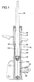
- a damping-adjustable shock-absorber intended to be used in particular in an active or semi-active suspension system for a motor vehicle is generally indicated 10 and comprises, in per-se-known manner:
- the control valve 28 is secured to the outer tube 20 so as to extend substantially perpendicularly to the axis of the outer tube, that is to say, perpendicularly to the axis of the shock-absorber.
- the valve 28 is threaded into an internally threaded tubular attachment element 30 which is in turn rigidly connected, for instance by welding, to the outer tube 20.
- control valve 28 has an inlet 32 in fluid communication with the by-pass chamber 22 through an opening 34 formed in the intermediate tube 22.
- a sealed connection device 36 is axially interposed between the intermediate tube 22 and the control valve 28 at the opening 34 to allow the damping fluid to flow without leakage from the by-pass chamber 24 to the inlet 32 of the control valve 28 and vice versa.
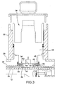
- the sealed connection device 36 is configured so as to form a double front seal, on the one hand with the intermediate tube 22 and on the other hand with a valve body 38 of the control valve 28.
- the sealed connection device 36 comprises a spacer body 40 forming a radially inner tubular portion 42 which at a first end (upper end, when seen by the observer of Figure 2 ) is in abutment against a front face 44 of the valve body 38 and at the opposite end (lower end, when seen form the observer of Figure 2 ) projects into the by-pass chamber 24 of the intermediate tube 22 through the opening 34, and a radial flange portion 46 which extends radially from the tubular portion 42 and is in abutment at its opposite axial ends against the front face 44 of the valve body 38 and against the outer cylindrical surface of the intermediate tube 22.
- the sealed connection device 36 further comprises a first front sealing member 48, which is formed in this case as an O-ring and is received in a first toroidal groove 50 provided on a first axial face 52 (upper face, when seen by the observer of Figure 2 ) of the flange portion 46 of the spacer body 40 so as to seal against the front face 44 of the valve body 38, and a second front sealing member 54, which is formed in this case as an O-ring as well and is received in a second toroidal groove 56 provided on a second axial face 58 (lower face, when seen by the observer of Figure 2 ) of the flange portion 46 of the spacer body 40 so as to seal against the outer cylindrical surface of the intermediate tube 22.
- the spacer body 40 is formed as a single piece of metal, while the two O-rings 48 and 54 are made of elastomeric material.
- the sealed connection device 36 of Figure 3 comprises a spacer body 40, a first front sealing member 48 in contact with the front face 44 of the valve body 38 and a second front sealing member 54 in contact with the outer cylindrical surface of the intermediate tube 22.
- the spacer body 40 is made of elastomeric material, internally reinforced by a metal core 60, and forms integrally the two front sealing members 48 and 54.
- first front sealing member 48 is formed on a first axial face 52 (upper face, when seen by the observer of Figure 3 ) of the spacer body 40, while the second front sealing member 54 is formed on an opposite axial face 58 (lower face, when seen by the observer of Figure 3 ).
- the spacer body 40 also forms a radially inner tubular portion 42 which projects partially into the by-pass chamber 24 of the intermediate tube 22 through the opening 34.
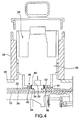
- FIG. 4 A further variant of embodiment of the sealed connection device according to the invention is illustrated in Figure 4 , where parts and elements identical or corresponding to those of Figures 2 and 3 have been given the same reference numerals.
- the spacer body 40 is simply a ring arranged around the opening 34 of the intermediate tube 22 in contact with a first axial face 52 thereof against the front face 44 of the valve body 38 and with an opposite axial face 58 thereof against the outer cylindrical surface of the intermediate tube itself.
- the first and second front sealing members 48 and 54 are formed in this case by a single piece of elastomeric material of annular shape which is secured to the inner cylindrical surface of the spacer body 40.
Landscapes
- Engineering & Computer Science (AREA)
- General Engineering & Computer Science (AREA)
- Mechanical Engineering (AREA)
- Fluid-Damping Devices (AREA)
- Axle Suspensions And Sidecars For Cycles (AREA)
Claims (8)
- Dämpfungseinstellbarer Stoßdämpfer (10) mit einem Druckrohr (12), einem Außenrohr (20), einem auf dem Druckrohr (12) befestigten Zwischenrohr, einem Steuerventil (28) zum Steuern des Stroms eines Dämpfungsmediums zu/aus dem Zwischenrohr (22) und einer versiegelten Verbindungsvorrichtung (36) für die versiegelte Verbindung des Steuerventils (28) mit dem Zwischenrohr (22),
dadurch gekennzeichnet, dass die versiegelte Verbindungsvorrichtung (36) einen axial zwischen das Zwischenrohr (22) und das Steuerventil (28) geschalteten Abstandskörper (40), ein erstes frontversiegelndes Element (48) im Kontakt mit einer vorderen Fläche (44) des Steuerventils (28) und ein zweites frontversiegelndes Element (54) im Kontakt mit der äußeren zylindrischen Oberfläche des Zwischenrohrs (22) aufweist. - Stoßdämpfer gemäß Anspruch 1, bei dem das erste frontversiegelnde Element (48) durch einen O-Ring gebildet wird, der von einer ersten ringförmigen Nut (50) aufgenommen wird, die auf einer ersten axialen Fläche (52) des Abstandskörpers (40) im Kontakt mit einer vorderen Fläche (44) eines Ventilkörpers (38) des Steuerventils (28) hergestellt wird.
- Stoßdämpfer gemäß Anspruch 1 oder 2, bei dem das zweite frontversiegelnde Element (54) durch einen O-Ring gebildet wird, der von einer zweiten ringförmigen Nut (56) aufgenommen wird, die auf einer zweiten axialen Fläche (58) des Abstandskörpers (40) im Kontakt mit der äußeren zylindrischen Oberfläche des Zwischenrohrs (22) hergestellt wird.
- Stoßdämpfer gemäß Anspruch 2 oder 3, bei dem der Abstandskörper (40) als ein einziges Stück aus Metall gebildet wird.
- Stoßdämpfer gemäß Anspruch 1, bei dem der Abstandskörper (40) aus Elastomermaterial hergestellt ist und in einem Stück das erste und das zweite frontversiegelnde Element (48, 54) bildet.
- Stoßdämpfer gemäß Anspruch 5, bei dem das erste und das zweite frontversiegelnde Element (48, 54) auf der ersten bzw. der zweiten axialen Fläche (52, 58) des Abstandskörpers (40) gebildet werden.
- Stoßdämpfer gemäß Anspruch 5 oder 6, bei dem der Abstandskörper (40) einen verstärkenden Metallkern (60) besitzt.
- Stoßdämpfer gemäß Anspruch 1, bei dem der Abstandskörper (40) durch einen Ring gebildet wird, der im Kontakt mit einer ersten axialen Fläche (52) davon gegen eine vordere Fläche (44) eines Ventilkörpers (38) des Steuerventils (28) und mit einer gegenüberliegenden axialen Fläche (58) davon gegen die äußere zylindrische Oberfläche des Zwischenrohrs (22) angeordnet ist und bei dem das erste und das zweite frontversiegelnde Element (48, 54) durch ein einziges Stück aus Elastomermaterial in Ringform gebildet werden, das an der inneren zylindrischen Oberfläche des Abstandskörpers (40) festgehalten wird.
Applications Claiming Priority (2)
| Application Number | Priority Date | Filing Date | Title |
|---|---|---|---|
| IT000932A ITTO20070932A1 (it) | 2007-12-21 | 2007-12-21 | Ammortizzatore a smorzamento regolabile con dispositivo di collegamento a doppia tenuta frontale fra tubo intermedio e valvola di controllo |
| PCT/IB2008/055449 WO2009081363A1 (en) | 2007-12-21 | 2008-12-19 | Damping-adjustable shock-absorber with a double-front-sealed device for connection between an intermediate tube and a control valve |
Publications (2)
| Publication Number | Publication Date |
|---|---|
| EP2232094A1 EP2232094A1 (de) | 2010-09-29 |
| EP2232094B1 true EP2232094B1 (de) | 2011-08-03 |
Family
ID=40315920
Family Applications (1)
| Application Number | Title | Priority Date | Filing Date |
|---|---|---|---|
| EP08865805A Active EP2232094B1 (de) | 2007-12-21 | 2008-12-19 | Dämpfungseinstellbarer stossdämpfer mit doppelfrontversiegelter vorrichtung zur verbindung zwischen einem zwischenrohr und einem steuerventil |
Country Status (4)
| Country | Link |
|---|---|
| EP (1) | EP2232094B1 (de) |
| AT (1) | ATE519041T1 (de) |
| IT (1) | ITTO20070932A1 (de) |
| WO (1) | WO2009081363A1 (de) |
Cited By (2)
| Publication number | Priority date | Publication date | Assignee | Title |
|---|---|---|---|---|
| IT202200008960A1 (it) | 2022-05-03 | 2023-11-03 | Marelli Suspension Systems Italy S P A | Sistema ibrido di sospensione per un veicolo, e veicolo dotato di tale sistema |
| US12442431B2 (en) | 2022-09-01 | 2025-10-14 | Advanced Suspension Technology Llc | Vehicle-suspension shock absorber including transfer ring for controllable valve |
Families Citing this family (2)
| Publication number | Priority date | Publication date | Assignee | Title |
|---|---|---|---|---|
| DE102012111936A1 (de) * | 2012-12-07 | 2014-06-12 | Thyssenkrupp Bilstein Gmbh | Stoßdämpfer für ein Fahrzeug mit einem Flansch zur Verbindung eines externen Modulrohres |
| DE102012111938A1 (de) | 2012-12-07 | 2014-06-12 | Thyssenkrupp Bilstein Gmbh | Stoßämpfer für ein Fahrzeug mit einem Flansch zur Verbindung eines externen Modulrohres |
Family Cites Families (6)
| Publication number | Priority date | Publication date | Assignee | Title |
|---|---|---|---|---|
| DE4024920C2 (de) * | 1990-08-06 | 1996-02-01 | Fichtel & Sachs Ag | Schwingungsdämpfer |
| DE19527849C1 (de) * | 1995-07-29 | 1996-08-14 | Fichtel & Sachs Ag | Schwingungsdämpfer mit außenliegendem Dämpfventil |
| DE19624898C2 (de) * | 1996-06-21 | 1998-07-02 | Mannesmann Sachs Ag | Dämpfventil mit veränderbarer Dämpfkraft |
| DE19733622C2 (de) * | 1997-08-04 | 2002-11-14 | Zf Sachs Ag | Schwingungsdämpfer mit veränderbarer Dämpfkraft |
| US6978871B2 (en) * | 2003-09-17 | 2005-12-27 | Tenneco Automotive Operating Company Inc. | Adjustable damper with control valve, mounted in an external collar |
| DE10355151B4 (de) * | 2003-11-26 | 2009-04-30 | Zf Friedrichshafen Ag | Schwingungsdämpfer mit einem extern angeschlossenen Gehäuse |
-
2007
- 2007-12-21 IT IT000932A patent/ITTO20070932A1/it unknown
-
2008
- 2008-12-19 EP EP08865805A patent/EP2232094B1/de active Active
- 2008-12-19 WO PCT/IB2008/055449 patent/WO2009081363A1/en not_active Ceased
- 2008-12-19 AT AT08865805T patent/ATE519041T1/de not_active IP Right Cessation
Cited By (2)
| Publication number | Priority date | Publication date | Assignee | Title |
|---|---|---|---|---|
| IT202200008960A1 (it) | 2022-05-03 | 2023-11-03 | Marelli Suspension Systems Italy S P A | Sistema ibrido di sospensione per un veicolo, e veicolo dotato di tale sistema |
| US12442431B2 (en) | 2022-09-01 | 2025-10-14 | Advanced Suspension Technology Llc | Vehicle-suspension shock absorber including transfer ring for controllable valve |
Also Published As
| Publication number | Publication date |
|---|---|
| ITTO20070932A1 (it) | 2009-06-22 |
| EP2232094A1 (de) | 2010-09-29 |
| WO2009081363A1 (en) | 2009-07-02 |
| ATE519041T1 (de) | 2011-08-15 |
Similar Documents
| Publication | Publication Date | Title |
|---|---|---|
| US8511447B2 (en) | Triple tube shock absorber having a shortened intermediate tube | |
| US6443436B1 (en) | Air spring assembly on shock absorber with combined seal | |
| JP6466905B2 (ja) | 面シールおよび圧力逃がしポートを備える2位置弁 | |
| JP6045257B2 (ja) | 防振装置 | |
| CN114616407A (zh) | 减震器基部阀组件 | |
| JP6084787B2 (ja) | ソレノイド | |
| EP0410397B1 (de) | Obere Halterung für einen Radaufhängungsstossdämpfer mit elastisch gelagertem Resonanzglied | |
| CN106917843A (zh) | 具有可调阻尼特性的顶部安装组件 | |
| JP6440861B2 (ja) | 緩衝器及び緩衝器の組立方法 | |
| US8087648B2 (en) | Hydraulic bushing | |
| JP5121197B2 (ja) | 防振装置 | |
| US20170313151A1 (en) | Shock-absorbing damper with a spring plate fastened thereto, and method for the fastening of a spring plate to a shock-absorbing damper | |
| EP2232094B1 (de) | Dämpfungseinstellbarer stossdämpfer mit doppelfrontversiegelter vorrichtung zur verbindung zwischen einem zwischenrohr und einem steuerventil | |
| US6510930B2 (en) | Floating rod guide | |
| US20070119672A1 (en) | Damping cylinder with annular bladder | |
| US12214641B2 (en) | Variable stiffness hydraulic damper | |
| US10302169B2 (en) | Hydraulic vibration damper | |
| US20200088261A1 (en) | Valve structure of shock absorber | |
| CN108698463A (zh) | 可调整的弹簧支架 | |
| JP6383021B2 (ja) | ソレノイド | |
| CN112119239B (zh) | 具有可调阻尼阀的振动阻尼器 | |
| CN102401068B (zh) | 阻尼阀 | |
| CN111572300A (zh) | 减震器支座 | |
| US20060283677A1 (en) | Hydraulic shock absorber | |
| EP4180690A1 (de) | Hydraulischer dämpfer mit variabler steifigkeit |
Legal Events
| Date | Code | Title | Description |
|---|---|---|---|
| PUAI | Public reference made under article 153(3) epc to a published international application that has entered the european phase |
Free format text: ORIGINAL CODE: 0009012 |
|
| 17P | Request for examination filed |
Effective date: 20100713 |
|
| AK | Designated contracting states |
Kind code of ref document: A1 Designated state(s): AT BE BG CH CY CZ DE DK EE ES FI FR GB GR HR HU IE IS IT LI LT LU LV MC MT NL NO PL PT RO SE SI SK TR |
|
| AX | Request for extension of the european patent |
Extension state: AL BA MK RS |
|
| GRAP | Despatch of communication of intention to grant a patent |
Free format text: ORIGINAL CODE: EPIDOSNIGR1 |
|
| DAX | Request for extension of the european patent (deleted) | ||
| GRAS | Grant fee paid |
Free format text: ORIGINAL CODE: EPIDOSNIGR3 |
|
| GRAA | (expected) grant |
Free format text: ORIGINAL CODE: 0009210 |
|
| AK | Designated contracting states |
Kind code of ref document: B1 Designated state(s): AT BE BG CH CY CZ DE DK EE ES FI FR GB GR HR HU IE IS IT LI LT LU LV MC MT NL NO PL PT RO SE SI SK TR |
|
| REG | Reference to a national code |
Ref country code: GB Ref legal event code: FG4D |
|
| REG | Reference to a national code |
Ref country code: CH Ref legal event code: EP |
|
| REG | Reference to a national code |
Ref country code: IE Ref legal event code: FG4D |
|
| REG | Reference to a national code |
Ref country code: DE Ref legal event code: R096 Ref document number: 602008008739 Country of ref document: DE Effective date: 20110929 |
|
| REG | Reference to a national code |
Ref country code: NL Ref legal event code: VDEP Effective date: 20110803 |
|
| LTIE | Lt: invalidation of european patent or patent extension |
Effective date: 20110803 |
|
| PG25 | Lapsed in a contracting state [announced via postgrant information from national office to epo] |
Ref country code: HR Free format text: LAPSE BECAUSE OF FAILURE TO SUBMIT A TRANSLATION OF THE DESCRIPTION OR TO PAY THE FEE WITHIN THE PRESCRIBED TIME-LIMIT Effective date: 20110803 Ref country code: LT Free format text: LAPSE BECAUSE OF FAILURE TO SUBMIT A TRANSLATION OF THE DESCRIPTION OR TO PAY THE FEE WITHIN THE PRESCRIBED TIME-LIMIT Effective date: 20110803 Ref country code: NL Free format text: LAPSE BECAUSE OF FAILURE TO SUBMIT A TRANSLATION OF THE DESCRIPTION OR TO PAY THE FEE WITHIN THE PRESCRIBED TIME-LIMIT Effective date: 20110803 Ref country code: IS Free format text: LAPSE BECAUSE OF FAILURE TO SUBMIT A TRANSLATION OF THE DESCRIPTION OR TO PAY THE FEE WITHIN THE PRESCRIBED TIME-LIMIT Effective date: 20111203 Ref country code: NO Free format text: LAPSE BECAUSE OF FAILURE TO SUBMIT A TRANSLATION OF THE DESCRIPTION OR TO PAY THE FEE WITHIN THE PRESCRIBED TIME-LIMIT Effective date: 20111103 Ref country code: FI Free format text: LAPSE BECAUSE OF FAILURE TO SUBMIT A TRANSLATION OF THE DESCRIPTION OR TO PAY THE FEE WITHIN THE PRESCRIBED TIME-LIMIT Effective date: 20110803 Ref country code: PT Free format text: LAPSE BECAUSE OF FAILURE TO SUBMIT A TRANSLATION OF THE DESCRIPTION OR TO PAY THE FEE WITHIN THE PRESCRIBED TIME-LIMIT Effective date: 20111205 Ref country code: SE Free format text: LAPSE BECAUSE OF FAILURE TO SUBMIT A TRANSLATION OF THE DESCRIPTION OR TO PAY THE FEE WITHIN THE PRESCRIBED TIME-LIMIT Effective date: 20110803 |
|
| REG | Reference to a national code |
Ref country code: AT Ref legal event code: MK05 Ref document number: 519041 Country of ref document: AT Kind code of ref document: T Effective date: 20110803 |
|
| PG25 | Lapsed in a contracting state [announced via postgrant information from national office to epo] |
Ref country code: CY Free format text: LAPSE BECAUSE OF FAILURE TO SUBMIT A TRANSLATION OF THE DESCRIPTION OR TO PAY THE FEE WITHIN THE PRESCRIBED TIME-LIMIT Effective date: 20110803 Ref country code: AT Free format text: LAPSE BECAUSE OF FAILURE TO SUBMIT A TRANSLATION OF THE DESCRIPTION OR TO PAY THE FEE WITHIN THE PRESCRIBED TIME-LIMIT Effective date: 20110803 Ref country code: SI Free format text: LAPSE BECAUSE OF FAILURE TO SUBMIT A TRANSLATION OF THE DESCRIPTION OR TO PAY THE FEE WITHIN THE PRESCRIBED TIME-LIMIT Effective date: 20110803 Ref country code: GR Free format text: LAPSE BECAUSE OF FAILURE TO SUBMIT A TRANSLATION OF THE DESCRIPTION OR TO PAY THE FEE WITHIN THE PRESCRIBED TIME-LIMIT Effective date: 20111104 Ref country code: PL Free format text: LAPSE BECAUSE OF FAILURE TO SUBMIT A TRANSLATION OF THE DESCRIPTION OR TO PAY THE FEE WITHIN THE PRESCRIBED TIME-LIMIT Effective date: 20110803 Ref country code: LV Free format text: LAPSE BECAUSE OF FAILURE TO SUBMIT A TRANSLATION OF THE DESCRIPTION OR TO PAY THE FEE WITHIN THE PRESCRIBED TIME-LIMIT Effective date: 20110803 |
|
| PG25 | Lapsed in a contracting state [announced via postgrant information from national office to epo] |
Ref country code: BE Free format text: LAPSE BECAUSE OF FAILURE TO SUBMIT A TRANSLATION OF THE DESCRIPTION OR TO PAY THE FEE WITHIN THE PRESCRIBED TIME-LIMIT Effective date: 20110803 |
|
| PG25 | Lapsed in a contracting state [announced via postgrant information from national office to epo] |
Ref country code: CZ Free format text: LAPSE BECAUSE OF FAILURE TO SUBMIT A TRANSLATION OF THE DESCRIPTION OR TO PAY THE FEE WITHIN THE PRESCRIBED TIME-LIMIT Effective date: 20110803 Ref country code: SK Free format text: LAPSE BECAUSE OF FAILURE TO SUBMIT A TRANSLATION OF THE DESCRIPTION OR TO PAY THE FEE WITHIN THE PRESCRIBED TIME-LIMIT Effective date: 20110803 |
|
| PG25 | Lapsed in a contracting state [announced via postgrant information from national office to epo] |
Ref country code: EE Free format text: LAPSE BECAUSE OF FAILURE TO SUBMIT A TRANSLATION OF THE DESCRIPTION OR TO PAY THE FEE WITHIN THE PRESCRIBED TIME-LIMIT Effective date: 20110803 Ref country code: RO Free format text: LAPSE BECAUSE OF FAILURE TO SUBMIT A TRANSLATION OF THE DESCRIPTION OR TO PAY THE FEE WITHIN THE PRESCRIBED TIME-LIMIT Effective date: 20110803 |
|
| PLBE | No opposition filed within time limit |
Free format text: ORIGINAL CODE: 0009261 |
|
| STAA | Information on the status of an ep patent application or granted ep patent |
Free format text: STATUS: NO OPPOSITION FILED WITHIN TIME LIMIT |
|
| PG25 | Lapsed in a contracting state [announced via postgrant information from national office to epo] |
Ref country code: DK Free format text: LAPSE BECAUSE OF FAILURE TO SUBMIT A TRANSLATION OF THE DESCRIPTION OR TO PAY THE FEE WITHIN THE PRESCRIBED TIME-LIMIT Effective date: 20110803 |
|
| 26N | No opposition filed |
Effective date: 20120504 |
|
| PG25 | Lapsed in a contracting state [announced via postgrant information from national office to epo] |
Ref country code: MC Free format text: LAPSE BECAUSE OF NON-PAYMENT OF DUE FEES Effective date: 20111231 |
|
| REG | Reference to a national code |
Ref country code: DE Ref legal event code: R097 Ref document number: 602008008739 Country of ref document: DE Effective date: 20120504 |
|
| REG | Reference to a national code |
Ref country code: IE Ref legal event code: MM4A |
|
| PG25 | Lapsed in a contracting state [announced via postgrant information from national office to epo] |
Ref country code: IE Free format text: LAPSE BECAUSE OF NON-PAYMENT OF DUE FEES Effective date: 20111219 |
|
| PG25 | Lapsed in a contracting state [announced via postgrant information from national office to epo] |
Ref country code: MT Free format text: LAPSE BECAUSE OF FAILURE TO SUBMIT A TRANSLATION OF THE DESCRIPTION OR TO PAY THE FEE WITHIN THE PRESCRIBED TIME-LIMIT Effective date: 20110803 |
|
| PG25 | Lapsed in a contracting state [announced via postgrant information from national office to epo] |
Ref country code: ES Free format text: LAPSE BECAUSE OF FAILURE TO SUBMIT A TRANSLATION OF THE DESCRIPTION OR TO PAY THE FEE WITHIN THE PRESCRIBED TIME-LIMIT Effective date: 20111114 |
|
| PG25 | Lapsed in a contracting state [announced via postgrant information from national office to epo] |
Ref country code: LU Free format text: LAPSE BECAUSE OF NON-PAYMENT OF DUE FEES Effective date: 20111219 |
|
| PG25 | Lapsed in a contracting state [announced via postgrant information from national office to epo] |
Ref country code: BG Free format text: LAPSE BECAUSE OF FAILURE TO SUBMIT A TRANSLATION OF THE DESCRIPTION OR TO PAY THE FEE WITHIN THE PRESCRIBED TIME-LIMIT Effective date: 20111103 |
|
| REG | Reference to a national code |
Ref country code: CH Ref legal event code: PL |
|
| GBPC | Gb: european patent ceased through non-payment of renewal fee |
Effective date: 20121219 |
|
| PG25 | Lapsed in a contracting state [announced via postgrant information from national office to epo] |
Ref country code: TR Free format text: LAPSE BECAUSE OF FAILURE TO SUBMIT A TRANSLATION OF THE DESCRIPTION OR TO PAY THE FEE WITHIN THE PRESCRIBED TIME-LIMIT Effective date: 20110803 |
|
| PG25 | Lapsed in a contracting state [announced via postgrant information from national office to epo] |
Ref country code: CH Free format text: LAPSE BECAUSE OF NON-PAYMENT OF DUE FEES Effective date: 20121231 Ref country code: HU Free format text: LAPSE BECAUSE OF FAILURE TO SUBMIT A TRANSLATION OF THE DESCRIPTION OR TO PAY THE FEE WITHIN THE PRESCRIBED TIME-LIMIT Effective date: 20110803 Ref country code: LI Free format text: LAPSE BECAUSE OF NON-PAYMENT OF DUE FEES Effective date: 20121231 |
|
| PG25 | Lapsed in a contracting state [announced via postgrant information from national office to epo] |
Ref country code: GB Free format text: LAPSE BECAUSE OF NON-PAYMENT OF DUE FEES Effective date: 20121219 |
|
| REG | Reference to a national code |
Ref country code: FR Ref legal event code: PLFP Year of fee payment: 8 |
|
| REG | Reference to a national code |
Ref country code: FR Ref legal event code: PLFP Year of fee payment: 9 |
|
| REG | Reference to a national code |
Ref country code: FR Ref legal event code: PLFP Year of fee payment: 10 |
|
| PGFP | Annual fee paid to national office [announced via postgrant information from national office to epo] |
Ref country code: DE Payment date: 20251126 Year of fee payment: 18 |
|
| PGFP | Annual fee paid to national office [announced via postgrant information from national office to epo] |
Ref country code: IT Payment date: 20251119 Year of fee payment: 18 |
|
| PGFP | Annual fee paid to national office [announced via postgrant information from national office to epo] |
Ref country code: FR Payment date: 20251120 Year of fee payment: 18 |