EP2232155B1 - Installation de production d'eau chaude sanitaire pour une habitation collective - Google Patents
Installation de production d'eau chaude sanitaire pour une habitation collective Download PDFInfo
- Publication number
- EP2232155B1 EP2232155B1 EP09703886.3A EP09703886A EP2232155B1 EP 2232155 B1 EP2232155 B1 EP 2232155B1 EP 09703886 A EP09703886 A EP 09703886A EP 2232155 B1 EP2232155 B1 EP 2232155B1
- Authority
- EP
- European Patent Office
- Prior art keywords
- air
- heat
- tank
- dwelling
- network
- Prior art date
- Legal status (The legal status is an assumption and is not a legal conclusion. Google has not performed a legal analysis and makes no representation as to the accuracy of the status listed.)
- Active
Links
Images


Classifications
-
- F—MECHANICAL ENGINEERING; LIGHTING; HEATING; WEAPONS; BLASTING
- F24—HEATING; RANGES; VENTILATING
- F24D—DOMESTIC- OR SPACE-HEATING SYSTEMS, e.g. CENTRAL HEATING SYSTEMS; DOMESTIC HOT-WATER SUPPLY SYSTEMS; ELEMENTS OR COMPONENTS THEREFOR
- F24D17/00—Domestic hot-water supply systems
- F24D17/02—Domestic hot-water supply systems using heat pumps
-
- F—MECHANICAL ENGINEERING; LIGHTING; HEATING; WEAPONS; BLASTING
- F24—HEATING; RANGES; VENTILATING
- F24D—DOMESTIC- OR SPACE-HEATING SYSTEMS, e.g. CENTRAL HEATING SYSTEMS; DOMESTIC HOT-WATER SUPPLY SYSTEMS; ELEMENTS OR COMPONENTS THEREFOR
- F24D17/00—Domestic hot-water supply systems
- F24D17/0005—Domestic hot-water supply systems using recuperation of waste heat
- F24D17/001—Domestic hot-water supply systems using recuperation of waste heat with accumulation of heated water
-
- F—MECHANICAL ENGINEERING; LIGHTING; HEATING; WEAPONS; BLASTING
- F24—HEATING; RANGES; VENTILATING
- F24F—AIR-CONDITIONING; AIR-HUMIDIFICATION; VENTILATION; USE OF AIR CURRENTS FOR SCREENING
- F24F12/00—Use of energy recovery systems in air conditioning, ventilation or screening
-
- F—MECHANICAL ENGINEERING; LIGHTING; HEATING; WEAPONS; BLASTING
- F24—HEATING; RANGES; VENTILATING
- F24F—AIR-CONDITIONING; AIR-HUMIDIFICATION; VENTILATION; USE OF AIR CURRENTS FOR SCREENING
- F24F5/00—Air-conditioning systems or apparatus not covered by F24F1/00 or F24F3/00, e.g. using solar heat or combined with household units such as an oven or water heater
- F24F5/0096—Air-conditioning systems or apparatus not covered by F24F1/00 or F24F3/00, e.g. using solar heat or combined with household units such as an oven or water heater combined with domestic apparatus
-
- F—MECHANICAL ENGINEERING; LIGHTING; HEATING; WEAPONS; BLASTING
- F24—HEATING; RANGES; VENTILATING
- F24D—DOMESTIC- OR SPACE-HEATING SYSTEMS, e.g. CENTRAL HEATING SYSTEMS; DOMESTIC HOT-WATER SUPPLY SYSTEMS; ELEMENTS OR COMPONENTS THEREFOR
- F24D2200/00—Heat sources or energy sources
- F24D2200/16—Waste heat
- F24D2200/22—Ventilation air
-
- F—MECHANICAL ENGINEERING; LIGHTING; HEATING; WEAPONS; BLASTING
- F24—HEATING; RANGES; VENTILATING
- F24F—AIR-CONDITIONING; AIR-HUMIDIFICATION; VENTILATION; USE OF AIR CURRENTS FOR SCREENING
- F24F12/00—Use of energy recovery systems in air conditioning, ventilation or screening
- F24F12/001—Use of energy recovery systems in air conditioning, ventilation or screening with heat-exchange between supplied and exhausted air
- F24F12/006—Use of energy recovery systems in air conditioning, ventilation or screening with heat-exchange between supplied and exhausted air using an air-to-air heat exchanger
-
- F—MECHANICAL ENGINEERING; LIGHTING; HEATING; WEAPONS; BLASTING
- F24—HEATING; RANGES; VENTILATING
- F24F—AIR-CONDITIONING; AIR-HUMIDIFICATION; VENTILATION; USE OF AIR CURRENTS FOR SCREENING
- F24F12/00—Use of energy recovery systems in air conditioning, ventilation or screening
- F24F12/001—Use of energy recovery systems in air conditioning, ventilation or screening with heat-exchange between supplied and exhausted air
- F24F2012/007—Use of energy recovery systems in air conditioning, ventilation or screening with heat-exchange between supplied and exhausted air using a by-pass for bypassing the heat-exchanger
-
- Y—GENERAL TAGGING OF NEW TECHNOLOGICAL DEVELOPMENTS; GENERAL TAGGING OF CROSS-SECTIONAL TECHNOLOGIES SPANNING OVER SEVERAL SECTIONS OF THE IPC; TECHNICAL SUBJECTS COVERED BY FORMER USPC CROSS-REFERENCE ART COLLECTIONS [XRACs] AND DIGESTS
- Y02—TECHNOLOGIES OR APPLICATIONS FOR MITIGATION OR ADAPTATION AGAINST CLIMATE CHANGE
- Y02B—CLIMATE CHANGE MITIGATION TECHNOLOGIES RELATED TO BUILDINGS, e.g. HOUSING, HOUSE APPLIANCES OR RELATED END-USER APPLICATIONS
- Y02B30/00—Energy efficient heating, ventilation or air conditioning [HVAC]
- Y02B30/18—Domestic hot-water supply systems using recuperated or waste heat
-
- Y—GENERAL TAGGING OF NEW TECHNOLOGICAL DEVELOPMENTS; GENERAL TAGGING OF CROSS-SECTIONAL TECHNOLOGIES SPANNING OVER SEVERAL SECTIONS OF THE IPC; TECHNICAL SUBJECTS COVERED BY FORMER USPC CROSS-REFERENCE ART COLLECTIONS [XRACs] AND DIGESTS
- Y02—TECHNOLOGIES OR APPLICATIONS FOR MITIGATION OR ADAPTATION AGAINST CLIMATE CHANGE
- Y02B—CLIMATE CHANGE MITIGATION TECHNOLOGIES RELATED TO BUILDINGS, e.g. HOUSING, HOUSE APPLIANCES OR RELATED END-USER APPLICATIONS
- Y02B30/00—Energy efficient heating, ventilation or air conditioning [HVAC]
- Y02B30/56—Heat recovery units
Definitions
- the invention relates to an installation for producing domestic hot water for a collective dwelling.
- the needs of an installation intended for the ventilation of the dwelling are considerably reduced by using a double-flow ventilation, making it possible to recover calories from the flow of extracted air to transfer them to the flow of blown air or using a modulated ventilation, whose operation is limited to real needs and function, for example, the hygrometry rate inside the house.
- thermodynamic circuit inside which a refrigerant circulates, the thermodynamic circuit comprising an evaporator arranged to exchange heat with the extracted air, a compressor, an expander, and a condenser arranged to exchange heat with the fluid contained in the reservoir.
- thermodynamic water heater on extracted air Such an installation is generally referred to as "thermodynamic water heater on extracted air”.
- Another known installation is the collective solar water heater.
- Such an installation comprises a common tank of water to be heated, from which extends a hot water distribution network in the different dwellings.
- This type of installation has the same disadvantages as the previous installation.
- the invention aims to remedy these drawbacks by proposing a domestic hot water production facility suitable for a collective housing, inexpensive, and having an increased yield.
- the invention relates to an installation for producing sanitary hot water for a collective dwelling, characterized in that it comprises a plurality of water heaters, intended to equip a plurality of individual dwellings of the dwelling, each water heater comprising a reservoir inside which a fluid to be heated is stored, each housing being furthermore equipped with at least one air extraction pipe, in particular at the level of the technical parts, connected to an air extraction network common to the different housing, each housing further comprising heat exchange means arranged to exchange heat between the extracted air flowing in the air extraction pipe and the fluid contained in the tank, so as to heat the fluid for producing domestic hot water, characterized in that the air extraction network common to the different dwellings is equipped with at least one fan capable of creating a depression in said extraction network, of way to perform the extraction of air from each housing.
- the domestic hot water can be produced in each dwelling, so as to limit the thermal losses associated with the transport of water over long distances.
- the calories drawn in the extracted air allow the heating of the fluid contained in the tank of the water heater, so as to increase the overall efficiency of the installation.
- the heat exchange means comprise a thermodynamic circuit inside which a refrigerant circulates, the thermodynamic circuit comprising an evaporator arranged to exchange heat with the extracted air, a compressor, an expander, and a condenser arranged to exchange heat with the fluid contained in the reservoir.
- the condenser is disposed inside the tank of the water heater, so as to exchange heat directly with the fluid contained in the tank.
- the heat exchange means comprise a secondary heat exchange circuit inside which circulates a heat transfer fluid, passing through the condenser so as to exchange heat with the fluid. coolant, the circuit secondary member further comprising a heat exchanger disposed within the tank of the water heater, so as to exchange heat with the fluid contained in the tank.
- the installation comprises an air blowing network common to the various housings, each housing being equipped with a heat exchanger of the double flow type, in which the flow of air blown into the housing and coming from the air supply network exchange of heat with the air flow extracted from the housing.
- the use of a double-flow type heat exchanger limits the heat losses associated with the extraction of air and recover a portion of the calories contained in the extracted air to heat the air blown into the housing.
- the heat exchanger of the double flow type is disposed upstream of the heat exchange means between the extracted air and the fluid contained in the tank, in the direction of circulation of the extracted air.
- the installation comprises recycling means for directing a portion of the air blown from the insufflation network, directly into the air extraction network, upstream of the means of delivery. heat exchange in the direction of circulation of the extracted air.
- the recycling means can be used to accelerate, if necessary, the flow of air flowing in the heat exchange means, so as to promote the heating of domestic hot water.
- the air extraction network common to the different dwellings is equipped with at least one fan capable of extracting air from each housing.
- the air supply network common to the different housing is equipped with at least one fan capable of blowing air from each housing.
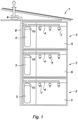
- a collective dwelling 1 equipped with a domestic hot water production facility is represented at the figure 1 .
- the dwelling comprises a plurality of housing 2 distributed over several floors. Only one dwelling 2 per floor is represented at the figure 1 for reasons of readability.
- Each housing 2 comprises a water heater comprising a reservoir 3 inside which is stored a fluid to be heated.
- Each housing 2 is furthermore equipped with at least one air extraction duct 4, in particular at the level of the technical parts 5, as is better represented in FIG. figure 2 .
- the air extraction pipe 4 of each housing 2 is connected to an air extraction network 8 common to the various housings, the air extraction network 8 comprising an upper part equipped with a fan 9.
- each housing 2 comprises heat exchange means 10 arranged to heat the fluid contained in the tank 3 from the extracted air flowing in the pipe 4.
- the insufflation and the extraction of air are controlled simultaneously.
- This is called dual flow ventilation.
- the air inlets are made, not at the level of the windows, but at the level of air intakes arranged in the living rooms 12.
- the heat exchange means 10 comprise a thermodynamic circuit 13 inside which circulates a refrigerant.
- the thermodynamic circuit 13 comprises successively, in the direction of flow of refrigerant, an evaporator 14 disposed in the pipe 4 and arranged to exchange heat with the extracted air, a compressor 15, a condenser 16 arranged to exchange heat with the fluid contained in the reservoir 3, and a regulator 17.
- the direction of circulation of the refrigerant is represented by arrows.
- the phase and pressure of the refrigerant are identified by the references VBP (Steam Low Pressure), VHP (High Pressure Steam), LHP (High Pressure Liquid) and LBP (Low Pressure Liquid).
- the condenser 16 has the shape of a serpentine and is disposed inside the tank 3 of the water heater, so as to exchange heat directly with the fluid contained in the tank 3.
- the installation further comprises a heat exchanger of the double flow type 18, in which the flow of blown air F1 into the housing 2 exchanges heat with the extracted air flow F2 of the housing 2.
- the double flow heat exchanger 18 makes it possible to exchange heat between the incoming air flow F1 coming from the air blowing network 11 and directed towards the housing 2 via a distribution pipe individual 19 for distributing the air blown into the various living rooms 12, and the outgoing air flow F2 from the technical parts 5, conveyed from these different parts by the air extraction pipe 4, and directed to the air extraction network 8.
- the heat exchanger of the double flow type 18 is disposed upstream of the evaporator 14 of the thermodynamic circuit 13, in the direction of circulation of the extracted air.
- the installation comprises recycling means 20 for directing a portion of the air blown from the insufflation network 11 directly into the air extraction network 8, that is to say without rejecting it in the housing 2.
- the recycling means are located upstream of the evaporator, in the direction of circulation of the extracted air, and comprise a controlled valve and a bypass branch for diverting the air blown out of the double flow heat exchanger 18.
- the condenser 16 is disposed outside the tank 3.
- the heat exchange means 10 then further comprise a secondary circuit 21 for heat exchange, equipped with a pump 22 and inside which circulates a coolant.
- the secondary circuit 21 passes through the condenser 16 so as to exchange heat with the coolant.
- the secondary circuit 21 further comprises a heat exchanger 23 in the form of a coil disposed inside the tank 3 of the water heater, so as to exchange heat with the fluid contained in the tank 3 .
- the structure of the heat exchange means 10 is described above in combination with a double flow type ventilation. However, the structure of the heat exchange means 10 remains unchanged in the case of single flow ventilation, only the air supply network 11 and the double flow type heat exchanger 18 being in this case non-existent .
- the installation according to the invention makes it possible to recover, at least in part, the heat energy available in the extracted air so as to transfer it to the fluid contained in the tank in order to produce hot water with high efficiency.
- such an installation can be adapted to collective dwellings, because of the use of an air extraction network common to the different housing to which each corresponding air exhaust duct is connected.
Landscapes
- Engineering & Computer Science (AREA)
- Chemical & Material Sciences (AREA)
- Combustion & Propulsion (AREA)
- Mechanical Engineering (AREA)
- General Engineering & Computer Science (AREA)
- Physics & Mathematics (AREA)
- Thermal Sciences (AREA)
- Life Sciences & Earth Sciences (AREA)
- Sustainable Development (AREA)
- Heat-Pump Type And Storage Water Heaters (AREA)
- Bidet-Like Cleaning Device And Other Flush Toilet Accessories (AREA)
Priority Applications (1)
| Application Number | Priority Date | Filing Date | Title |
|---|---|---|---|
| PL09703886T PL2232155T3 (pl) | 2008-01-22 | 2009-01-19 | Instalacja do wytwarzania gorącej wody użytkowej dla budynku mieszkalnego wielorodzinnego |
Applications Claiming Priority (2)
| Application Number | Priority Date | Filing Date | Title |
|---|---|---|---|
| FR0800315A FR2926626B1 (fr) | 2008-01-22 | 2008-01-22 | Installation de production d'eau chaude sanitaire pour une habitation collective |
| PCT/FR2009/050065 WO2009092976A2 (fr) | 2008-01-22 | 2009-01-19 | Installation de production d'eau chaude sanitaire pour une habitation collective |
Publications (2)
| Publication Number | Publication Date |
|---|---|
| EP2232155A2 EP2232155A2 (fr) | 2010-09-29 |
| EP2232155B1 true EP2232155B1 (fr) | 2019-12-04 |
Family
ID=39673416
Family Applications (1)
| Application Number | Title | Priority Date | Filing Date |
|---|---|---|---|
| EP09703886.3A Active EP2232155B1 (fr) | 2008-01-22 | 2009-01-19 | Installation de production d'eau chaude sanitaire pour une habitation collective |
Country Status (7)
| Country | Link |
|---|---|
| US (1) | US20110023517A1 (pl) |
| EP (1) | EP2232155B1 (pl) |
| CA (1) | CA2712189A1 (pl) |
| ES (1) | ES2774179T3 (pl) |
| FR (1) | FR2926626B1 (pl) |
| PL (1) | PL2232155T3 (pl) |
| WO (1) | WO2009092976A2 (pl) |
Families Citing this family (16)
| Publication number | Priority date | Publication date | Assignee | Title |
|---|---|---|---|---|
| US8805597B2 (en) * | 2009-02-10 | 2014-08-12 | Steffes Corporation | Electrical appliance energy consumption control |
| FR2962794B1 (fr) * | 2010-07-15 | 2014-11-21 | Anjos Ventilation | Procede de controle d'une installation de traitement d'air et installation utilisant une telle methode |
| FR2966565B1 (fr) | 2010-10-25 | 2012-12-07 | Atlantic Climatisation Et Ventilation | Installation de production d’eau chaude sanitaire pour habitation collective et procede de mise en oeuvre d’une telle installation |
| FR2966563B1 (fr) * | 2010-10-25 | 2012-12-21 | Atlantic Climatisation Et Ventilation | Installation de production d'eau chaude sanitaire pour habitation collective |
| FR2966564A1 (fr) | 2010-10-25 | 2012-04-27 | Atlantic Climatisation Et Ventilation | Installation de production d'eau chaude sanitaire pour habitation collective comprenant un ventilateur d'extraction d'air commun |
| FR2972246B1 (fr) * | 2011-03-04 | 2013-03-15 | Aldes Aeraulique | Installation de production d'eau chaude sanitaire exploitant une technologie thermodynamique dans une habitation collective et procede adapte de gestion de la ventilation |
| FR2982345B1 (fr) * | 2011-11-04 | 2018-01-19 | Atlantic Climatisation Et Ventilation | Installations de production d'eau chaude |
| FR2984998B1 (fr) * | 2011-12-27 | 2014-01-24 | France Air | Caisson de traitement d'air |
| FR2998353B1 (fr) * | 2012-11-20 | 2014-12-19 | Aldes Aeraulique | Procede et dispositif de rafraichissement de l'air dans une habitation et procede de fonctionnement |
| EP2778542A1 (fr) * | 2013-03-12 | 2014-09-17 | BDR Thermea Group | Installation de production d'eau chaude sanitaire dans une habitation via un chauffe-eau thermodynamique sur air extrait. |
| BE1021689B1 (nl) * | 2013-09-25 | 2016-01-08 | Renson Ventilation Nv | Klimatisatie-inrichting en werkwijze voor het aansturen van een dergelijke klimatisatie-inrichting |
| CA3142753C (en) | 2014-01-31 | 2025-02-11 | Steffes, Llc | ENERGY CONSUMPTION MANAGEMENT OF AN ENERGY STORAGE DEVICE |
| FR3017192B1 (fr) * | 2014-02-06 | 2019-01-25 | France Air | Installation de production d'eau chaude et procede de pilotage d'une telle installation |
| WO2019064335A1 (ja) * | 2017-09-26 | 2019-04-04 | 三菱電機株式会社 | 冷凍サイクル装置 |
| US11209199B2 (en) * | 2019-02-07 | 2021-12-28 | Heatcraft Refrigeration Products Llc | Cooling system |
| EP4680898A1 (de) * | 2023-03-16 | 2026-01-21 | SAM 365 GmbH | System zur wassertemperierung einer nutzungseinheit und wassertemperierungsvorrichtung hierfür |
Family Cites Families (19)
| Publication number | Priority date | Publication date | Assignee | Title |
|---|---|---|---|---|
| FR2356098A1 (fr) * | 1975-11-19 | 1978-01-20 | Costa Mario | Dispositif de transfert de chaleur d'un milieu aeraulique a un milieu hydraulique |
| FR2602310B1 (fr) | 1986-07-31 | 1988-11-10 | Roussel Michel | Dispositif de transmission d'un signal de securite collective pour un reseau d'extraction mecanique d'air et de gaz de combustion d'un ensemble de locaux d'habitation |
| FI83134C (fi) * | 1987-12-18 | 1991-05-27 | Ilmaterae Oy | Foerfarande och anordning foer reglering av luftstroemmar och tryck i luftkonditionering. |
| SE8901045L (sv) * | 1989-03-23 | 1990-09-24 | Givent Roger Ericsson Ab | Foerfarande och anordning foer temperaturreglering i en byggnad |
| US5056712A (en) * | 1989-12-06 | 1991-10-15 | Enck Harry J | Water heater controller |
| US5050394A (en) * | 1990-09-20 | 1991-09-24 | Electric Power Research Institute, Inc. | Controllable variable speed heat pump for combined water heating and space cooling |
| DE4412844C2 (de) * | 1994-02-09 | 1999-06-17 | Stiebel Eltron Gmbh & Co Kg | Klimagerät |
| DE29706131U1 (de) * | 1997-04-07 | 1997-05-22 | Hoose, Heinz Dieter, 45721 Haltern | Wärmepumpen/Klima-Anlage mit Wärmerückgewinnung |
| FR2763390B1 (fr) * | 1997-05-13 | 1999-07-23 | Andre Amphoux | Systeme de ventilation avec injection d'air supplementaire pour l'aide au tirage |
| DE29710913U1 (de) * | 1997-06-23 | 1997-09-25 | Hoose, Heinz Dieter, 45721 Haltern | Wärmepumpen-Anlage mit Zulufterwärmung |
| FR2769693B1 (fr) | 1997-10-14 | 1999-12-17 | Aldes Aeraulique | Systeme de ventilation a double flux |
| DE19819639C2 (de) * | 1998-05-05 | 2000-05-31 | Caldyn Apparatebau Gmbh | Beheizung von Passivhäusern |
| DE10058273A1 (de) * | 2000-11-23 | 2002-05-29 | Woelfle Gmbh | Vorrichtung zur Lüftung von Gebäuden nach dem Oberbegriff des Anspruchs 1 |
| DE20300465U1 (de) * | 2003-01-10 | 2003-07-24 | Erlus Baustoffwerke AG, 84088 Neufahrn | Be- und Entlüftungsanlage mit Gegenstrombetrieb |
| JP3918786B2 (ja) * | 2003-07-30 | 2007-05-23 | 株式会社デンソー | 貯湯式ヒートポンプ給湯装置 |
| EP1711751A1 (en) | 2004-02-06 | 2006-10-18 | J.E. Stork Ventilatoren B.V. | Method and apparatus for cooling ventilation air to be supplied to a space |
| FR2870326B1 (fr) | 2004-05-14 | 2006-07-28 | France Air | Installation pour le chauffage, le rafraichissement et la ventilation de logements collectifs |
| DE202004008792U1 (de) * | 2004-06-02 | 2004-08-26 | K.C.R. 28 Küchen und mehr GmbH | Zentrales Lüftungssystem zur Lüftung eines Wohngebäudes |
| DE102006019175B4 (de) * | 2006-04-21 | 2008-05-08 | Stiebel Eltron Gmbh & Co. Kg | Wärmepumpenvorrichtung |
-
2008
- 2008-01-22 FR FR0800315A patent/FR2926626B1/fr not_active Expired - Fee Related
-
2009
- 2009-01-19 US US12/864,085 patent/US20110023517A1/en not_active Abandoned
- 2009-01-19 EP EP09703886.3A patent/EP2232155B1/fr active Active
- 2009-01-19 CA CA2712189A patent/CA2712189A1/fr not_active Abandoned
- 2009-01-19 PL PL09703886T patent/PL2232155T3/pl unknown
- 2009-01-19 WO PCT/FR2009/050065 patent/WO2009092976A2/fr not_active Ceased
- 2009-01-19 ES ES09703886T patent/ES2774179T3/es active Active
Non-Patent Citations (1)
| Title |
|---|
| None * |
Also Published As
| Publication number | Publication date |
|---|---|
| ES2774179T3 (es) | 2020-07-17 |
| WO2009092976A3 (fr) | 2009-09-17 |
| WO2009092976A2 (fr) | 2009-07-30 |
| EP2232155A2 (fr) | 2010-09-29 |
| US20110023517A1 (en) | 2011-02-03 |
| FR2926626B1 (fr) | 2010-06-25 |
| PL2232155T3 (pl) | 2020-05-18 |
| CA2712189A1 (fr) | 2009-07-30 |
| FR2926626A1 (fr) | 2009-07-24 |
Similar Documents
| Publication | Publication Date | Title |
|---|---|---|
| EP2232155B1 (fr) | Installation de production d'eau chaude sanitaire pour une habitation collective | |
| EP3371516B1 (en) | A district thermal energy distribution system | |
| EP2312227B1 (fr) | Installation de ventilation mécanique contrôlée de type double flux thermodynamique réversible avec production d'eau chaude sanitaire | |
| FR2947896A1 (fr) | Installation de chauffage et/ou de fourniture d'eau chaude sanitaire | |
| WO2014044864A1 (fr) | Installation de chauffe-eau sanitaire à fonction de chauffage | |
| EP3969819B1 (fr) | Systeme d'interconnexion hydraulique pour reseau thermique | |
| EP2306107A1 (fr) | Système et procédé de ventilation double flux de production d'eau chaude sanitaire et de chauffage compact à pompe à chaleur intégrée | |
| FR2938900A1 (fr) | Dispositif de conditionnement d'air comportant un puit canadien et un echangeur de chaleur secondaire | |
| FR2922632A1 (fr) | Installation de ventilation mecanique controlee de type double flux thermodynamique reversible | |
| EP2232156B1 (fr) | Installation de production d'eau chaude sanitaire | |
| EP4644801A1 (fr) | Installation thermique multifonctionnelle, comprenant une pompe à chaleur à quantité réduite de fluide frigorigène | |
| FR3057651B1 (fr) | Installation de production d’eau chaude sanitaire pour une construction collective | |
| EP3139100B1 (fr) | Installation et procédé de production d'eau chaude associés | |
| EP2241827B1 (fr) | Installation et procédé de co-génération utilisant une pile à combustible pour le chauffage et la production d'eau chaude sanitaire | |
| FR3064725B1 (fr) | Installation pour les besoins thermiques d’un batiment en eau sanitaire et chauffage comprenant un chauffage thermodynamique | |
| BE1026742B1 (fr) | Procédé de transfert d'énergie de condensation de la vapeur d'eau de fumées de cogénération | |
| FR3072767A1 (fr) | Machine thermodynamique pourvue d'un echangeur de degivrage | |
| EP2743601B1 (fr) | Module intérieur compact pour installation de régulation thermique à pompe à chaleur | |
| EP2461108B1 (fr) | Dispositif de chaudière murale, équipement de chauffage d'un fluide, installation de chauffage d'un local et procédé d'adaptation d'un dispositif de chaudière murale | |
| CN104048349A (zh) | 用于利用红外线采暖装置为建筑物供暖的方法和设备 | |
| FR2947895A3 (fr) | Installation de chauffage et/ou de fourniture d'eau chaude sanitaire | |
| EP3745046B1 (fr) | Panoplie et panneau de raccordement pour dispositif hydraulique de régulation thermique | |
| FR2913755A1 (fr) | Dispositif de ventilation pour echangeur thermique | |
| FR2913757A1 (fr) | Dispositif de couplage d'un systeme de chauffage a liquide caloporteur a un dispositif de refroidissement | |
| EP3032180B1 (fr) | Dispositif thermique et procédé d'utilisation d'un tel dispositif |
Legal Events
| Date | Code | Title | Description |
|---|---|---|---|
| PUAI | Public reference made under article 153(3) epc to a published international application that has entered the european phase |
Free format text: ORIGINAL CODE: 0009012 |
|
| 17P | Request for examination filed |
Effective date: 20100628 |
|
| AK | Designated contracting states |
Kind code of ref document: A2 Designated state(s): AT BE BG CH CY CZ DE DK EE ES FI FR GB GR HR HU IE IS IT LI LT LU LV MC MK MT NL NO PL PT RO SE SI SK TR |
|
| AX | Request for extension of the european patent |
Extension state: AL BA RS |
|
| RIN1 | Information on inventor provided before grant (corrected) |
Inventor name: BUSEYNE, SERGE Inventor name: LABAUME, DAMIEN |
|
| TPAC | Observations filed by third parties |
Free format text: ORIGINAL CODE: EPIDOSNTIPA |
|
| DAX | Request for extension of the european patent (deleted) | ||
| STAA | Information on the status of an ep patent application or granted ep patent |
Free format text: STATUS: EXAMINATION IS IN PROGRESS |
|
| 17Q | First examination report despatched |
Effective date: 20170404 |
|
| GRAP | Despatch of communication of intention to grant a patent |
Free format text: ORIGINAL CODE: EPIDOSNIGR1 |
|
| STAA | Information on the status of an ep patent application or granted ep patent |
Free format text: STATUS: GRANT OF PATENT IS INTENDED |
|
| INTG | Intention to grant announced |
Effective date: 20190821 |
|
| GRAS | Grant fee paid |
Free format text: ORIGINAL CODE: EPIDOSNIGR3 |
|
| GRAA | (expected) grant |
Free format text: ORIGINAL CODE: 0009210 |
|
| STAA | Information on the status of an ep patent application or granted ep patent |
Free format text: STATUS: THE PATENT HAS BEEN GRANTED |
|
| AK | Designated contracting states |
Kind code of ref document: B1 Designated state(s): AT BE BG CH CY CZ DE DK EE ES FI FR GB GR HR HU IE IS IT LI LT LU LV MC MK MT NL NO PL PT RO SE SI SK TR |
|
| REG | Reference to a national code |
Ref country code: GB Ref legal event code: FG4D Free format text: NOT ENGLISH |
|
| REG | Reference to a national code |
Ref country code: CH Ref legal event code: EP |
|
| REG | Reference to a national code |
Ref country code: AT Ref legal event code: REF Ref document number: 1209886 Country of ref document: AT Kind code of ref document: T Effective date: 20191215 |
|
| REG | Reference to a national code |
Ref country code: DE Ref legal event code: R096 Ref document number: 602009060609 Country of ref document: DE |
|
| REG | Reference to a national code |
Ref country code: IE Ref legal event code: FG4D Free format text: LANGUAGE OF EP DOCUMENT: FRENCH |
|
| REG | Reference to a national code |
Ref country code: NL Ref legal event code: MP Effective date: 20191204 |
|
| REG | Reference to a national code |
Ref country code: LT Ref legal event code: MG4D |
|
| PG25 | Lapsed in a contracting state [announced via postgrant information from national office to epo] |
Ref country code: LV Free format text: LAPSE BECAUSE OF FAILURE TO SUBMIT A TRANSLATION OF THE DESCRIPTION OR TO PAY THE FEE WITHIN THE PRESCRIBED TIME-LIMIT Effective date: 20191204 Ref country code: SE Free format text: LAPSE BECAUSE OF FAILURE TO SUBMIT A TRANSLATION OF THE DESCRIPTION OR TO PAY THE FEE WITHIN THE PRESCRIBED TIME-LIMIT Effective date: 20191204 Ref country code: NO Free format text: LAPSE BECAUSE OF FAILURE TO SUBMIT A TRANSLATION OF THE DESCRIPTION OR TO PAY THE FEE WITHIN THE PRESCRIBED TIME-LIMIT Effective date: 20200304 Ref country code: FI Free format text: LAPSE BECAUSE OF FAILURE TO SUBMIT A TRANSLATION OF THE DESCRIPTION OR TO PAY THE FEE WITHIN THE PRESCRIBED TIME-LIMIT Effective date: 20191204 Ref country code: BG Free format text: LAPSE BECAUSE OF FAILURE TO SUBMIT A TRANSLATION OF THE DESCRIPTION OR TO PAY THE FEE WITHIN THE PRESCRIBED TIME-LIMIT Effective date: 20200304 Ref country code: LT Free format text: LAPSE BECAUSE OF FAILURE TO SUBMIT A TRANSLATION OF THE DESCRIPTION OR TO PAY THE FEE WITHIN THE PRESCRIBED TIME-LIMIT Effective date: 20191204 Ref country code: GR Free format text: LAPSE BECAUSE OF FAILURE TO SUBMIT A TRANSLATION OF THE DESCRIPTION OR TO PAY THE FEE WITHIN THE PRESCRIBED TIME-LIMIT Effective date: 20200305 |
|
| PG25 | Lapsed in a contracting state [announced via postgrant information from national office to epo] |
Ref country code: HR Free format text: LAPSE BECAUSE OF FAILURE TO SUBMIT A TRANSLATION OF THE DESCRIPTION OR TO PAY THE FEE WITHIN THE PRESCRIBED TIME-LIMIT Effective date: 20191204 |
|
| REG | Reference to a national code |
Ref country code: ES Ref legal event code: FG2A Ref document number: 2774179 Country of ref document: ES Kind code of ref document: T3 Effective date: 20200717 |
|
| PG25 | Lapsed in a contracting state [announced via postgrant information from national office to epo] |
Ref country code: EE Free format text: LAPSE BECAUSE OF FAILURE TO SUBMIT A TRANSLATION OF THE DESCRIPTION OR TO PAY THE FEE WITHIN THE PRESCRIBED TIME-LIMIT Effective date: 20191204 Ref country code: CZ Free format text: LAPSE BECAUSE OF FAILURE TO SUBMIT A TRANSLATION OF THE DESCRIPTION OR TO PAY THE FEE WITHIN THE PRESCRIBED TIME-LIMIT Effective date: 20191204 Ref country code: NL Free format text: LAPSE BECAUSE OF FAILURE TO SUBMIT A TRANSLATION OF THE DESCRIPTION OR TO PAY THE FEE WITHIN THE PRESCRIBED TIME-LIMIT Effective date: 20191204 Ref country code: RO Free format text: LAPSE BECAUSE OF FAILURE TO SUBMIT A TRANSLATION OF THE DESCRIPTION OR TO PAY THE FEE WITHIN THE PRESCRIBED TIME-LIMIT Effective date: 20191204 Ref country code: PT Free format text: LAPSE BECAUSE OF FAILURE TO SUBMIT A TRANSLATION OF THE DESCRIPTION OR TO PAY THE FEE WITHIN THE PRESCRIBED TIME-LIMIT Effective date: 20200429 |
|
| PG25 | Lapsed in a contracting state [announced via postgrant information from national office to epo] |
Ref country code: SK Free format text: LAPSE BECAUSE OF FAILURE TO SUBMIT A TRANSLATION OF THE DESCRIPTION OR TO PAY THE FEE WITHIN THE PRESCRIBED TIME-LIMIT Effective date: 20191204 Ref country code: IS Free format text: LAPSE BECAUSE OF FAILURE TO SUBMIT A TRANSLATION OF THE DESCRIPTION OR TO PAY THE FEE WITHIN THE PRESCRIBED TIME-LIMIT Effective date: 20200404 |
|
| REG | Reference to a national code |
Ref country code: CH Ref legal event code: PL |
|
| REG | Reference to a national code |
Ref country code: DE Ref legal event code: R097 Ref document number: 602009060609 Country of ref document: DE |
|
| REG | Reference to a national code |
Ref country code: AT Ref legal event code: MK05 Ref document number: 1209886 Country of ref document: AT Kind code of ref document: T Effective date: 20191204 |
|
| PG25 | Lapsed in a contracting state [announced via postgrant information from national office to epo] |
Ref country code: MC Free format text: LAPSE BECAUSE OF FAILURE TO SUBMIT A TRANSLATION OF THE DESCRIPTION OR TO PAY THE FEE WITHIN THE PRESCRIBED TIME-LIMIT Effective date: 20191204 |
|
| PLBE | No opposition filed within time limit |
Free format text: ORIGINAL CODE: 0009261 |
|
| STAA | Information on the status of an ep patent application or granted ep patent |
Free format text: STATUS: NO OPPOSITION FILED WITHIN TIME LIMIT |
|
| REG | Reference to a national code |
Ref country code: BE Ref legal event code: MM Effective date: 20200131 |
|
| PG25 | Lapsed in a contracting state [announced via postgrant information from national office to epo] |
Ref country code: LU Free format text: LAPSE BECAUSE OF NON-PAYMENT OF DUE FEES Effective date: 20200119 Ref country code: DK Free format text: LAPSE BECAUSE OF FAILURE TO SUBMIT A TRANSLATION OF THE DESCRIPTION OR TO PAY THE FEE WITHIN THE PRESCRIBED TIME-LIMIT Effective date: 20191204 |
|
| 26N | No opposition filed |
Effective date: 20200907 |
|
| PG25 | Lapsed in a contracting state [announced via postgrant information from national office to epo] |
Ref country code: SI Free format text: LAPSE BECAUSE OF FAILURE TO SUBMIT A TRANSLATION OF THE DESCRIPTION OR TO PAY THE FEE WITHIN THE PRESCRIBED TIME-LIMIT Effective date: 20191204 Ref country code: BE Free format text: LAPSE BECAUSE OF NON-PAYMENT OF DUE FEES Effective date: 20200131 Ref country code: CH Free format text: LAPSE BECAUSE OF NON-PAYMENT OF DUE FEES Effective date: 20200131 Ref country code: AT Free format text: LAPSE BECAUSE OF FAILURE TO SUBMIT A TRANSLATION OF THE DESCRIPTION OR TO PAY THE FEE WITHIN THE PRESCRIBED TIME-LIMIT Effective date: 20191204 Ref country code: LI Free format text: LAPSE BECAUSE OF NON-PAYMENT OF DUE FEES Effective date: 20200131 |
|
| PG25 | Lapsed in a contracting state [announced via postgrant information from national office to epo] |
Ref country code: IT Free format text: LAPSE BECAUSE OF FAILURE TO SUBMIT A TRANSLATION OF THE DESCRIPTION OR TO PAY THE FEE WITHIN THE PRESCRIBED TIME-LIMIT Effective date: 20191204 Ref country code: IE Free format text: LAPSE BECAUSE OF NON-PAYMENT OF DUE FEES Effective date: 20200119 |
|
| GBPC | Gb: european patent ceased through non-payment of renewal fee |
Effective date: 20200304 |
|
| PG25 | Lapsed in a contracting state [announced via postgrant information from national office to epo] |
Ref country code: GB Free format text: LAPSE BECAUSE OF NON-PAYMENT OF DUE FEES Effective date: 20200304 |
|
| PG25 | Lapsed in a contracting state [announced via postgrant information from national office to epo] |
Ref country code: TR Free format text: LAPSE BECAUSE OF FAILURE TO SUBMIT A TRANSLATION OF THE DESCRIPTION OR TO PAY THE FEE WITHIN THE PRESCRIBED TIME-LIMIT Effective date: 20191204 Ref country code: MT Free format text: LAPSE BECAUSE OF FAILURE TO SUBMIT A TRANSLATION OF THE DESCRIPTION OR TO PAY THE FEE WITHIN THE PRESCRIBED TIME-LIMIT Effective date: 20191204 Ref country code: CY Free format text: LAPSE BECAUSE OF FAILURE TO SUBMIT A TRANSLATION OF THE DESCRIPTION OR TO PAY THE FEE WITHIN THE PRESCRIBED TIME-LIMIT Effective date: 20191204 |
|
| PG25 | Lapsed in a contracting state [announced via postgrant information from national office to epo] |
Ref country code: MK Free format text: LAPSE BECAUSE OF FAILURE TO SUBMIT A TRANSLATION OF THE DESCRIPTION OR TO PAY THE FEE WITHIN THE PRESCRIBED TIME-LIMIT Effective date: 20191204 |
|
| P01 | Opt-out of the competence of the unified patent court (upc) registered |
Effective date: 20230526 |
|
| PGFP | Annual fee paid to national office [announced via postgrant information from national office to epo] |
Ref country code: PL Payment date: 20240105 Year of fee payment: 16 |
|
| PGFP | Annual fee paid to national office [announced via postgrant information from national office to epo] |
Ref country code: DE Payment date: 20241230 Year of fee payment: 17 |
|
| PGFP | Annual fee paid to national office [announced via postgrant information from national office to epo] |
Ref country code: ES Payment date: 20250414 Year of fee payment: 17 |
|
| PGFP | Annual fee paid to national office [announced via postgrant information from national office to epo] |
Ref country code: FR Payment date: 20260116 Year of fee payment: 18 |