EP2232307B1 - Laserzeigesystem - Google Patents
Laserzeigesystem Download PDFInfo
- Publication number
- EP2232307B1 EP2232307B1 EP08862886A EP08862886A EP2232307B1 EP 2232307 B1 EP2232307 B1 EP 2232307B1 EP 08862886 A EP08862886 A EP 08862886A EP 08862886 A EP08862886 A EP 08862886A EP 2232307 B1 EP2232307 B1 EP 2232307B1
- Authority
- EP
- European Patent Office
- Prior art keywords
- target
- mirror
- towards
- zone
- imaging system
- Prior art date
- Legal status (The legal status is an assumption and is not a legal conclusion. Google has not performed a legal analysis and makes no representation as to the accuracy of the status listed.)
- Active
Links
Images


Classifications
-
- G—PHYSICS
- G02—OPTICS
- G02B—OPTICAL ELEMENTS, SYSTEMS OR APPARATUS
- G02B5/00—Optical elements other than lenses
- G02B5/08—Mirrors
-
- G—PHYSICS
- G01—MEASURING; TESTING
- G01S—RADIO DIRECTION-FINDING; RADIO NAVIGATION; DETERMINING DISTANCE OR VELOCITY BY USE OF RADIO WAVES; LOCATING OR PRESENCE-DETECTING BY USE OF THE REFLECTION OR RERADIATION OF RADIO WAVES; ANALOGOUS ARRANGEMENTS USING OTHER WAVES
- G01S7/00—Details of systems according to groups G01S13/00, G01S15/00, G01S17/00
- G01S7/48—Details of systems according to groups G01S13/00, G01S15/00, G01S17/00 of systems according to group G01S17/00
- G01S7/481—Constructional features, e.g. arrangements of optical elements
- G01S7/4811—Constructional features, e.g. arrangements of optical elements common to transmitter and receiver
-
- G—PHYSICS
- G02—OPTICS
- G02B—OPTICAL ELEMENTS, SYSTEMS OR APPARATUS
- G02B23/00—Telescopes, e.g. binoculars; Periscopes; Instruments for viewing the inside of hollow bodies; Viewfinders; Optical aiming or sighting devices
- G02B23/14—Viewfinders
-
- G—PHYSICS
- G02—OPTICS
- G02B—OPTICAL ELEMENTS, SYSTEMS OR APPARATUS
- G02B27/00—Optical systems or apparatus not provided for by any of the groups G02B1/00 - G02B26/00, G02B30/00
- G02B27/10—Beam splitting or combining systems
- G02B27/1006—Beam splitting or combining systems for splitting or combining different wavelengths
-
- G—PHYSICS
- G02—OPTICS
- G02B—OPTICAL ELEMENTS, SYSTEMS OR APPARATUS
- G02B27/00—Optical systems or apparatus not provided for by any of the groups G02B1/00 - G02B26/00, G02B30/00
- G02B27/10—Beam splitting or combining systems
- G02B27/1086—Beam splitting or combining systems operating by diffraction only
- G02B27/1093—Beam splitting or combining systems operating by diffraction only for use with monochromatic radiation only, e.g. devices for splitting a single laser source
-
- G—PHYSICS
- G02—OPTICS
- G02B—OPTICAL ELEMENTS, SYSTEMS OR APPARATUS
- G02B27/00—Optical systems or apparatus not provided for by any of the groups G02B1/00 - G02B26/00, G02B30/00
- G02B27/10—Beam splitting or combining systems
- G02B27/14—Beam splitting or combining systems operating by reflection only
- G02B27/143—Beam splitting or combining systems operating by reflection only using macroscopically faceted or segmented reflective surfaces
-
- G—PHYSICS
- G02—OPTICS
- G02B—OPTICAL ELEMENTS, SYSTEMS OR APPARATUS
- G02B27/00—Optical systems or apparatus not provided for by any of the groups G02B1/00 - G02B26/00, G02B30/00
- G02B27/10—Beam splitting or combining systems
- G02B27/14—Beam splitting or combining systems operating by reflection only
- G02B27/148—Beam splitting or combining systems operating by reflection only including stacked surfaces having at least one double-pass partially reflecting surface
-
- G—PHYSICS
- G02—OPTICS
- G02B—OPTICAL ELEMENTS, SYSTEMS OR APPARATUS
- G02B27/00—Optical systems or apparatus not provided for by any of the groups G02B1/00 - G02B26/00, G02B30/00
- G02B27/32—Fiducial marks and measuring scales within the optical system
Definitions
- the invention relates to a pointing system of a laser and in particular a medium power laser. It also relates to a laser imaging system and a pointing system of several optical sources.
- imaging systems it is known to use imaging systems to have an image of the target and the point of impact of the treatment beam on the target.
- the system can then change the orientation of the treatment beam according to the image obtained.
- the known systems In order to perform this imaging, the known systems generally transmit an illumination beam towards the target.
- An imaging system receives light reflected from the target and identifies the position of the target.
- the transmissions of the processing beam and the illumination beam often use the same optical circuits.
- the reception by the imaging system can therefore be disturbed by the transmission system of the processing beam, especially when the target is small.
- the invention makes it possible to solve this drawback.
- the invention is more particularly applicable in sighting systems in which a reflection system makes it possible to use the same optics for transmitting the treatment beam and for imaging.
- the mirror M2 provides a dual function: fine stabilization of the pointing through CT and from the signals from CA and shift of the treatment beam to avoid the disturbance provided by the shadow zone.
- said processing beam is transmitted through a non-reflective zone of a first mirror, said mirror enabling the reflection of the light reflected by the target to be returned to the imaging system.
- This zone of low reflection coefficient of the first mirror induces a shadow zone towards the imaging system.
- said angularly offset angle of the treatment beam corresponds, in the imaging device, to the diameter of said shadow zone.
- the system of the invention comprises a third mirror intended to reflect towards the target the light received from the second mirror, or conversely to reflect towards the second mirror the light received from the target, this third mirror making it possible to adjust the focus of the beam received from the second mirror.
- the system of the invention comprises a fourth mirror receiving the light received from the first mirror and reflecting it towards the imaging system.
- said treatment beam is at a first wavelength or range of wavelengths
- said illumination beam is at a second wavelength or range of wavelengths.
- the system further includes a spectral filter located between the first mirror and the imaging system and allowing transmission of the second wavelength or wavelength range only to the imaging system.
- the treatment laser source comprises an emitting optical fiber or an assembly of a plurality of emitting optical fibers, one end of which is flush with the said reflecting face.
- the surface of said end constituting said zone with little or no reflectivity.
- the reflecting face and the surface of said end are in the same plane and are inclined with respect to the axis of the emitting optical fiber or assembly of transmitting optical fibers.
- said first mirror comprises a face coated with a volume diffraction grating, which comprises a hole in said zone for the passage of said treatment beam and which exploits the conservation of the quasi-monochromatic character of the radiation emitted by the Laser lighting after reflection on the target to angularly separate the pathway treatment of the imaging pathway.
- an optical fiber 2 passes through a mirror M1.
- the reflecting surface 1 of the mirror M1 is provided with a non-reflective zone z1 (or little reflective compared to the whole of the surface 1) by which the fiber 2 can emit a processing light beam FS1 towards a localized area of a target C1.
- a non-reflective zone z1 or little reflective compared to the whole of the surface 1 by which the fiber 2 can emit a processing light beam FS1 towards a localized area of a target C1.
- an optical source can emit a light beam through this zone z1, but against the light incident on the mirror M1 is reflected by the reflective surface 1 except by the zone z1.
- the target C1 is illuminated by an imaging light beam FE1.
- the target C1 reflects a beam FR1.
- This is reflected by the surface 1 of the mirror M1 in the form of the beam FR2 to an imaging system or camera 3.
- the displayed image 4 is therefore the image of the target.
- the portion of the beam FR1 which reaches the mirror in the zone z1 is not (or practically not) reflected by the mirror M1.
- the imaging system of the figure 1 thus makes it possible to visualize the impact zone on the target C1 of the beam FS1 emitted by the optical fiber 2.
- an operator or an image processing system can thus modify the impact zone on the target by modifying the orientation and / or focusing of the beam FS1.
- the figure 2a represents the image on a camera screen (in phantom in the figure) of an illumination zone EC by the imaging beam (FE1 on the figure 1 ). Inside the EC zone, there is the treatment spot SP emitted source S1 which is in a shadow zone or blind area ZA as explained above.
- the blind zone ZA is smaller than the target and the spot SP can be located on the target.
- the image of the target C3 is entirely contained in the blind zone ZA and is therefore not visible or is hardly visible with the aid of the camera.
- the image obtained by the camera thus does not make it possible to precisely locate the position of the target and in particular the impact zone of the treatment beam on the target.
- the invention therefore relates to a method that overcomes this disadvantage.
- the method of the invention therefore provides for pre-pointing the processing beam FS1 towards the target.
- This pre-score is made according to known techniques and does not require great precision.
- the method of the invention then consists in angularly shifting the processing beam FS2 ( figure 2 ) of a known angle so as to shift, in the image of the camera, the blind zone with respect to the target by a distance D1 at least equal to the diameter of the blind zone.
- the image obtained is such that, instead of having the blind zone (in phantom in the figure) located on the target C3, it is now shifted by a distance D1.
- the camera can see an image such as that of the figure 2d where we can see on the one hand the target C3 and on the other hand the blind zone ZA.
- the spot of the treatment beam SP was indicated in the center of the blind zone ZA.
- the distance D2 is measured between the center of the blind zone (which corresponds to the center of the spot of the treatment beam) and a determined area P1 of the target C3 that is desired to be treated with the treatment beam.
- an inverse angular offset of the treatment beam is made at an angle corresponding to the distance D2 thus determined.
- the system can then transmit the processing beam to the target area P1
- the disturbance on the treatment beam may not exceed 150 ⁇ s every millisecond or 15% of the time during which the treatment laser can be neutralized on emission so as not to penalize the overall efficiency while ensuring photonic isolation of the camera vis-à-vis the laser treatment.
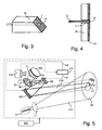
- the mirror M1 can be made using a block in which a fiber 2 has been embedded.
- a face 1 of the block B1 is machined in a plane inclined relative to the axis of the fiber 2.
- This face 1 is then made reflective (metallized for example) and in the reflecting surface obtained, the zone z1 is made non-reflective. For this, for example, a sufficiently energetic light beam is transmitted by the fiber 2 to deteriorate the reflective surface at the location of the zone z1.
- the figure 4 represents an alternative embodiment of the mirror M1. It comprises a support blade S1, one side of which is coated with a layer of a polymer material in which a volume diffraction grating has been recorded (Bragg grating). In addition, a hole T1 passes through the support plate and the diffraction grating so as to allow the installation of a fiber (or a set of fibers) whose emission end allows light emission by the zone. z1.
- a source S1 emits a light beam FS1 through a first mirror M1.
- This mirror is such as the one described above with reference to Figures 3 and 4 .
- the zone of emission z1 of this beam light through the mirror is therefore not reflective or weakly reflective.
- a second mirror M2 for orienting the beam reflects it to a third mirror M3 which focuses the beam to the zone Z1 to deal with the target C1.
- a pointing control source E1 emits a light beam FE1 which illuminates the target C1 according to a zone of illumination Z2.
- This zone Z2 has a surface much greater than that of zone Z1 and encompasses the latter.
- At least part of the light of the beam FE1 is reflected by the target towards the mirror M3 which reflects it towards the mirror M2. This light is then reflected by the mirror M1, then by a mirror M4 to a CA camera.
- the zone z1 of the mirror M1 by which the beam FS1 has been emitted is not very reflective.
- the camera CA thus receives an image of the target in which the blind area ZA appears less bright or different in color than the rest of the image of the target.
- the image obtained by the camera thus makes it possible to locate the blind zone ZA.
- the system comprises a central control circuit CC which makes it possible to control a pre-pointing of the entire pointing system of the figure 5 so that the beams FS2 and FE1 are substantially directed to the target C1 to be treated.
- This pre-score is based on data provided by an IR imaging system that covers a field of 1 to 3 degrees with an accuracy of the order of 500 ⁇ radians for a standard deviation of 3 ⁇ .
- the illumination source emits the beam FE1 which is reflected by the target C1.
- the camera receives the image of the target.
- This image is transmitted to a processing circuit CT which identifies the dimension of the blind zone ZA and its position on the target.
- the processing circuit controls an angular offset of the mirror M2 angularly shifting the beam FS2 by such a value that in the camera, the blind area ZA is shifted by a distance at least equal to the diameter of the blind area.
- the image obtained by the camera is transmitted to the processing circuit CT which measures the distance between the center of the blind area and a selected area of the target C1 to be processed.
- the processing circuit CT then controls, by the link ct1, the orientation of the mirror M2 to adjust the direction of the beam FS2 as a function of the result of the measurement that has just been performed. It can also control, by the connection ct2, the mirror M3 to adjust the focus.
- the camera can use a camera operating on the spectral range 1.5 ⁇ m, operating at a rate of 1 kHz with a shutter synchronized system on the return of a short pulse (-0.5 ⁇ s) generated by a an illumination laser that provides an image day and night with a resolution on the target of 0.15 to 0.3m with a sampling rate adapted to the bandwidth required to correct the fluctuations of the atmospheric channel located between the optical emission and the target.
- the wavelengths emitted by the sources S1 and E1 are of different values.
- the wavelength emitted by the source E1 is not contained in the wavelength range of the source S1.
- the invention then provides a spectral filter F1 which allows the passage of the wavelength (or range of wavelengths) transmitted by the source E1 to the camera. This reduces the risks of wavelength returns of the beam FS2 and reflected by the target to avoid damaging the image captured by the camera.
- the emission wavelength of the source E1 may be 1.5 microns and the source S1 may emit around 1.08 micrometer.
Landscapes
- Physics & Mathematics (AREA)
- General Physics & Mathematics (AREA)
- Optics & Photonics (AREA)
- Engineering & Computer Science (AREA)
- Remote Sensing (AREA)
- Radar, Positioning & Navigation (AREA)
- Computer Networks & Wireless Communication (AREA)
- Astronomy & Astrophysics (AREA)
- Laser Surgery Devices (AREA)
- Length Measuring Devices By Optical Means (AREA)
- Laser Beam Processing (AREA)
- Optical Radar Systems And Details Thereof (AREA)
- Telescopes (AREA)
- Lenses (AREA)
Claims (7)
- Laserstrahlzeigesystem, dadurch gekennzeichnet, dass es Folgendes umfasst:- wenigstens eine Verarbeitungslaserquelle (S1) zum Aussenden eines Verarbeitungslaserstrahls (FS1, FS2) in Richtung auf ein Ziel (C1), wobei der Verarbeitungsstrahl (FS1) durch eine nichtreflektierende Zone (z1) eines ersten Spiegels (M1) übertragen wird, wobei der Spiegel (M1) die Rückkehr in Richtung eines Bilderzeugungssystems (CA) zulässt, das einen von dem Ziel reflektierten Beleuchtungsstrahl (FR2) empfängt, wobei die Zone (z1) mit niedrigem Reflexionskoeffizient des ersten Spiegels (M1) eine Schattenzone (ZA) zu dem Bilderzeugungssystem (CA) hin induziert;- einen zweiten Spiegel (M2), der den Verarbeitungsstrahl empfängt, um den Strahl in Richtung des Ziels zu orientieren und zu reflektieren;- eine Beleuchtungsquelle (E1) zum Beleuchten des Ziels mit dem Beleuchtungsstrahl (FE1);- eine erste Steuerschaltung (CC) zum Steuern der Orientierung des Zeigesystems in Richtung Ziel;- eine zweite Steuerschaltung (CT) zum winkelmäßigen Verschieben des Verarbeitungsstrahls (FS1) in einem bestimmten Winkel zum Messen der Distanz (D2) zwischen der Position einer Zone (P1) des Ziels und der Position des Punkts des Verarbeitungsstrahls auf der Basis eines von dem Bilderzeugungssystem erhaltenen Bildes, dann Verschieben des Verarbeitungsstrahls in der entgegengesetzten Richtung in einem Winkel, der der gemessenen Distanz (D2) entspricht, wobei die Winkelverschiebung des Verarbeitungsstrahls eine solche Amplitude hat, dass die Messung der Position des Ziels durch die Schattenzone nicht gestört wird;- wobei der zweite Spiegel (M2) eine Doppelfunktion des Feinstabilisierens des Zeigens durch die zweite Steuerschaltung (CT) und auf der Basis der von dem Bilderzeugungssystem (CA) kommenden Signale und des Verschiebens des Verarbeitungsstrahls hat, um die von der Schattenzone verursachte Störung zu vermeiden.
- System nach Anspruch 1, dadurch gekennzeichnet, dass der Winkel, um den der Verarbeitungsstrahl (FS1) winkelmäßig verschoben ist, dem Durchmesser der Schattenzone (ZA) in der Bilderzeugungsvorrichtung (CA) entspricht.
- System nach Anspruch 2, dadurch gekennzeichnet, dass es einen dritten Spiegel (M3) zum Reflektieren des vom zweiten Spiegel (M2) empfangenen Lichts in Richtung Ziel (C1) oder umgekehrt zum Reflektieren des vom Ziel empfangenen Lichts in Richtung des zweiten Spiegels umfasst, wobei der dritte Spiegel (M3) das Justieren der Fokussierung des vom zweiten Spiegel (M2) empfangenen Strahls zulässt.
- System nach Anspruch 3, dadurch gekennzeichnet, dass es einen vierten Spiegel (M4) umfasst, der das vom ersten Spiegel (M1) empfangene Licht empfängt und es in Richtung des Bilderzeugungssystems (CA) reflektiert.
- System nach einem der Ansprüche 1 bis 4, dadurch gekennzeichnet, dass der Verarbeitungsstrahl (FS1) eine erste Wellenlänge oder einen ersten Wellenlängenbereich hat, der Beleuchtungsstrahl (FE1) eine(n) zweite(n) Wellenlänge oder Wellenlängenbereich hat, die/der sich von der/dem ersten Wellenlänge oder Wellenlängenbereich unterscheidet, wobei das System ferner ein zwischen dem ersten Spiegel (M1) und dem Bilderzeugungssystem (CA) befindliches Spektralfilter (F1) umfasst und die/den zweite(n) Wellenlänge oder Wellenlängenbereich nur zum Bilderzeugungssystem durchlässt.
- System nach einem der Ansprüche 1 bis 5, dadurch gekennzeichnet, dass die Verarbeitungslaserquelle (S1) eine emittierende optische Faser oder ein Bündel von mehreren emittierenden optischen Fasern umfasst, von denen ein Ende mit der reflektierenden Fläche (1) bündig ist, wobei die Oberfläche dieses Endes die schwach oder nicht reflektierende Zone (z1) bildet, wobei die reflektierende Fläche und die Oberfläche dieses Endes in derselben Ebene liegen und relativ zur Achse der emittierenden optischen Faser oder des Bündels von emittierenden optischen Fasern geneigt sind.
- System nach einem der Ansprüche 1 bis 6, dadurch gekennzeichnet, dass der erste Spiegel (M1) eine Fläche aufweist, die mit einem Volumenbeugungsgitter beschichtet ist, das ein Loch in der Zone (z1) für die Passage des Verarbeitungsstrahls (FS1) aufweist, dessen Beugungseffizienz so bestimmt wird, dass die quasi-monochromatische Strahlung des vom Ziel reflektierten Beleuchtungslasers abgelenkt wird.
Applications Claiming Priority (2)
| Application Number | Priority Date | Filing Date | Title |
|---|---|---|---|
| FR0708842A FR2925175B1 (fr) | 2007-12-18 | 2007-12-18 | Procede de pointage d'un laser et systeme mettant en oeuvre le procede |
| PCT/EP2008/066926 WO2009077360A1 (fr) | 2007-12-18 | 2008-12-05 | Systeme de pointage d'un laser |
Publications (2)
| Publication Number | Publication Date |
|---|---|
| EP2232307A1 EP2232307A1 (de) | 2010-09-29 |
| EP2232307B1 true EP2232307B1 (de) | 2012-05-23 |
Family
ID=39832331
Family Applications (1)
| Application Number | Title | Priority Date | Filing Date |
|---|---|---|---|
| EP08862886A Active EP2232307B1 (de) | 2007-12-18 | 2008-12-05 | Laserzeigesystem |
Country Status (12)
| Country | Link |
|---|---|
| US (1) | US20100272320A1 (de) |
| EP (1) | EP2232307B1 (de) |
| JP (1) | JP2011507044A (de) |
| KR (1) | KR20100099293A (de) |
| CN (1) | CN101910883A (de) |
| CA (1) | CA2709811A1 (de) |
| ES (1) | ES2386396T3 (de) |
| FR (1) | FR2925175B1 (de) |
| IL (1) | IL206451A (de) |
| RU (1) | RU2010129440A (de) |
| WO (1) | WO2009077360A1 (de) |
| ZA (1) | ZA201004343B (de) |
Families Citing this family (3)
| Publication number | Priority date | Publication date | Assignee | Title |
|---|---|---|---|---|
| FR3035720B1 (fr) | 2015-04-30 | 2017-06-23 | Thales Sa | Systeme optique et procede de pointage laser a travers l'atmosphere |
| US10380395B2 (en) * | 2016-09-30 | 2019-08-13 | Synaptics Incorporated | Optical sensor with angled reflectors |
| US12253629B2 (en) | 2018-10-29 | 2025-03-18 | Nec Corporation | Sensor device and article display shelf |
Family Cites Families (13)
| Publication number | Priority date | Publication date | Assignee | Title |
|---|---|---|---|---|
| US1240300A (en) * | 1916-06-26 | 1917-09-18 | Robert M Blair | Sight for firearms. |
| US3574467A (en) * | 1969-07-09 | 1971-04-13 | Nasa | Method and apparatus for aligning a laser beam projector |
| GB1378852A (en) * | 1970-12-21 | 1974-12-27 | British Aircraft Corp Ltd | Missile guidance systems |
| FR2505505A1 (fr) * | 1981-05-08 | 1982-11-12 | Cilas | Dispositif laser pour detecter et neutraliser l'optique d'un appareil de reperage adverse |
| US4768873A (en) * | 1985-09-17 | 1988-09-06 | Eye Research Institute Of Retina Foundation | Double scanning optical apparatus and method |
| US5918305A (en) * | 1997-08-27 | 1999-06-29 | Trw Inc. | Imaging self-referencing tracker and associated methodology |
| IL133835A (en) * | 1999-12-30 | 2003-10-31 | Rafael Armament Dev Authority | In-flight boresight |
| US6973355B2 (en) * | 2001-04-25 | 2005-12-06 | Tisue J Gilbert | Accurate positioner suitable for sequential agile tuning of pulse burst and CW lasers |
| US7172290B2 (en) * | 2003-06-09 | 2007-02-06 | Wavien, Inc. | Light pipe based projection engine |
| EP1649564A4 (de) * | 2003-07-03 | 2007-09-05 | Pd Ld Inc | Verwendung von volumen-bragg-gittern zur aufbereitung von laseremissionskenngrössen |
| US7569824B2 (en) * | 2004-06-03 | 2009-08-04 | Bae Systems Information And Electronic Systems Integration Inc. | Laser beam steering system and method for use in a directional infrared countermeasures system |
| US7652752B2 (en) * | 2005-07-14 | 2010-01-26 | Arete' Associates | Ultraviolet, infrared, and near-infrared lidar system and method |
| FR2925174B1 (fr) * | 2007-12-18 | 2010-02-19 | Thales Sa | Miroir d'imagerie, procede de fabrication et application a un systeme d'imagerie laser |
-
2007
- 2007-12-18 FR FR0708842A patent/FR2925175B1/fr not_active Expired - Fee Related
-
2008
- 2008-12-05 US US12/809,278 patent/US20100272320A1/en not_active Abandoned
- 2008-12-05 WO PCT/EP2008/066926 patent/WO2009077360A1/fr not_active Ceased
- 2008-12-05 CA CA2709811A patent/CA2709811A1/en not_active Abandoned
- 2008-12-05 CN CN2008801246302A patent/CN101910883A/zh active Pending
- 2008-12-05 ES ES08862886T patent/ES2386396T3/es active Active
- 2008-12-05 EP EP08862886A patent/EP2232307B1/de active Active
- 2008-12-05 JP JP2010538554A patent/JP2011507044A/ja active Pending
- 2008-12-05 KR KR1020107015741A patent/KR20100099293A/ko not_active Withdrawn
- 2008-12-05 RU RU2010129440/28A patent/RU2010129440A/ru unknown
-
2010
- 2010-06-17 IL IL206451A patent/IL206451A/en active IP Right Grant
- 2010-06-18 ZA ZA2010/04343A patent/ZA201004343B/en unknown
Also Published As
| Publication number | Publication date |
|---|---|
| ES2386396T3 (es) | 2012-08-20 |
| US20100272320A1 (en) | 2010-10-28 |
| IL206451A0 (en) | 2010-12-30 |
| IL206451A (en) | 2014-09-30 |
| EP2232307A1 (de) | 2010-09-29 |
| RU2010129440A (ru) | 2012-01-27 |
| ZA201004343B (en) | 2011-03-30 |
| KR20100099293A (ko) | 2010-09-10 |
| WO2009077360A1 (fr) | 2009-06-25 |
| CA2709811A1 (en) | 2009-06-25 |
| CN101910883A (zh) | 2010-12-08 |
| JP2011507044A (ja) | 2011-03-03 |
| FR2925175B1 (fr) | 2010-02-19 |
| FR2925175A1 (fr) | 2009-06-19 |
Similar Documents
| Publication | Publication Date | Title |
|---|---|---|
| EP0291394B1 (de) | Bewegungssensor mit zurückgesetzten optischen Fasern | |
| EP0419320B1 (de) | Vorrichtung zur automatischen Harmonisierung für ein opto-elektronisches System | |
| EP0205359B1 (de) | Optoelektronischer Zweirichtungsbauteil, der einen optischen Koppler bildet | |
| EP3439529B1 (de) | Vorrichtungen und verfahren zur weiterleitung und steuerung von lichtstrahlen für linsenlose endomikroskopische bildgebung | |
| EP2232307B1 (de) | Laserzeigesystem | |
| FR2797042A1 (fr) | Procede et dispositif de guidage a balayage laser d'un missile vers une cible | |
| CA3128728C (fr) | Injection d'un faisceau de rayonnement dans une fibre optique | |
| EP2804032A1 (de) | Optische Vorrichtung mit Schnellverschluss | |
| EP2232308B1 (de) | Bildgebendes lasersystem | |
| FR2848664A1 (fr) | Detecteur de position, forme et reflectivite d'une surface | |
| EP4291935B1 (de) | Beobachtungssystem und -verfahren, und herstellungsverfahren eines solchen systems | |
| FR2689254A1 (fr) | Dispositif de focalisation d'un faisceau lumineux. | |
| FR3071069B1 (fr) | Dispositif de telemetrie laser monostatique | |
| FR2803027A1 (fr) | Procede de mesure optique pour la mesure sans contact d'epaisseur de materiaux translucides, et dispositif associe | |
| EP1808665B1 (de) | Telemetrische Laser-Zielvorrichtung | |
| FR2567651A1 (fr) | Equipement de mesure de vitesse d'un projectile par interferometrie utilisant un faisceau laser propage par un guide d'onde optique unique | |
| EP3977158B1 (de) | Lidar-system mit einem interferenziellen diffraktiven element und lidar-abbildungsverfahren | |
| EP0844495A1 (de) | Vorrichtung zur Detektion von darauf gerichteten optischen Elementen | |
| FR2736731A1 (fr) | Dispositif de detection d'organes optiques pointes sur le dispositif | |
| FR2730823A1 (fr) | Procede et dispositif de reglage d'un montage de collimation par miroir parabolique hors d'axe | |
| FR3017218A1 (fr) | Procedes et dispositifs de controle de la taille de faisceaux lumineux de grandes dimensions | |
| FR2730818A1 (fr) | Telemetre laser a effet larsen comportant notamment une optique unique d'emission et de reception | |
| CH648930A5 (en) | Method and device for measuring the deviation in the position of a surface | |
| EP1542037A1 (de) | Lidar Beobachtungsgerät mit Laserprüfstrahlanpassungsoptik | |
| FR2943430A1 (fr) | Optode pour un transducteur optique |
Legal Events
| Date | Code | Title | Description |
|---|---|---|---|
| PUAI | Public reference made under article 153(3) epc to a published international application that has entered the european phase |
Free format text: ORIGINAL CODE: 0009012 |
|
| 17P | Request for examination filed |
Effective date: 20100616 |
|
| AK | Designated contracting states |
Kind code of ref document: A1 Designated state(s): AT BE BG CH CY CZ DE DK EE ES FI FR GB GR HR HU IE IS IT LI LT LU LV MC MT NL NO PL PT RO SE SI SK TR |
|
| AX | Request for extension of the european patent |
Extension state: AL BA MK RS |
|
| DAX | Request for extension of the european patent (deleted) | ||
| REG | Reference to a national code |
Ref country code: DE Ref legal event code: R079 Ref document number: 602008015929 Country of ref document: DE Free format text: PREVIOUS MAIN CLASS: G02B0005080000 Ipc: G02B0027140000 |
|
| GRAP | Despatch of communication of intention to grant a patent |
Free format text: ORIGINAL CODE: EPIDOSNIGR1 |
|
| RIC1 | Information provided on ipc code assigned before grant |
Ipc: G02B 27/14 20060101AFI20111109BHEP |
|
| GRAS | Grant fee paid |
Free format text: ORIGINAL CODE: EPIDOSNIGR3 |
|
| GRAA | (expected) grant |
Free format text: ORIGINAL CODE: 0009210 |
|
| AK | Designated contracting states |
Kind code of ref document: B1 Designated state(s): AT BE BG CH CY CZ DE DK EE ES FI FR GB GR HR HU IE IS IT LI LT LU LV MC MT NL NO PL PT RO SE SI SK TR |
|
| REG | Reference to a national code |
Ref country code: GB Ref legal event code: FG4D Free format text: NOT ENGLISH |
|
| REG | Reference to a national code |
Ref country code: CH Ref legal event code: EP |
|
| REG | Reference to a national code |
Ref country code: AT Ref legal event code: REF Ref document number: 559332 Country of ref document: AT Kind code of ref document: T Effective date: 20120615 |
|
| REG | Reference to a national code |
Ref country code: IE Ref legal event code: FG4D Free format text: LANGUAGE OF EP DOCUMENT: FRENCH |
|
| REG | Reference to a national code |
Ref country code: DE Ref legal event code: R096 Ref document number: 602008015929 Country of ref document: DE Effective date: 20120802 |
|
| REG | Reference to a national code |
Ref country code: ES Ref legal event code: FG2A Ref document number: 2386396 Country of ref document: ES Kind code of ref document: T3 Effective date: 20120820 |
|
| REG | Reference to a national code |
Ref country code: NL Ref legal event code: T3 |
|
| REG | Reference to a national code |
Ref country code: SE Ref legal event code: TRGR |
|
| REG | Reference to a national code |
Ref country code: LT Ref legal event code: MG4D Effective date: 20120523 |
|
| PG25 | Lapsed in a contracting state [announced via postgrant information from national office to epo] |
Ref country code: FI Free format text: LAPSE BECAUSE OF FAILURE TO SUBMIT A TRANSLATION OF THE DESCRIPTION OR TO PAY THE FEE WITHIN THE PRESCRIBED TIME-LIMIT Effective date: 20120523 Ref country code: NO Free format text: LAPSE BECAUSE OF FAILURE TO SUBMIT A TRANSLATION OF THE DESCRIPTION OR TO PAY THE FEE WITHIN THE PRESCRIBED TIME-LIMIT Effective date: 20120823 Ref country code: IS Free format text: LAPSE BECAUSE OF FAILURE TO SUBMIT A TRANSLATION OF THE DESCRIPTION OR TO PAY THE FEE WITHIN THE PRESCRIBED TIME-LIMIT Effective date: 20120923 Ref country code: LT Free format text: LAPSE BECAUSE OF FAILURE TO SUBMIT A TRANSLATION OF THE DESCRIPTION OR TO PAY THE FEE WITHIN THE PRESCRIBED TIME-LIMIT Effective date: 20120523 Ref country code: CY Free format text: LAPSE BECAUSE OF FAILURE TO SUBMIT A TRANSLATION OF THE DESCRIPTION OR TO PAY THE FEE WITHIN THE PRESCRIBED TIME-LIMIT Effective date: 20120523 |
|
| REG | Reference to a national code |
Ref country code: AT Ref legal event code: MK05 Ref document number: 559332 Country of ref document: AT Kind code of ref document: T Effective date: 20120523 |
|
| PG25 | Lapsed in a contracting state [announced via postgrant information from national office to epo] |
Ref country code: LV Free format text: LAPSE BECAUSE OF FAILURE TO SUBMIT A TRANSLATION OF THE DESCRIPTION OR TO PAY THE FEE WITHIN THE PRESCRIBED TIME-LIMIT Effective date: 20120523 Ref country code: SI Free format text: LAPSE BECAUSE OF FAILURE TO SUBMIT A TRANSLATION OF THE DESCRIPTION OR TO PAY THE FEE WITHIN THE PRESCRIBED TIME-LIMIT Effective date: 20120523 Ref country code: GR Free format text: LAPSE BECAUSE OF FAILURE TO SUBMIT A TRANSLATION OF THE DESCRIPTION OR TO PAY THE FEE WITHIN THE PRESCRIBED TIME-LIMIT Effective date: 20120824 Ref country code: PT Free format text: LAPSE BECAUSE OF FAILURE TO SUBMIT A TRANSLATION OF THE DESCRIPTION OR TO PAY THE FEE WITHIN THE PRESCRIBED TIME-LIMIT Effective date: 20120924 Ref country code: HR Free format text: LAPSE BECAUSE OF FAILURE TO SUBMIT A TRANSLATION OF THE DESCRIPTION OR TO PAY THE FEE WITHIN THE PRESCRIBED TIME-LIMIT Effective date: 20120523 |
|
| PG25 | Lapsed in a contracting state [announced via postgrant information from national office to epo] |
Ref country code: DK Free format text: LAPSE BECAUSE OF FAILURE TO SUBMIT A TRANSLATION OF THE DESCRIPTION OR TO PAY THE FEE WITHIN THE PRESCRIBED TIME-LIMIT Effective date: 20120523 Ref country code: SK Free format text: LAPSE BECAUSE OF FAILURE TO SUBMIT A TRANSLATION OF THE DESCRIPTION OR TO PAY THE FEE WITHIN THE PRESCRIBED TIME-LIMIT Effective date: 20120523 Ref country code: AT Free format text: LAPSE BECAUSE OF FAILURE TO SUBMIT A TRANSLATION OF THE DESCRIPTION OR TO PAY THE FEE WITHIN THE PRESCRIBED TIME-LIMIT Effective date: 20120523 Ref country code: EE Free format text: LAPSE BECAUSE OF FAILURE TO SUBMIT A TRANSLATION OF THE DESCRIPTION OR TO PAY THE FEE WITHIN THE PRESCRIBED TIME-LIMIT Effective date: 20120523 Ref country code: RO Free format text: LAPSE BECAUSE OF FAILURE TO SUBMIT A TRANSLATION OF THE DESCRIPTION OR TO PAY THE FEE WITHIN THE PRESCRIBED TIME-LIMIT Effective date: 20120523 Ref country code: CZ Free format text: LAPSE BECAUSE OF FAILURE TO SUBMIT A TRANSLATION OF THE DESCRIPTION OR TO PAY THE FEE WITHIN THE PRESCRIBED TIME-LIMIT Effective date: 20120523 |
|
| PG25 | Lapsed in a contracting state [announced via postgrant information from national office to epo] |
Ref country code: PL Free format text: LAPSE BECAUSE OF FAILURE TO SUBMIT A TRANSLATION OF THE DESCRIPTION OR TO PAY THE FEE WITHIN THE PRESCRIBED TIME-LIMIT Effective date: 20120523 |
|
| PLBE | No opposition filed within time limit |
Free format text: ORIGINAL CODE: 0009261 |
|
| STAA | Information on the status of an ep patent application or granted ep patent |
Free format text: STATUS: NO OPPOSITION FILED WITHIN TIME LIMIT |
|
| 26N | No opposition filed |
Effective date: 20130226 |
|
| REG | Reference to a national code |
Ref country code: DE Ref legal event code: R097 Ref document number: 602008015929 Country of ref document: DE Effective date: 20130226 |
|
| BERE | Be: lapsed |
Owner name: THALES Effective date: 20121231 |
|
| PG25 | Lapsed in a contracting state [announced via postgrant information from national office to epo] |
Ref country code: BG Free format text: LAPSE BECAUSE OF FAILURE TO SUBMIT A TRANSLATION OF THE DESCRIPTION OR TO PAY THE FEE WITHIN THE PRESCRIBED TIME-LIMIT Effective date: 20120823 Ref country code: MC Free format text: LAPSE BECAUSE OF NON-PAYMENT OF DUE FEES Effective date: 20121231 |
|
| REG | Reference to a national code |
Ref country code: CH Ref legal event code: PL |
|
| REG | Reference to a national code |
Ref country code: IE Ref legal event code: MM4A |
|
| PG25 | Lapsed in a contracting state [announced via postgrant information from national office to epo] |
Ref country code: BE Free format text: LAPSE BECAUSE OF NON-PAYMENT OF DUE FEES Effective date: 20121231 |
|
| PG25 | Lapsed in a contracting state [announced via postgrant information from national office to epo] |
Ref country code: IE Free format text: LAPSE BECAUSE OF NON-PAYMENT OF DUE FEES Effective date: 20121205 Ref country code: LI Free format text: LAPSE BECAUSE OF NON-PAYMENT OF DUE FEES Effective date: 20121231 Ref country code: CH Free format text: LAPSE BECAUSE OF NON-PAYMENT OF DUE FEES Effective date: 20121231 |
|
| PG25 | Lapsed in a contracting state [announced via postgrant information from national office to epo] |
Ref country code: MT Free format text: LAPSE BECAUSE OF FAILURE TO SUBMIT A TRANSLATION OF THE DESCRIPTION OR TO PAY THE FEE WITHIN THE PRESCRIBED TIME-LIMIT Effective date: 20120523 |
|
| PG25 | Lapsed in a contracting state [announced via postgrant information from national office to epo] |
Ref country code: TR Free format text: LAPSE BECAUSE OF FAILURE TO SUBMIT A TRANSLATION OF THE DESCRIPTION OR TO PAY THE FEE WITHIN THE PRESCRIBED TIME-LIMIT Effective date: 20120523 |
|
| PG25 | Lapsed in a contracting state [announced via postgrant information from national office to epo] |
Ref country code: LU Free format text: LAPSE BECAUSE OF NON-PAYMENT OF DUE FEES Effective date: 20121205 |
|
| PG25 | Lapsed in a contracting state [announced via postgrant information from national office to epo] |
Ref country code: HU Free format text: LAPSE BECAUSE OF FAILURE TO SUBMIT A TRANSLATION OF THE DESCRIPTION OR TO PAY THE FEE WITHIN THE PRESCRIBED TIME-LIMIT Effective date: 20081205 |
|
| REG | Reference to a national code |
Ref country code: FR Ref legal event code: PLFP Year of fee payment: 8 |
|
| REG | Reference to a national code |
Ref country code: FR Ref legal event code: PLFP Year of fee payment: 9 |
|
| REG | Reference to a national code |
Ref country code: FR Ref legal event code: PLFP Year of fee payment: 10 |
|
| P01 | Opt-out of the competence of the unified patent court (upc) registered |
Effective date: 20230529 |
|
| PGFP | Annual fee paid to national office [announced via postgrant information from national office to epo] |
Ref country code: NL Payment date: 20251126 Year of fee payment: 18 |
|
| PGFP | Annual fee paid to national office [announced via postgrant information from national office to epo] |
Ref country code: DE Payment date: 20251119 Year of fee payment: 18 |
|
| PGFP | Annual fee paid to national office [announced via postgrant information from national office to epo] |
Ref country code: GB Payment date: 20251113 Year of fee payment: 18 |
|
| PGFP | Annual fee paid to national office [announced via postgrant information from national office to epo] |
Ref country code: IT Payment date: 20251126 Year of fee payment: 18 |
|
| PGFP | Annual fee paid to national office [announced via postgrant information from national office to epo] |
Ref country code: FR Payment date: 20251124 Year of fee payment: 18 |
|
| PGFP | Annual fee paid to national office [announced via postgrant information from national office to epo] |
Ref country code: SE Payment date: 20251126 Year of fee payment: 18 |
|
| PGFP | Annual fee paid to national office [announced via postgrant information from national office to epo] |
Ref country code: ES Payment date: 20260114 Year of fee payment: 18 |