EP2232651B1 - Inline-verbinder - Google Patents
Inline-verbinder Download PDFInfo
- Publication number
- EP2232651B1 EP2232651B1 EP08858891.8A EP08858891A EP2232651B1 EP 2232651 B1 EP2232651 B1 EP 2232651B1 EP 08858891 A EP08858891 A EP 08858891A EP 2232651 B1 EP2232651 B1 EP 2232651B1
- Authority
- EP
- European Patent Office
- Prior art keywords
- canted
- connector
- bore
- housing
- retaining cylinder
- Prior art date
- Legal status (The legal status is an assumption and is not a legal conclusion. Google has not performed a legal analysis and makes no representation as to the accuracy of the status listed.)
- Active
Links
- 239000004020 conductor Substances 0.000 claims description 92
- 238000004891 communication Methods 0.000 claims description 9
- 230000000717 retained effect Effects 0.000 claims description 9
- 238000000034 method Methods 0.000 claims description 7
- 230000036961 partial effect Effects 0.000 claims description 7
- 230000008901 benefit Effects 0.000 description 4
- 238000003780 insertion Methods 0.000 description 4
- 230000037431 insertion Effects 0.000 description 4
- 230000000670 limiting effect Effects 0.000 description 4
- 239000000463 material Substances 0.000 description 4
- 230000003247 decreasing effect Effects 0.000 description 3
- 238000009434 installation Methods 0.000 description 3
- 230000014759 maintenance of location Effects 0.000 description 3
- 230000008439 repair process Effects 0.000 description 3
- 238000012986 modification Methods 0.000 description 2
- 230000004048 modification Effects 0.000 description 2
- 230000003647 oxidation Effects 0.000 description 2
- 238000007254 oxidation reaction Methods 0.000 description 2
- 238000012546 transfer Methods 0.000 description 2
- RYGMFSIKBFXOCR-UHFFFAOYSA-N Copper Chemical compound [Cu] RYGMFSIKBFXOCR-UHFFFAOYSA-N 0.000 description 1
- 229910000831 Steel Inorganic materials 0.000 description 1
- 229910052782 aluminium Inorganic materials 0.000 description 1
- XAGFODPZIPBFFR-UHFFFAOYSA-N aluminium Chemical compound [Al] XAGFODPZIPBFFR-UHFFFAOYSA-N 0.000 description 1
- 230000005540 biological transmission Effects 0.000 description 1
- 229910052802 copper Inorganic materials 0.000 description 1
- 239000010949 copper Substances 0.000 description 1
- 238000006073 displacement reaction Methods 0.000 description 1
- 230000007613 environmental effect Effects 0.000 description 1
- PCHJSUWPFVWCPO-UHFFFAOYSA-N gold Chemical compound [Au] PCHJSUWPFVWCPO-UHFFFAOYSA-N 0.000 description 1
- 239000010931 gold Substances 0.000 description 1
- 229910052737 gold Inorganic materials 0.000 description 1
- 230000005484 gravity Effects 0.000 description 1
- 231100001261 hazardous Toxicity 0.000 description 1
- 238000010438 heat treatment Methods 0.000 description 1
- 230000007774 longterm Effects 0.000 description 1
- 229910052751 metal Inorganic materials 0.000 description 1
- 239000002184 metal Substances 0.000 description 1
- 230000009467 reduction Effects 0.000 description 1
- 230000002829 reductive effect Effects 0.000 description 1
- 238000000926 separation method Methods 0.000 description 1
- 238000009751 slip forming Methods 0.000 description 1
- 239000007787 solid Substances 0.000 description 1
- 239000010959 steel Substances 0.000 description 1
- 238000004804 winding Methods 0.000 description 1
Images








Classifications
-
- H—ELECTRICITY
- H01—ELECTRIC ELEMENTS
- H01R—ELECTRICALLY-CONDUCTIVE CONNECTIONS; STRUCTURAL ASSOCIATIONS OF A PLURALITY OF MUTUALLY-INSULATED ELECTRICAL CONNECTING ELEMENTS; COUPLING DEVICES; CURRENT COLLECTORS
- H01R13/00—Details of coupling devices of the kinds covered by groups H01R12/70 or H01R24/00 - H01R33/00
- H01R13/46—Bases; Cases
- H01R13/533—Bases, cases made for use in extreme conditions, e.g. high temperature, radiation, vibration, corrosive environment, pressure
-
- H—ELECTRICITY
- H01—ELECTRIC ELEMENTS
- H01R—ELECTRICALLY-CONDUCTIVE CONNECTIONS; STRUCTURAL ASSOCIATIONS OF A PLURALITY OF MUTUALLY-INSULATED ELECTRICAL CONNECTING ELEMENTS; COUPLING DEVICES; CURRENT COLLECTORS
- H01R13/00—Details of coupling devices of the kinds covered by groups H01R12/70 or H01R24/00 - H01R33/00
- H01R13/02—Contact members
- H01R13/15—Pins, blades or sockets having separate spring member for producing or increasing contact pressure
-
- H—ELECTRICITY
- H01—ELECTRIC ELEMENTS
- H01R—ELECTRICALLY-CONDUCTIVE CONNECTIONS; STRUCTURAL ASSOCIATIONS OF A PLURALITY OF MUTUALLY-INSULATED ELECTRICAL CONNECTING ELEMENTS; COUPLING DEVICES; CURRENT COLLECTORS
- H01R13/00—Details of coupling devices of the kinds covered by groups H01R12/70 or H01R24/00 - H01R33/00
- H01R13/02—Contact members
- H01R13/15—Pins, blades or sockets having separate spring member for producing or increasing contact pressure
- H01R13/17—Pins, blades or sockets having separate spring member for producing or increasing contact pressure with spring member on the pin
-
- H—ELECTRICITY
- H01—ELECTRIC ELEMENTS
- H01R—ELECTRICALLY-CONDUCTIVE CONNECTIONS; STRUCTURAL ASSOCIATIONS OF A PLURALITY OF MUTUALLY-INSULATED ELECTRICAL CONNECTING ELEMENTS; COUPLING DEVICES; CURRENT COLLECTORS
- H01R13/00—Details of coupling devices of the kinds covered by groups H01R12/70 or H01R24/00 - H01R33/00
- H01R13/02—Contact members
- H01R13/15—Pins, blades or sockets having separate spring member for producing or increasing contact pressure
- H01R13/187—Pins, blades or sockets having separate spring member for producing or increasing contact pressure with spring member in the socket
-
- Y—GENERAL TAGGING OF NEW TECHNOLOGICAL DEVELOPMENTS; GENERAL TAGGING OF CROSS-SECTIONAL TECHNOLOGIES SPANNING OVER SEVERAL SECTIONS OF THE IPC; TECHNICAL SUBJECTS COVERED BY FORMER USPC CROSS-REFERENCE ART COLLECTIONS [XRACs] AND DIGESTS
- Y10—TECHNICAL SUBJECTS COVERED BY FORMER USPC
- Y10T—TECHNICAL SUBJECTS COVERED BY FORMER US CLASSIFICATION
- Y10T29/00—Metal working
- Y10T29/49—Method of mechanical manufacture
- Y10T29/49002—Electrical device making
- Y10T29/49117—Conductor or circuit manufacturing
- Y10T29/49194—Assembling elongated conductors, e.g., splicing, etc.
- Y10T29/49195—Assembling elongated conductors, e.g., splicing, etc. with end-to-end orienting
Definitions
- In-line mechanical, electrical, electromagnetic interference (EMI) and grounding connectors using canted coil springs offer significant advantages in applications requiring the mechanical, electrical, EMI or grounding connection of two elongated members or rods that are subjected to vibration, to extreme and highly variable temperatures, and that require a high degree of reliability.
- the rods are usually, although not required, cylindrical in configuration.
- connected conductive members such as rods
- conductive bars are adjacent to high speed or rotating applications, such as generators and motors, and. as such, may experience intense vibration.
- typical means of mechanical connection such as screw/threaded, hinged, and other jointed connections are limited to the amount of thermal expansion and vibration they can withstand and still perform sufficiently.
- components of connectors are made from different materials, such as copper and steel, a difference in thermal expansion between the two materials at high and variable temperatures often causes failure in such connectors since the greater expansion of one component can damage another component or result in loss of contact between components.
- screw/thread connectors are used, the variable thermal variation of the threaded components can cause the threaded portions to disengage from each other, and, in electrical applications, can increase the current resistance of electrical conductors, thus decreasing their current carrying capabilities.
- Canted-coil spring-loaded connectors may overcome limitations of conventional connection means.
- Canted-coil springs in connectors provide substantially constant contact force over a wide range of deflection when using radial canted-coil springs or variable contact force when using axial canted-coil springs, thereby tolerating differences in thermal expansions from wide temperature variations and retaining constant or variable force connections between members experiencing high speeds and intense vibration.
- Canted-coil spring loaded connectors can tolerate wide variations in misalignment since canted-coil springs can maintain constant contact during in-line axial, radial and angular offsets over an operating deflection range of the springs,
- the use of canted-coil springs in conjunction with tool-less housings, such as holding, latching, or locking means, allows for easy tool-less assembly and connection of canted-coil spring-loaded connectors and cylindrical conductive members.
- mechanical fasteners such as threaded screws or lock nuts, may be used in combination with spring-based connectors.
- Canted-coil spring loaded connectors can provide connection for in-line butted or in-line separated cylindrical members in mechanical, electrical, EMI, or grounding applications using conductive materials, and can comprise either a single moveable component, or numerous moveable components that allow the connector to be collapsible.
- Collapsible tool-less connector allow the connector to be compressed into a small package and to be assembled onto cylindrical members in tight and difficult to reach spaces or from awkward positions. Collapsible tool-less connectors may also be used when members to be connected are fixed and a space between members cannot be adjusted.
- Examples of applications of canted-coil spring loaded in-line collapsible electrical connectors include space applications where awkward positions and the absence of gravity make the installation or repair of electrical connectors difficult, especially in cases where multiple parts and tools are required. For example, astronauts assembling external spacecraft instruments and equipment may have difficulty handling numerous parts and tools.
- Other examples where tool-less canted-coil spring loaded collapsible connectors may be used include switch gear or bus bar connections in nuclear power plants since, in some areas, it may not be possible to bring tools into said areas as they can become contaminated. In solar energy applications, the electrical connectors used are replaced frequently in the field, and not by specialized companies, so tool-less connectors would provide a simple connection, quick installation time, and avoid the risk of miss-assembly.
- Instruments housed in closed quarters such as instrument panels and switch gears, are also good candidates for the connectors of the present invention.
- canted-coil spring(s) loaded in-line collapsible electrical connectors may be used where physical protection must be worn which may affect handling capabilities, such as in hazardous environments due to chemical exposure, radiation exposure, deep sea pressure, or extreme temperatures.
- Canted-coil springs are disclosed in U.S. patents 4,826,144 , 4,893,795 , 4,876,781 , 4,907,788 , 4,961,253 , 4,934,666 , 4.915,366 , 5,160,122 , 4,964,204 , 5,108,078 , 5,079,388 , 5,139,276 , 5,082.390 , 5,091,606 , 5,161.806 , 5,239,737 , 5,474,309 , 5,545,842 , 5,411,348 , 5,503,375 , 5,599,027 , 5,615.870 , 5,709,371 , 5,791.638 , 7,055,812 B2 , 6.835.084 B2 , and 7,272,964 .
- Such canted coil springs may be incorporated into connections having radial, axial, and angular springs with variable spring forces and made from different materials depending on the operating conditions in mechanical applications, electrical applications, or a combination thereof.
- the canted coil springs may be used to conduct current, and to retain, latch and lock components in mechanical or combination mechanical and electrical applications.
- canted-coil spring-loaded mechanical connectors for mechanical, electrical. EMI, grounding connections, or combinations thereof may result in or provide the following non-limiting useful benefits:
- aspects of the present invention include a tool-less in-line electrical connector comprising a housing having a longitudinal bore and a plurality of grooves spaced along an inner circumferential surface of the longitudinal bore; and a canted-coil spring positioned within each groove, each canted-coil spring dimensioned to contact a conductor pin inserted into the longitudinal bore.
- a tool-less in-line electrical connector comprising a housing comprising an outer sleeve defining a sleeve longitudinal bore including a first bore section having a first diameter and a second bore section having a second diameter adapted to receive a conductor pin; and an inner retaining cylinder slidable within the first bore section with respect to the outer sleeve, the first bore section and the second bore section having at least one groove along an inner circumferential surface containing a canted-coil spring; wherein the inner retaining cylinder defines a cylinder longitudinal bore coaxial with the sleeve longitudinal bore having at least one groove along an inner circumferential surface containing a canted-coil spring, the cylinder longitudinal bore adapted to receive a conductor pin.
- the electrical connector may optionally comprise a retaining groove around an outer circumferential surface of the retaining cylinder adapted to engage the canted-coil spring in the first bore section of the outer sleeve.
- a tool-less in-line electrical connector comprising a housing defining a longitudinal bore and a plurality of grooves spaced along an inner circumferential surface of the bore, each groove containing a canted-coil spring; and two connector pins slidable within the longitudinal bore, each connector pin having a base adapted to contact the inner circumferential surface of the housing and a receiving portion having at least one canted-coil spring within an inner circumferential groove, the receiving portion adapted to receive a conductor pin.
- a tool-less in-line electrical connector comprising a housing defining a longitudinal bore and a plurality of housing grooves spaced along an inner circumferential surface of the bore; and two connector pins slidable within the longitudinal bore, each connector pin including a base having a canted-coil spring within a groove, the canted-coil spring adapted to engage one housing groove, and a receiving portion having at least one canted-coil spring within an inner circumferential groove, the receiving portion dimensioned to receive a conductor pin.
- the present invention also includes a method for electrically communicating two conductor pins comprising pushing an end of a first conductor pin into a first bore comprising at least one canted-coil spring; pushing an end of a second conductor pin into a second bore comprising at least one canted coil spring; and sliding a conductor housing relative to either the first conductor pin or the second conductor pin or sliding a sleeve located inside the conductor housing relative to the conductor housing.
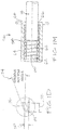
- FIGs. 1A-1M show a connector 10 useful for understanding the present invention.
- Connector 10 is suitable for connecting unthreaded butted cylindrical members, pins, or rods 12, 14 using biasing members for retention. Such connector permits axial and radial movement to tolerate wide variations in temperature as well as wide dimensional and position tolerances between members.
- the connector 10 may be used for mechanical, electrical, EMI, and/or grounding applications in which two in-line members are connected and retained together using frictional force, as provided by, for example, canted coil springs.
- the connector 10 may be used to connect two butted members without a tool.
- in-line what is meant is that two ends of two members may be positioned end to end but not necessarily in contact with one another or in perfect alignment. In other words, the two members may be positioned in-line with one another but offset.
- FIG. 1A shows the connector 10 comprising a housing 16 having a longitudinal bore 18.
- the connector 10 further comprises inner circumferential grooves, such as four grooves 20, 22, 24, 26, for housing biasing members 28, 30, 32, 34, respectively, which are preferably canted coil springs.
- the grooves 20, 22, 24, and 26 may embody any combination of contours discussed in the various patents incorporated above and as specifically shown in the accompanied figures, such as a tapered bottom groove 36 ( FIG. 1D ), a flat bottom groove 38 (FIG. IE), or v-bottom groove 40 (FIG. IF), to provide different forces in different directions.
- the canted-coil springs 28, 30, 32, and 34 may be any combination of or any one of radial, axial, and angular canted-coil springs to provide different forces, tolerances, and characteristics of conductivity. Furthermore, for a particular connector, a combination of different grooves (i.e., grooves with different characteristics, such as different bottom configurations) may be used.
- the connector 10 is mounted onto the elongated or cylindrical member 12, or the cylindrical member 12 is inserted into the bore 18 of the connector, such that canted-coil springs 28, 30, 32, and 34 are compressed or deflected along a radial direction of each individual coil of the canted-coil springs.
- the springs thus exert spring forces on the elongated member 12 at spaced apart intervals along the length of the elongated members to retain the elongated member 12 within the bore.
- the connector 10 is mounted onto two butted or generally axially aligned cylindrical members 12, 14.
- the first cylindrical member 12 is held by a first set of canted-coil springs 28, 30 while the second cylindrical member 14 is held by a second set of canted-coil springs 32, 34.
- the cylindrical members 12, 14, or one of the two members may comprise grooves 42 ( FIG. 1G ) along an exterior circumferential surface to engage the canted-coil springs 28, 30, 32, 34 to retain the cylindrical members within the housing 16.
- the grooves 42 shown generally in FIG. 1G , may be one of or any combination of a v-bottom groove 44 ( FIG. 1H ), a flat bottom groove 46 ( FIG.
- the connector 10 allows the transfer of electrical current between the two cylindrical members 12, 14, via through the springs and the housing, while providing mechanical stability by allowing axial and radial movement and thermal expansion between the two members.
- the springs and the housing(s) are understood to be made from conductive materials.
- the tool-less connector may be used in non conducting applications, such as for use to connect two tubing or pipe sections together, for connecting two components together, etc.
- FIG. 1D shows an enlarged view of canted-coil spring 34 housed in a spring groove 26 having a tapered bottom. Adjustments in groove height 50, groove width 52, and groove bottom angle 54 can vary the force of insertion and removal of cylindrical member 14 into and out of connector housing 16. Generally speaking, decreasing the groove height or groove width will increase the spring force of the canted-coil spring, and increasing the groove bottom angle increases the difference between insertion and removal force on the cylindrical members.
- the groove bottom angle may be formed on either side of the groove, i.e., inclined in either direction, to create a higher force in either direction. In other words, the groove bottom angle as shown in FIG. 1D may be a positive angle or a negative angle with respect to the surface of a cylindrical member inserted into the connector.
- an aspect of the present connector which is useful for understanding the present invention is understood to include a connector housing comprising a plurality of springs located in a plurality of grooves, the housing comprising a central bore for receiving two elongated members, and wherein the elongated members are in sliding contact with the springs and in electrical communication with one another.
- the connector is further understood to provide a space or gap for the expansion of one or both elongated members due to thermal expansion by allowing one or both to axially slide relative to the housing while maintaining electrical communication with one another. More preferably, the two elongated members are in electrical communication with one another without directly contacting one another.
- FIG. 1M shows another connector 56 useful for understanding the present invention.
- the connector 56 comprises a housing 58 having a longitudinal bore 60.
- a continuous threaded groove 62 which resembles a spiral wound thread, extends around an interior circumferential surface of the longitudinal bore 60 along at least a portion of a length of the entire connector, into which a canted-coil spring 64 is wound and retained.
- the canted-coil spring 64 is prevented from winding out of the open ends of the groove 62 by stakes 66, 68 formed at the entrance of the bore.
- the ends of the groove 62 may be welded to the ends of canted-coil spring 64 to retain the spring therein.
- an end flange or end plate may be bolted onto each end of the housing to retain the spring.
- Electrical current may be transferred between cylindrical members inserted into the connector 56, with only one member 14 shown.
- the connector 56 which comprises the housing 58 and the spring 64, provides means for electrical communication between two cylindrical members, rods, or pins and is configured for enhanced mechanical stability by allowing axial and radial movements and thermal expansion. For example, if the elongated member 14 expands due to heating, the connector easily accommodates the growth due to little or no solid abutment with the connector housing.
- a canted-coil spring wound into a threaded groove to provide circumferential force and to hold components or members in a connection assembly may be applied to any of the connectors described herein, as well as any other suitable connectors within the spirit and scope of the present invention.
- aspects of a connector useful for understanding the present invention are understood to comprise a housing having a first open end, a second open end, and an interior wall surface comprising two or more grooves, wherein a spring section is positioned in each of the two or more grooves, and wherein an elongated member projects through the first open end or the second open end and is adaptable to extend through the other one of the first open end or the second open end.
- the two or more grooves are part of a continuously formed groove such that the two or more grooves are in communication with each other.
- the spring section comprises a continuous spring coil.
- a second elongated member extends through the other one of the first open end or the second open end and wherein the elongated member and the second elongated member do not directly contact one another.
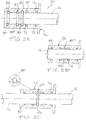
- FIGs. 2A-2D show another connector 70 useful for understanding the present invention.
- Connector 70 is suitable for connecting unthreaded cylindrical members 12, 14 ( FIG. 2C ), similar to the connector shown in FIG. 1A .
- the connector may be used for mechanical, electrical, EMI, and/or grounding applications and in a most preferred configuration is adapted for frictional retention of the elongated members. In particular configurations, the frictional retention force is generated from one or more springs.
- an aspect of the present connector is a connector housing configured to receive at least two elongated members and wherein the elongated members are axially movable relative to the housing and wherein the housing provides the means for electrical flow between the two elongated members.
- the connector permits axial and radial movements to accept wide variations in temperature as well as wide tolerances between the members, as further discussed below.
- FIG. 2A shows the connector 70 partially mounted on a cylindrical member 14 held in place by a plurality of canted-coil springs, such as two springs 72, 74 housed in spring grooves 76, 78.
- the connector 70 further comprises three additional grooves 80, 82, 84 for a total of five grooves, each groove housing a canted-coil spring 86, 88, 90, respectively.
- the grooves 80, 82, 84, 76, 78 may embody any one type or any combination of tapered, v-bottom, or flat bottom grooves to provide different forces in different directions.
- canted-coil springs 86, 88, 90, 72, 74 may be any one type or any combination of radial, axial, and angular canted-coil springs to provide different forces, tolerances, and characteristics of conductivity.
- FIG. 2B shows connector 70 mounted onto the cylindrical member 14, the size of which causes the canted-coil springs 86, 88, 90, 72, 74 to compress.
- FIG. 2C shows the assembled connector 70 mounted onto two cylindrical members 12, 14 wherein the first cylindrical member 12 is held by canted-coil springs 86, 88 and the second cylindrical member 14 is held by canted-coil springs 72, 74.
- the interior canted-coil spring 86 housed in the interior groove 80 provides a physical separation between the two cylindrical members 12, 14, yet since both cylindrical members contact the spring, electrical continuity can be maintained.
- an aspect of a connector useful for understanding the present invention is understood to include a connector housing comprising bore comprising a plurality of grooves having a plurality of springs located therein, which includes an interior groove and an interior spring; wherein two elongated members are located in the bore and held therein by the plurality of springs; and wherein the interior spring is in contact with both elongated members to provide a gap therebetween.
- the cylindrical members 12, 14 may comprise grooves formed around an exterior circumferential surface of the members similar to the grooves 42 shown in FIG. 1G to engage canted-coil springs 86, 88, 72, 74.
- the grooves may embody any one type or any combination of tapered, v-bottom, or flat bottom grooves to provide different forces in connecting and disconnecting and allow locking capabilities in addition to latching.
- the connector 70 may transfer electrical current between the two cylindrical members 12, 14 while providing mechanical stability by allowing axial and radial movement and thermal expansion.
- the connector is adapted to permit radial and axial expansions of the two elongated members by permitting relative axial and radial movements with the housing.
- the housing 92 is first slid completely over the first cylindrical member 14 ( FIG. 2B ) so that the second member 12 can then be aligned ( FIG. 2C ), at which point the housing 92 is slid back over the second member 12.
- the two cylindrical members may be inserted through the respective open ends of the housing 92.
- FIG. 2D shows another connector useful for understanding the present invention.
- the connector has a flat bottom groove 38 providing a decreased depth of canted-coil spring 86 in groove 38 and/or providing a higher spring force, particularly such that the spring force does not allow either cylindrical member 12 or 14 to penetrate past the spring 86, which acts as a stop in the center of the connector 70, unless a severe axial force is applied to the cylindrical member, such as to permanently deform the spring 86.
- assembly of the members involves inserting cylindrical members 12, 14 into the connector 70 from opposite ends of a longitudinal bore such that the cylindrical members do not have to be inserted over the spring 38. Note that in other configurations, the interior spring 86 may be penetrated or passed by providing a different groove configuration.
- FIGs. 3 through 9 show exemplary connector embodiments for connecting separated cylindrical members in accordance with aspects of the invention.
- These connectors incorporate various features, but preferably are designed to carry electrical current from one elongated member or conductor pin to another, while providing assembly, disassembly, and holding, latching, and/or locking capabilities to allow easy installation and repair in tight or difficult to reach spaces and under high temperature conditions.
- Many of today's current carrying applications may be under severe weather and temperature conditions in remote areas where reliability and assembly by means of a connection using tools may not be possible or practical.
- the connectors provided herein are configured to simplify and serve those applications in an efficient and useful manner.
- grooves incorporated in the connectors illustrated in FIGs. 3-9 may embody any one of or any combination of tapered, v-bottom, or flat bottom grooves to provide different forces in different directions.
- Canted-coil springs in the following connectors may be any one type or any combination of radial, axial, and angular canted-coil springs to provide different forces, tolerances, and characteristics of conductivity.
- a continuous circular groove may also be incorporated into the inner circumferential surface of the housing similar to the groove shown in FIG. 1M .
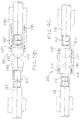
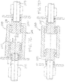
- FIGs. 3A-3D there are shown in the several figures a collapsible axial in-line electrical connector 94 that may be used with but preferably without a tool.
- the figures represent the assembly in different states or stages of assembly or disassembly.
- Canted-coil springs 96, 98 located within the circumferential housing 100 serve to retain, lock, and permit axial and radial movement of in-line conductor pins 102, 104 to allow variation in temperature and tolerances between conductor housings.
- the in-line electrical connector 94 includes a retaining cylinder 106 slidingly mounted within the circumferential housing 100 in a telescoping configuration. As further discussed below, this allows the connector to be collapsed to install, assemble, or disassemble the conductor pins.
- FIG. 3A shows the connector 94 in a collapsed configuration with the retaining cylinder 106 slid into the outer housing 100 and positioned for in-line assembly onto the conductor pin 102, which is attached to a pin housing 108, shown schematically only and may represent any number of shapes, sizes, and/or configurations.
- the connector is also ready for in-line assembly onto the second conductor pin 104, which is similarly attached to a pin housing 110.
- the connector 94 comprises the internal retaining cylinder 106 adapted to receive the conductor pin 102 and includes a plurality of springs, such as two canted-coil springs 96, mounted on an interior surface of the retaining cylinder 106 to retain the conductor pin therein.
- the retaining cylinder 106 is located within an outer sleeve circumferential housing 100 in which a plurality of canted-coil springs 112, such as two springs 112, are mounted and is retained by the canted-coil springs.
- the retaining cylinder 106 includes a retaining groove 107 adapted to receive canted-coil springs 112 to restrict the retaining cylinder 106 from disengaging from the housing 100 once engaged.
- FIG. 3B shows the connector 94 wherein conductor pin 104 has been assembled onto the housing 100, thereby radially compressing canted-coil springs 98 and being retained on the housing.
- FIG. 3C shows the connector 94 assembled onto the two pins 102, 104 with the internal retaining cylinder 106 fully extended and the canted-coil springs 112 engaging the retaining groove 107 on the cylinder to restrict axial movement of the retaining cylinder 106 and place the connector 94 in a firm loaded position.
- current can flow from the conductor pin 102 through canted-coil springs 96 and internal retaining cylinder 106, through canted springs 112, through circumferential housing 100 and canted-coil springs 98 and into conductor pin 104.
- the internal retaining cylinder 106 is collapsed back into circumferential housing 100, overcoming the spring force of canted springs 112. In such a position, the axial friction force of canted springs 96 may be overcome and the conductor pin 102 may be removed.
- FIG. 3D shows a degree of radial offset between the conductor pins 102, 104 caused by the radial deflection of springs 96, 112, and 98.
- the offset may be due to misalignment, warping, damage, and/or deflection of one or both of the conductor pins.
- the amount of offset may be about 0.030 inches.
- configurations allowing for more or less offset may be designed without departing from the spirit and scope of the invention.
- aspects of the present invention is a connector comprising a bore having a first spring positioned in a groove, a retaining cylinder comprising a bore having a second spring positioned in a groove and an exterior surface; wherein the exterior surface of the retaining cylinder is in sliding communication with the first spring and wherein the bore of the retaining cylinder is configured to receive a conductive elongated member.
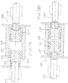
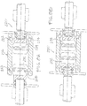
- FIGs. 4A-4D show another exemplary embodiment of an in-line collapsible connector with provisions for accommodating axial, radial and/or angular misalignment and usable without a tool.
- the connector 114 may include housing pins or retaining cylinders 116, 118 slidingly connected within a longitudinal bore of a circumferential housing 120, and axially retained therein by two outer axial canted-coil springs 122, 124.
- the housing pins 116, 118 each includes a partially spherical base 126 adapted to move in and out of a set of retaining springs 124 for placing the housing pin in either an extended position or a collapsed position.
- Each pin further includes a receiving portion 128, similar to a collar, adapted to receive a conductor pin 102 or 104.
- the receiving portion 128 includes canted-coil springs 130, 132 housed in spring grooves 134 for gripping the pins.
- the pins 102, 104 may incorporate grooves and the springs 130, 132 interact with the grooves on the conductor pins, (See, e.g., FIG. 1G ).
- a flange 136 extending from an end of the housing pins 116, 118 limits the distance which the housing pins can slide into the housing 120.
- FIG. 4B shows a first housing pin 118 of the connector 114 assembled onto a first conductor pin 104, the first housing pin being retained within the circumferential housing 120 by the deflection of canted-coil springs 124.
- FIG. 4C shows the offset 138 and angular displacement 140 that can be achieved while assembling the spherical housing pin 116 onto conductor pin 102 when the housing pins are in the collapsed position.
- the amount of offset may be about 0.040 inches.
- configurations allowing for more or less offset may be designed without departing from the spirit and scope of the invention.
- FIG. 4D shows the electrical connector 114 fully assembled with two spherical housing pins 116, 118 locked within the longitudinal bore by retaining canted-coil springs 122, 124, respectively.
- the connector 114 is fully extended and held in a locked position, restricting the axial movement of the pins 116, 118.
- the connector may be disassembled by moving the spherical housing pins 116, 118 toward each other (as shown in FIG. 4A ) and overcoming the radial springs force of axial springs 132, 124 and springs 130, 122.
- each housing pin further includes a collar comprising a groove and a spring located therein for receiving and providing a spring force on an elongated member.
- FIGs. 5A-5D show another exemplary embodiment of a non-collapsible in-line electrical connector 142 with provisions for accommodating axial, radial and/or angular misalignments, similar to the connector shown in FIGs. 4A-4D , but having threaded conductor pins 144, 146 and threaded connector pins or housing pins 148, 150.
- the connector 142 comprises a circumferential housing 152 with a longitudinal bore and a pair of grooves 154 housing canted-coil springs 156, 158, which engage housing pins 148, 150 and retain the housing pins within the housing.
- the housing pins 148, 150 which have a partial spherical base 160 and a threaded receiving section 162, are threaded to the conductor pins 144, 146 to electrically connect the conductor pins to the connector 142.
- FIG. 5C shows each threaded ball connector 148, 150 threaded to a respective connector pin 144, 146.
- FIG. 5D shows the angular maximum/minimum position of one exemplary embodiment that the ball connectors 148, 150 can accommodate relative to the connector pins, in addition to the permissible offset the ball connectors can have relative to the connector housing. Similar to the previously described embodiments, current flows from conductor pin 144 to conductor pin 146 through the piston mounted different components 148, 156, 152, and 150.
- each housing pin further includes a collar comprising internal threads for receiving and threading with a conductor member, such as a conductive pin.
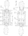
- FIGs. 6A , 6B, and 6C show another exemplary embodiment of an in-line collapsible electrical connector 164 with provisions for accommodating axial, radial and/or angular misalignment between the two conductor pins.
- the conductor pins each having an axial end surface, are typically positioned in abutting relationship to one another but generally do not contact and often are offset from one another, either axially, radially or both. Occasionally, thermal expansion can cause the two members to be offset.
- FIG. 6A shows the connector 164 in a collapsed position ready for assembly onto a first and a second conductor pins 166, 168.
- the connector 164 includes two ball connectors 170, 172 adapted to receive two conductor pins 166, 168 and permit electrical communication between the two through the circumferential housing 174. More specifically, ends of conductor pins 166, 168 include grooves 176, 178 which engage retaining springs 180, 182 to retain the conductor pins within the ball connectors 170, 172. Additionally, the ball connectors 170, 172 are slidable with respect or relative to the housing 174 between a recessed position ( FIG.
- FIG. 6A in which a tab 136 abuts an end of the housing 174 and an extended position ( FIGs. 6B and 6C ) in which a receiving portion 128 of the ball connectors 172, 170 extends from the housing.
- canted-coil springs 186, 188 are housed in spring grooves 190, 192 in the base.
- the canted-coil springs 186, 188 encounter grooves 194, 196 in the housing, the resistance created between the canted-coil springs and the grooves prevent the ball connectors 170, 172 from disengaging from the housing 164.
- FIG. 6C when the connector 164 is in the extended position, electrical current can flow from the first conductor pin 166 to second conductor pin 168 through the conductor 164 and into the power grid.
- FIGs. 7A, 7B , 7C, and 7D show another exemplary embodiment of an in-line collapsible electrical connector 198 with provisions for accommodating axial and/or radial misalignment and usable without a tool .
- the connector 198 includes two pin connectors 200, 202 slidable within a longitudinal bore of a housing 204, each pin connector is adapted to receive a conductor pin 104, 102.
- a base 210 of the pin connectors 200, 202 includes two grooves 212, each groove housing a canted-coil spring 214,216.
- the base resembles a barb connector and has at least one tooth having an outer diameter larger than the outer diameter of the collar section.
- the canted-coil springs 214, 216 engage grooves 218 in housing 204 which retains the pin connectors in the extended position.
- the pin connectors 200, 202 may be deflected such that their central axes are offset by about 0.05 inch.
- FIG. 7D when conductor pins 102, 104 are inserted into respective connector pins 202, 200, current flows between the conductor pins.
- the conductor pins 102, 104 may be disassembled by moving the bases 210 of the pin connectors 200 and 202 together, such as by grasping the two flanges or plates and moving them together.
- FIGs. 8A-8D show another exemplary embodiment of an in-line collapsible electrical connector 220 with provisions for accommodating misalignment and/or offset between two conductor pins, similar to the connector 164 shown in FIG. 6 .
- canted-coil springs 222 are mounted within bottom taper grooves 224 on a circumferential housing 226. When the canted-coil springs 222 engage a groove 228 on a generally or partially spherical base 230 of connector pins 232, 234, the canted-coil springs retain the connector pins within the circumferential housing 226.
- FIGs. 9A-9D show yet another exemplary embodiment of an in-line collapsible electrical connector 236 with provisions for accommodating misalignment and offset between two conductor pins.
- the configuration is similar to the connector 198 shown in FIG. 7 , but connector pins 238, 240 have a partially spherical base 242 with a single groove 244 containing a canted-coil spring 246.
- Such a configuration allows greater angular misalignment while allowing sufficient area of contact between the canted coil spring 246 and a circumferential housing 248 for the spring to carry electrical current through the connector 236.
- the connector pins 236, 240 can be maintained within the housing.
- Axial canted-coil springs generally develop greater concentrated loads at the points of contact than radial canted-coil springs, thereby reducing or eliminating the possibility of oxidation at such contact points, thus maintaining constant conductivity.
- the canted coil springs utilized are preferably axial canted coil springs.
- Threaded connectors when subject to thermal variations, typically have reduced torque for maintaining the connection. Such torque reduction may be accelerated by wide variations in temperature, and particularly by the variation in thermal expansion of the fastener holding the components together.
- the use of canted springs as a conductor as well as a holding, latching and locking means overcomes the thermal expansion problem due to the degree of flexibility available with such springs. Holding, latching and locking of the spring groove and spring itself can be made to any desired retained force based on spring force and groove configuration.
- housing, the springs, and housing pins are said to made from a conductive material to enable electrical communication between two conductive members
- the particular material types are not limited in anyway and may be made from any known conductive materials in the electrical art, such as from aluminum, metal, gold, etc. Additionally, specific aspects of one embodiment may be incorporated in a different embodiment provided they are compatible.
Landscapes
- Details Of Connecting Devices For Male And Female Coupling (AREA)
- Snaps, Bayonet Connections, Set Pins, And Snap Rings (AREA)
Claims (15)
- Elektrischer Inline-Verbinder (94) zur Bereitstellung elektrischer Kommunikation zwischen zwei leitfähigen Inline-Elementen, umfassend:ein Gehäuse (100), das eine äußere Muffe umfasst, die eine longitudinale Muffenbohrung definiert, die einen ersten Bohrungsabschnitt mit einem ersten Durchmesser und einen zweiten Bohrungsabschnitt mit einem zweiten Durchmesser umfasst;dadurch gekennzeichnet, dass es weiter umfasst:einen Rückhaltezylinder (106), der im ersten Bohrungsabschnitt der äußeren Muffe verschiebbar ist, wobei der erste Bohrungsabschnitt und der zweite Bohrungsabschnitt jeweils mindestens eine Nut aufweisen, die entlang einer inneren umlaufenden Oberfläche geformt ist und jede der mindestens einen Nut eine schräggewickelte Feder (98, 112) enthält;wobei der Haltezylinder (106) eine longitudinale Bohrung des Zylinders koaxial mit der longitudinalen Bohrung der Muffe definiert und mindestens eine Nut aufweist, die entlang einer inneren umlaufenden Oberfläche geformt ist und eine schräggewickelte Feder (96) enthält, wobei die longitudinale Bohrung des Zylinders angepasst ist, einen Leiterstift (102) aufzunehmen.
- Elektrischer Inline-Verbinder (94) nach Anspruch 1, ferner eine Haltenut um eine äußere umlaufende Oberfläche des Haltezylinders umfassend, die angepasst ist, die schräggewickelte Feder in den ersten Bohrungsabschnitt der äußeren Muffe einzurasten.
- Elektrischer Inline-Verbinder (94) nach Anspruch 1, wobei der Haltezylinder eine ausgefahrene Position, in der ein erheblicher Teil des Haltezylinders außerhalb der longitudinalen Bohrung der äußeren Muffe angeordnet ist und eine eingefahrene Position umfasst, in der ein erheblicher Teil des Haltezylinders innerhalb der longitudinalen Bohrung der äußeren Muffe angeordnet ist.
- Elektrischer Verbinder (94) nach Anspruch 3, wobei der Haltezylinder die schräggewickelte Feder in den ersten Bohrungsabschnitt der äußeren Muffe einrastet, wenn er sich in der ausgefahrenen Position befindet.
- Elektrischer Inline-Verbinder (94) nach Anspruch 1, der ferner einen zweiten Haltezylinder umfasst, der innerhalb des zweiten Bohrungsabschnitts mit Bezug auf die äußere Muffe verschiebbar ist.
- Elektrischer Verbinder (94) nach Anspruch 5, wobei der zweite Haltezylinder eine an einer äußeren Oberfläche geformte Nut und eine an einer inneren Oberfläche geformte Nut aufweist und eine schräggewickelte Feder aufweist, die in der Nut der inneren Oberfläche positioniert ist.
- Elektrischer Verbinder (94) nach einem der Ansprüche 1 bis 6, wobei sich der erste Bohrungsabschnitt innerhalb eines Bundes (128) des Haltezylinders (106) befindet.
- Elektrischer Verbinder (94) nach einem der Ansprüche 5 oder 6, wobei sich der zweite Bohrungsabschnitt innerhalb eines Bundes (128) des zweiten Haltezylinders befindet.
- Elektrischer Verbinder (94) nach einem der Ansprüche 1 bis 8, wobei der Haltezylinder (106) eine Basis mit einem teilweise sphärischen Abschnitt umfasst.
- Elektrischer Verbinder (94) nach einem der Ansprüche 1 bis 8, wobei der Haltezylinder (106) oder mindestens einer der ersten und zweiten Haltezylinder eine Basis mit einer Hakenkonfiguration mit einer daran geformten Nut (134) aufweist.
- Verfahren zum Bereitstellen von elektrischem Kontakt zwischen zwei Leiterstiften (102, 104), umfassend:Schieben eines Endes eines ersten Leiterstiftes (102) in eine Bohrung eines ersten Haltezylinders (106), wobei die Bohrung mindestens eine schräggewickelte Feder (96) umfasst;Schieben eines Endes eines zweiten Leiterstiftes (104) in eine Bohrung eines Leitergehäuses (100), wobei die Bohrung mindestens eine schräggewickelte Feder (98) umfasst; undSchieben des Leitergehäuses (100) und mindestens eines des ersten Leiterstiftes (102) und des zweiten Leiterstiftes (104) relativ zueinander durch Schieben des ersten Haltezylinders (106), der innerhalb des Leitergehäuses (100) befindet und des Leitergehäuses (100) relativ zueinander.
- Verfahren nach Anspruch 11, wobei ein zweiter Haltezylinder innerhalb der Bohrung des Leitergehäuses (100) verschiebbar verbunden ist.
- Verfahren nach Anspruch 12, das ferner das Bewegen mindestens des Leitergehäuses (100) bzw. des zweiten Haltezylinders relativ zueinander umfasst.
- Verfahren nach einem der Ansprüche 11 bis 13, wobei der erste Haltezylinder (106) eine Basis mit einem teilweise sphärischen Abschnitt umfasst, um den ersten Haltezylinder (106) mit dem Leitergehäuse (100) elektrisch zu verbinden.
- Verfahren nach einem der Ansprüche 11 bis 14, wobei der erste Haltezylinder (106) durch zwei äußere axial schräggewickelte Federn (122, 124) axial gehalten wird.
Applications Claiming Priority (3)
| Application Number | Priority Date | Filing Date | Title |
|---|---|---|---|
| US99296807P | 2007-12-06 | 2007-12-06 | |
| US12/329,870 US7722415B2 (en) | 2007-12-06 | 2008-12-08 | In-line connector |
| PCT/US2008/085919 WO2009076310A2 (en) | 2007-12-06 | 2008-12-08 | In-line connector |
Publications (3)
| Publication Number | Publication Date |
|---|---|
| EP2232651A2 EP2232651A2 (de) | 2010-09-29 |
| EP2232651A4 EP2232651A4 (de) | 2011-04-20 |
| EP2232651B1 true EP2232651B1 (de) | 2018-01-24 |
Family
ID=40722127
Family Applications (1)
| Application Number | Title | Priority Date | Filing Date |
|---|---|---|---|
| EP08858891.8A Active EP2232651B1 (de) | 2007-12-06 | 2008-12-08 | Inline-verbinder |
Country Status (4)
| Country | Link |
|---|---|
| US (2) | US7722415B2 (de) |
| EP (1) | EP2232651B1 (de) |
| JP (1) | JP2011507162A (de) |
| WO (1) | WO2009076310A2 (de) |
Families Citing this family (62)
| Publication number | Priority date | Publication date | Assignee | Title |
|---|---|---|---|---|
| US9267526B2 (en) | 2003-06-04 | 2016-02-23 | Bal Seal Engineering, Inc. | Spring latching connectors |
| US20090039728A1 (en) * | 2004-04-29 | 2009-02-12 | Balsells Peter J | Contact assembly |
| WO2009086327A2 (en) * | 2007-12-21 | 2009-07-09 | Bal Seal Engineering | Locking mechanism with quick disassembly means |
| CN101682137B (zh) * | 2008-04-14 | 2012-07-18 | 三菱电机株式会社 | 触点 |
| JP5129396B2 (ja) * | 2009-03-06 | 2013-01-30 | サン−ゴバン パフォーマンス プラスティックス コーポレイション | 直線運動電気コネクタ組立体 |
| US20100279558A1 (en) * | 2009-04-29 | 2010-11-04 | Gordon Leon | Electrical contact assemblies with canted coil springs |
| CA2708877C (en) * | 2009-07-07 | 2017-10-10 | National Oilwell Varco, L.P. | Retention means for a seal boot used in a universal joint in a downhole motor driveshaft assembly |
| KR101598230B1 (ko) * | 2010-01-21 | 2016-02-29 | 엘에스전선 주식회사 | 초전도 케이블 단말장치의 온도구배부 구조체 |
| US9004805B2 (en) * | 2010-11-30 | 2015-04-14 | Bal Seal Engineering, Inc. | Multi-stage engagement assemblies and related methods |
| US8348684B2 (en) | 2010-12-17 | 2013-01-08 | Research In Motion Limited | Portable electronic device having a concealed jack socket |
| US8469749B2 (en) | 2010-12-17 | 2013-06-25 | Research In Motion Limited | Two-part jack socket for a portable electronic device |
| US8428724B2 (en) | 2011-03-11 | 2013-04-23 | Greatbatch Ltd. | Low insertion force electrical connector for implantable medical devices |
| US9482255B2 (en) * | 2011-09-21 | 2016-11-01 | Bal Seal Engineering, Inc. | Multi-latching mechanisms and related methods |
| CN104221229A (zh) | 2011-09-30 | 2014-12-17 | 莫列斯公司 | 构造成用于宏观运动的系统及连接器 |
| US9466915B2 (en) * | 2011-10-03 | 2016-10-11 | Bal Seal Engineering, Inc. | In-line connectors and related methods |
| JP5873933B2 (ja) | 2011-12-28 | 2016-03-01 | カーディアック ペースメイカーズ, インコーポレイテッド | スイッチバックパターンを含む環状圧縮性要素 |
| US9284970B2 (en) | 2012-09-14 | 2016-03-15 | Bal Seal Engineering, Inc. | Connector housings, use of, and method therefor |
| CN102903543B (zh) * | 2012-09-28 | 2015-01-21 | 伊顿公司 | 触头系统 |
| US9518626B2 (en) | 2012-11-13 | 2016-12-13 | Bal Seal Engineering, Inc. | Canted coil springs and assemblies and related methods |
| US9829028B2 (en) * | 2012-11-15 | 2017-11-28 | Bal Seal Engineering, Inc. | Connectors with a pin, a housing, and one or more springs |
| US8851939B2 (en) | 2012-11-20 | 2014-10-07 | Teledyne Instruments, Inc. | Solder-less electrical connection |
| EP2926416B1 (de) | 2012-11-30 | 2018-05-23 | Bal Seal Engineering, Inc. | Federverbinder mit einstellbaren nuten und zugehörige verfahren |
| EP3575627B1 (de) | 2013-03-14 | 2021-06-09 | Bal Seal Engineering, LLC | Schraubenfeder mit einer länglichen komponente darin und zugehörige verfahren |
| US9907948B2 (en) * | 2013-06-07 | 2018-03-06 | Cardiac Pacemakers, Inc. | Electrical and mechanical connection for coiled stimulation/sensing lead conductors |
| US10263368B2 (en) | 2013-06-25 | 2019-04-16 | Bal Seal Engineering, Inc. | Electrical contacts with electrically conductive springs |
| US10598241B2 (en) | 2014-02-26 | 2020-03-24 | Bal Seal Engineering, Inc. | Multi deflection canted coil springs and related methods |
| US10151368B2 (en) | 2014-05-02 | 2018-12-11 | Bal Seal Engineering, Inc. | Nested canted coil springs, applications thereof, and related methods |
| WO2016044339A1 (en) | 2014-09-15 | 2016-03-24 | Bal Seal Engineering, Inc. | Canted coil springs, connectors and related methods |
| US9496649B2 (en) * | 2014-10-09 | 2016-11-15 | Itt Manufacturing Enterprises, Llc | Cylindrical mounted break-away interconnect |
| US9806473B2 (en) | 2015-01-08 | 2017-10-31 | Bal Seal Engineering, Inc. | High frequency miniature connectors with canted coil springs and related methods |
| US10520001B2 (en) * | 2015-03-13 | 2019-12-31 | Bal Seal Engineering, Inc. | Stamped housings to facilitate assembly and related methods |
| CN107996009B (zh) | 2015-04-20 | 2020-03-24 | 泰科电子有限公司 | 矿用线缆耦合器连接器及相关组件和方法 |
| WO2017062545A1 (en) | 2015-10-09 | 2017-04-13 | Cardiac Pacemakers, Inc. | Connector block assembly |
| DE102015121815A1 (de) * | 2015-12-15 | 2017-06-22 | Biotronik Se & Co. Kg | Implantierbare Elektrodenleitung und Satz von Elektrodenleitungs-Modulen |
| US11050190B2 (en) | 2016-06-02 | 2021-06-29 | Bal Seal Engineering, Llc | Electrical connectors with linear springs and related methods |
| US10181668B2 (en) | 2016-06-24 | 2019-01-15 | Bal Seal Engineering, Inc. | Spring contacts and related methods |
| EP3261188B1 (de) * | 2016-06-24 | 2020-09-09 | Bal Seal Engineering, LLC | Steckverbinder und zugehörige verfahren |
| US11600976B2 (en) | 2016-10-18 | 2023-03-07 | CAPE Industries, LLC | Cable gland for grounding a cable and method of use |
| US11011896B2 (en) | 2016-10-18 | 2021-05-18 | CAPE Industries, LLC | Cable gland for grounding a cable |
| JP6929948B2 (ja) | 2016-10-18 | 2021-09-01 | ケープ・インダストリーズ,エルエルシー | ケーブルグランド、ならびにケーブルをアースする方法および機器 |
| GB2555485B (en) * | 2016-10-31 | 2020-07-29 | Ross Robotics Ltd | Electrical connector |
| CN108011264B (zh) | 2016-10-31 | 2021-08-13 | 康普技术有限责任公司 | 快速锁定同轴连接器和连接器组合 |
| CN108206337A (zh) * | 2016-12-17 | 2018-06-26 | 重庆市银盛模具有限公司 | 一种冲压模具接线器 |
| CN108206341A (zh) * | 2016-12-17 | 2018-06-26 | 重庆市银盛模具有限公司 | 一种用于注塑机的接线结构 |
| US10263379B2 (en) | 2017-03-24 | 2019-04-16 | Bal Seal Engineering, Inc. | Large deflection canted coil springs, connectors, and related methods |
| US9912104B2 (en) * | 2017-04-18 | 2018-03-06 | Honeywell Federal Maunfacturing and Technologies, LLC | Lightning arrestor connector with mesh dielectric structure |
| GB2562211B (en) | 2017-05-02 | 2019-05-22 | Weatherford Tech Holdings Llc | Actuator assembly |
| US20200406406A1 (en) * | 2017-06-08 | 2020-12-31 | Stäubli Electrical Connectors Ag | Electrical connection element |
| CN109256645B (zh) | 2017-07-12 | 2021-09-21 | 康普技术有限责任公司 | 快速锁定同轴连接器 |
| US10900531B2 (en) | 2017-08-30 | 2021-01-26 | Bal Seal Engineering, Llc | Spring wire ends to faciliate welding |
| JP6900927B2 (ja) * | 2018-04-04 | 2021-07-14 | 株式会社オートネットワーク技術研究所 | コネクタ |
| EP3550672B1 (de) * | 2018-04-06 | 2021-08-04 | Tecan Trading Ag | Verbindungselement |
| FR3097691B1 (fr) | 2019-06-20 | 2023-03-03 | Thales Sa | Dispositif d'assemblage de deux guides d'ondes |
| EP3843219A1 (de) | 2019-12-23 | 2021-06-30 | ODU GmbH & Co. KG | Adaptiver verbinder |
| EP3905442B1 (de) * | 2020-04-30 | 2024-04-10 | Nexans | Verfahren zur herstellung einer übergangsverbindung zwischen zwei kabeln unter verwendung von abgeschrägten schraubenfedern und kabelanordnung mit einer solchen übergangsverbindung |
| CN113054461B (zh) * | 2021-03-23 | 2022-11-11 | 东莞市旭电电子科技有限公司 | 一种使用寿命长的插头用磷铜管 |
| EP4406068A4 (de) * | 2021-09-22 | 2025-01-01 | Ennovi Industries, Inc. | Geneigter spulenkoppler |
| JP7732866B2 (ja) * | 2021-11-17 | 2025-09-02 | 矢崎総業株式会社 | コネクタ |
| US11824293B2 (en) * | 2021-12-01 | 2023-11-21 | Hamilton Sundstrand Corporation | Circuit board with high power interconnect conductive coil |
| US12384261B2 (en) * | 2022-07-06 | 2025-08-12 | Volley Automation, Inc. | Vehicle charging systems and methods of positioning a charging cable to engage a charging adapter |
| DE102022117306B3 (de) | 2022-07-12 | 2023-12-14 | Amphenol-Tuchel Electronics Gesellschaft mit beschränkter Haftung | Winkelförmiger Strompfad |
| SE2351296A1 (en) * | 2023-11-13 | 2025-02-25 | Elonroad Ab | A conductive contact arrangement for an electric road track module |
Family Cites Families (74)
| Publication number | Priority date | Publication date | Assignee | Title |
|---|---|---|---|---|
| JPS565027B2 (de) * | 1973-04-19 | 1981-02-03 | ||
| US4810213A (en) * | 1975-01-30 | 1989-03-07 | Square D Company | Low resistance electrical connecting assembly |
| US4072154A (en) | 1976-05-28 | 1978-02-07 | Cardiac Pacemakers, Inc. | Sealing arrangement for heart pacer electrode leads |
| US4033654A (en) * | 1976-07-29 | 1977-07-05 | Automation Industries, Inc. | Electrical connector |
| US4105037A (en) | 1977-05-06 | 1978-08-08 | Biotronik Mess- Und Therapiegerate Gmbh & Co. | Releasable electrical connecting means for the electrode terminal of an implantable artificial cardiac pacemaker |
| FR2390031B1 (de) | 1977-05-06 | 1980-03-28 | Ela Medical Sa | |
| US4262673A (en) | 1979-10-11 | 1981-04-21 | Mieczyslaw Mirowski | Fluid tight coupling for electrode lead |
| US4462657A (en) * | 1980-04-18 | 1984-07-31 | Eaton Corporation | Compliant electrical connector for flat conductors |
| US4461194A (en) | 1982-04-28 | 1984-07-24 | Cardio-Pace Medical, Inc. | Tool for sealing and attaching a lead to a body implantable device |
| JPS6077206U (ja) * | 1983-10-28 | 1985-05-30 | 株式会社東芝 | 導体接続装置 |
| DE3708242A1 (de) * | 1987-03-13 | 1988-09-22 | Spinner Georg | Verbinder fuer eine koaxialleitung mit gewelltem aussenleiter oder einen wellrohr-hohlleiter |
| US4907788A (en) | 1988-04-25 | 1990-03-13 | Peter J. Balsells | Dual concentric canted-coil spring apparatus |
| US4876781A (en) | 1988-04-25 | 1989-10-31 | Peter J. Balsells | Method of making a garter-type axially resilient coiled spring |
| US4826144A (en) | 1988-04-25 | 1989-05-02 | Peter J. Balsells | Inside back angle canted coil spring |
| US5139276A (en) | 1988-04-25 | 1992-08-18 | Peter J. Balsells | Canted coil spring radially loaded while in a cavity |
| US4961253A (en) | 1988-04-25 | 1990-10-09 | Peter J. Balsells | Manufacturing method for canted-coil spring with turn angle and seal |
| US4934666A (en) | 1988-04-25 | 1990-06-19 | Peter J. Balsells | Coiled spring electromagnetic shielding gasket |
| US4893795A (en) | 1988-08-15 | 1990-01-16 | Peter J. Balsells | Radially loaded canted coiled spring with turn angle |
| US5091606A (en) | 1988-04-25 | 1992-02-25 | Peter J. Balsells | Gasket for sealing electromagnetic waves filled with a conductive material |
| US5079388A (en) | 1989-12-01 | 1992-01-07 | Peter J. Balsells | Gasket for sealing electromagnetic waves |
| US4964204A (en) | 1988-04-25 | 1990-10-23 | Peter J. Balsells | Method for making a garter-type axially-resilient coil spring |
| US5108078A (en) | 1988-04-25 | 1992-04-28 | Peter J. Balsells | Canted-coil spring loaded while in a cavity |
| US4915366A (en) | 1988-04-25 | 1990-04-10 | Peter J. Balsells | Outside back angle canted coil spring |
| US5160122A (en) | 1990-03-20 | 1992-11-03 | Peter J. Balsells | Coil spring with an elastomer having a hollow coil cross section |
| JPH0229161U (de) * | 1988-08-16 | 1990-02-26 | ||
| US4934366A (en) | 1988-09-01 | 1990-06-19 | Siemens-Pacesetter, Inc. | Feedthrough connector for implantable medical device |
| US4995832A (en) * | 1989-10-26 | 1991-02-26 | Specialty Connector Company, Inc. | Connector for connecting to helically corrugated conduit |
| US5239737A (en) | 1990-03-20 | 1993-08-31 | Peter J. Balsells | Method for manufacturing a spring assembly |
| US5161806A (en) | 1990-12-17 | 1992-11-10 | Peter J. Balsells | Spring-loaded, hollow, elliptical ring seal |
| US5082390A (en) | 1991-01-22 | 1992-01-21 | Peter J. Balsells | Latching, holding and locking spring apparatus |
| US5263878A (en) * | 1993-04-28 | 1993-11-23 | Lai Chen Kun | Speedy connecting socket |
| US5474309A (en) | 1993-06-11 | 1995-12-12 | Bal Seal Engineering Company, Inc. | Gasket assembly for sealing electromagnetic waves |
| US5413595A (en) | 1993-10-15 | 1995-05-09 | Pacesetter, Inc. | Lead retention and seal for implantable medical device |
| US5411348A (en) | 1993-10-26 | 1995-05-02 | Bal Seal Engineering Company, Inc. | Spring mechanism to connect, lock and unlock, members |
| US5545842A (en) * | 1993-10-26 | 1996-08-13 | Bal Seal Engineering Company, Inc. | Radially mounted spring to connect, lock and unlock, and for snap-on fastening, and for mechanical, electromagnetic shielding, electrical conductivity, and thermal dissipation with environmental sealing |
| US5503375A (en) | 1994-11-09 | 1996-04-02 | Bal Seal Engineering Company, Inc. | Coil spring with ends adapted for coupling without welding |
| US5709371A (en) | 1995-06-02 | 1998-01-20 | Bal Seal Engineering Company, Inc. | Coil spring with ends adapted for coupling without welding |
| US5817984A (en) | 1995-07-28 | 1998-10-06 | Medtronic Inc | Implantable medical device wtih multi-pin feedthrough |
| US5791638A (en) | 1996-09-13 | 1998-08-11 | Bal Seal Engineering Company, Inc. | Coil spring with ends adapted for coupling without welding |
| US7187974B2 (en) | 1997-08-01 | 2007-03-06 | Medtronic, Inc. | Ultrasonically welded, staked or swaged components in an implantable medical device |
| US5938474A (en) | 1997-12-10 | 1999-08-17 | Radio Frequency Systems, Inc. | Connector assembly for a coaxial cable |
| US6029089A (en) | 1998-07-10 | 2000-02-22 | Pacesetter, Inc. | Lead retention and sealing system |
| US6192277B1 (en) | 1999-07-06 | 2001-02-20 | Pacesetter, Inc. | Implantable device with bevel gear actuation for lead retention and actuation |
| JP2001250602A (ja) * | 2000-03-03 | 2001-09-14 | Nichifu Co Ltd | 防水コネクタ |
| US6668602B2 (en) | 2002-01-02 | 2003-12-30 | S.P.E.P. Acquisition Corp. | Flush mounted latch |
| US6498952B2 (en) | 2001-03-08 | 2002-12-24 | Pacesetter, Inc. | Hermetically sealed feedthrough connector using shape memory alloy for implantable medical device |
| US6428368B1 (en) | 2001-03-26 | 2002-08-06 | Pacesetter, Inc. | Side actuated lead connector assembly for implantable tissue stimulation device |
| US6755694B2 (en) | 2001-04-19 | 2004-06-29 | Medtronic, Inc. | Lead upsizing sleeve |
| US6671554B2 (en) | 2001-09-07 | 2003-12-30 | Medtronic Minimed, Inc. | Electronic lead for a medical implant device, method of making same, and method and apparatus for inserting same |
| JP2005510849A (ja) * | 2001-11-21 | 2005-04-21 | バル・シール・エンジニアリング・カンパニー・インコーポレーテッド | 工具を使用せずに接続及び接続解除を行える係脱可能で導電能力を備えたコネクタ |
| WO2003071635A1 (en) | 2002-02-15 | 2003-08-28 | Bal Seal Engineering Co., Inc. | Medically implantable electrical connector with constant conductivity |
| US6895276B2 (en) | 2002-02-28 | 2005-05-17 | Medtronic, Inc. | In-line lead header for an implantable medical device |
| US7047077B2 (en) | 2002-08-16 | 2006-05-16 | Cardiac Pacemakers, Inc. | Connector port construction technique for implantable medical device |
| US6879857B2 (en) | 2002-09-06 | 2005-04-12 | Cardiac Pacemakers, Inc. | Method of manufacturing implantable tissue stimulating devices |
| US7055812B2 (en) | 2002-09-30 | 2006-06-06 | Bal Seal Engineering Co., Inc. | Canted coil springs various designs |
| US7062329B2 (en) | 2002-10-04 | 2006-06-13 | Cameron Health, Inc. | Implantable cardiac system with a selectable active housing |
| US7003351B2 (en) | 2003-02-25 | 2006-02-21 | Cardiac Pacemakers, Inc. | Ring connector for implantable medical devices |
| US7263401B2 (en) | 2003-05-16 | 2007-08-28 | Medtronic, Inc. | Implantable medical device with a nonhermetic battery |
| US7303422B2 (en) | 2003-06-04 | 2007-12-04 | Neurostream Technologies | Implantable modular, multi-channel connector system for nerve signal sensing and electrical stimulation applications |
| US7164951B2 (en) | 2003-07-31 | 2007-01-16 | Medtronic, Inc. | Electrical connector assembly having integrated conductive element and elastomeric seal for coupling medical leads to implantable medical devices |
| US7299095B1 (en) | 2003-12-17 | 2007-11-20 | Pacesetter, Inc. | Electrical contact assembly |
| US7070455B2 (en) | 2004-02-23 | 2006-07-04 | Bal Seal Engineering Co., Inc. | Stackable assembly for direct connection between a pulse generator and a human body |
| US7108549B2 (en) | 2004-03-30 | 2006-09-19 | Medtronic, Inc. | Medical electrical connector |
| WO2006026186A2 (en) | 2004-08-26 | 2006-03-09 | Bal Seal Engineering Co., Inc. | Electrical conductive path for a medical electronics device |
| US7083474B1 (en) | 2004-12-08 | 2006-08-01 | Pacesetter, Inc. | System for lead retention and sealing of an implantable medical device |
| TWM273877U (en) | 2005-01-07 | 2005-08-21 | Powertech Ind Ltd | Socket of free rotation |
| US7175441B2 (en) * | 2005-04-05 | 2007-02-13 | Bal Seal Engineering Co., Inc. | Multiple positioning and switching |
| US7316593B2 (en) * | 2005-05-19 | 2008-01-08 | Bal Seal Engineering Co., Inc. | Electrical connector with embedded canted coil spring |
| US7429199B2 (en) | 2005-08-12 | 2008-09-30 | Burgess James P | Low resistance, low insertion force electrical connector |
| CN101326687B (zh) * | 2005-12-12 | 2011-01-19 | 维斯塔斯风力系统有限公司 | 风轮机、大电流连接器及其使用 |
| US7326083B2 (en) | 2005-12-29 | 2008-02-05 | Medtronic, Inc. | Modular assembly of medical electrical leads |
| US7241180B1 (en) | 2006-01-31 | 2007-07-10 | Medtronic, Inc. | Medical electrical lead connector assembly |
| KR20070000534U (ko) * | 2007-04-18 | 2007-05-08 | 김갑순 | 음성 단자 확장 젠더 |
| US9293849B2 (en) * | 2008-07-30 | 2016-03-22 | Bal Seal Engineering, Inc. | Electrical connector using a canted coil multi-metallic wire |
-
2008
- 2008-12-08 JP JP2010537152A patent/JP2011507162A/ja active Pending
- 2008-12-08 WO PCT/US2008/085919 patent/WO2009076310A2/en not_active Ceased
- 2008-12-08 EP EP08858891.8A patent/EP2232651B1/de active Active
- 2008-12-08 US US12/329,870 patent/US7722415B2/en active Active
-
2010
- 2010-04-13 US US12/759,524 patent/US7955145B2/en active Active
Non-Patent Citations (1)
| Title |
|---|
| None * |
Also Published As
| Publication number | Publication date |
|---|---|
| WO2009076310A3 (en) | 2009-08-20 |
| US7955145B2 (en) | 2011-06-07 |
| EP2232651A2 (de) | 2010-09-29 |
| US7722415B2 (en) | 2010-05-25 |
| WO2009076310A2 (en) | 2009-06-18 |
| US20100199493A1 (en) | 2010-08-12 |
| EP2232651A4 (de) | 2011-04-20 |
| JP2011507162A (ja) | 2011-03-03 |
| US20090149053A1 (en) | 2009-06-11 |
Similar Documents
| Publication | Publication Date | Title |
|---|---|---|
| US7722415B2 (en) | In-line connector | |
| US9624955B2 (en) | Sub-sea multiple quick connector assembly | |
| US7661984B2 (en) | Locking threaded connection coaxial connector | |
| AU605225B2 (en) | Self-aligning electrical connector | |
| CA2893600C (en) | Cable connector system | |
| US5632655A (en) | Electrical connector with replaceable male pins | |
| EP2313666B1 (de) | Mehrmetalldraht mit schräger spule | |
| EP3542426B1 (de) | Elektrischer steckverbinder mit sperrmechanismus | |
| US20120273332A1 (en) | Spring contacts | |
| US5807007A (en) | Misalignment accommodating connector assembly | |
| EP3963240A1 (de) | Geteilter segmentierter neigungsbegrenzer | |
| JP4411346B2 (ja) | 簡易着脱型コネクタアセンブリ | |
| CN106463866A (zh) | 用于电力电缆的连接器 | |
| EP1831967B1 (de) | Kopplungsvorrichtung | |
| GB2292268A (en) | Lockable connector for down-well use | |
| US12633698B2 (en) | Electrical connector | |
| EP3336971A1 (de) | Steckverbinder für verbindung stromkabel | |
| WO2025158312A1 (en) | Plug-in busbar cable connector and a method for manufacturing a busbar and cable assembly | |
| JP2026512151A (ja) | スナップ固定機構を備える電気コネクタ組立体 |
Legal Events
| Date | Code | Title | Description |
|---|---|---|---|
| PUAI | Public reference made under article 153(3) epc to a published international application that has entered the european phase |
Free format text: ORIGINAL CODE: 0009012 |
|
| 17P | Request for examination filed |
Effective date: 20100706 |
|
| AK | Designated contracting states |
Kind code of ref document: A2 Designated state(s): AT BE BG CH CY CZ DE DK EE ES FI FR GB GR HR HU IE IS IT LI LT LU LV MC MT NL NO PL PT RO SE SI SK TR |
|
| AX | Request for extension of the european patent |
Extension state: AL BA MK RS |
|
| DAX | Request for extension of the european patent (deleted) | ||
| A4 | Supplementary search report drawn up and despatched |
Effective date: 20110323 |
|
| 17Q | First examination report despatched |
Effective date: 20161027 |
|
| GRAP | Despatch of communication of intention to grant a patent |
Free format text: ORIGINAL CODE: EPIDOSNIGR1 |
|
| INTG | Intention to grant announced |
Effective date: 20170717 |
|
| GRAS | Grant fee paid |
Free format text: ORIGINAL CODE: EPIDOSNIGR3 |
|
| GRAA | (expected) grant |
Free format text: ORIGINAL CODE: 0009210 |
|
| AK | Designated contracting states |
Kind code of ref document: B1 Designated state(s): AT BE BG CH CY CZ DE DK EE ES FI FR GB GR HR HU IE IS IT LI LT LU LV MC MT NL NO PL PT RO SE SI SK TR |
|
| REG | Reference to a national code |
Ref country code: GB Ref legal event code: FG4D |
|
| REG | Reference to a national code |
Ref country code: CH Ref legal event code: EP |
|
| REG | Reference to a national code |
Ref country code: AT Ref legal event code: REF Ref document number: 966277 Country of ref document: AT Kind code of ref document: T Effective date: 20180215 |
|
| REG | Reference to a national code |
Ref country code: IE Ref legal event code: FG4D |
|
| REG | Reference to a national code |
Ref country code: DE Ref legal event code: R096 Ref document number: 602008053889 Country of ref document: DE |
|
| REG | Reference to a national code |
Ref country code: NL Ref legal event code: MP Effective date: 20180124 |
|
| REG | Reference to a national code |
Ref country code: LT Ref legal event code: MG4D |
|
| REG | Reference to a national code |
Ref country code: AT Ref legal event code: MK05 Ref document number: 966277 Country of ref document: AT Kind code of ref document: T Effective date: 20180124 |
|
| PG25 | Lapsed in a contracting state [announced via postgrant information from national office to epo] |
Ref country code: NL Free format text: LAPSE BECAUSE OF FAILURE TO SUBMIT A TRANSLATION OF THE DESCRIPTION OR TO PAY THE FEE WITHIN THE PRESCRIBED TIME-LIMIT Effective date: 20180124 |
|
| PG25 | Lapsed in a contracting state [announced via postgrant information from national office to epo] |
Ref country code: ES Free format text: LAPSE BECAUSE OF FAILURE TO SUBMIT A TRANSLATION OF THE DESCRIPTION OR TO PAY THE FEE WITHIN THE PRESCRIBED TIME-LIMIT Effective date: 20180124 Ref country code: LT Free format text: LAPSE BECAUSE OF FAILURE TO SUBMIT A TRANSLATION OF THE DESCRIPTION OR TO PAY THE FEE WITHIN THE PRESCRIBED TIME-LIMIT Effective date: 20180124 Ref country code: HR Free format text: LAPSE BECAUSE OF FAILURE TO SUBMIT A TRANSLATION OF THE DESCRIPTION OR TO PAY THE FEE WITHIN THE PRESCRIBED TIME-LIMIT Effective date: 20180124 Ref country code: FI Free format text: LAPSE BECAUSE OF FAILURE TO SUBMIT A TRANSLATION OF THE DESCRIPTION OR TO PAY THE FEE WITHIN THE PRESCRIBED TIME-LIMIT Effective date: 20180124 Ref country code: NO Free format text: LAPSE BECAUSE OF FAILURE TO SUBMIT A TRANSLATION OF THE DESCRIPTION OR TO PAY THE FEE WITHIN THE PRESCRIBED TIME-LIMIT Effective date: 20180424 Ref country code: CY Free format text: LAPSE BECAUSE OF FAILURE TO SUBMIT A TRANSLATION OF THE DESCRIPTION OR TO PAY THE FEE WITHIN THE PRESCRIBED TIME-LIMIT Effective date: 20180124 |
|
| PG25 | Lapsed in a contracting state [announced via postgrant information from national office to epo] |
Ref country code: LV Free format text: LAPSE BECAUSE OF FAILURE TO SUBMIT A TRANSLATION OF THE DESCRIPTION OR TO PAY THE FEE WITHIN THE PRESCRIBED TIME-LIMIT Effective date: 20180124 Ref country code: SE Free format text: LAPSE BECAUSE OF FAILURE TO SUBMIT A TRANSLATION OF THE DESCRIPTION OR TO PAY THE FEE WITHIN THE PRESCRIBED TIME-LIMIT Effective date: 20180124 Ref country code: PL Free format text: LAPSE BECAUSE OF FAILURE TO SUBMIT A TRANSLATION OF THE DESCRIPTION OR TO PAY THE FEE WITHIN THE PRESCRIBED TIME-LIMIT Effective date: 20180124 Ref country code: GR Free format text: LAPSE BECAUSE OF FAILURE TO SUBMIT A TRANSLATION OF THE DESCRIPTION OR TO PAY THE FEE WITHIN THE PRESCRIBED TIME-LIMIT Effective date: 20180425 Ref country code: IS Free format text: LAPSE BECAUSE OF FAILURE TO SUBMIT A TRANSLATION OF THE DESCRIPTION OR TO PAY THE FEE WITHIN THE PRESCRIBED TIME-LIMIT Effective date: 20180524 Ref country code: AT Free format text: LAPSE BECAUSE OF FAILURE TO SUBMIT A TRANSLATION OF THE DESCRIPTION OR TO PAY THE FEE WITHIN THE PRESCRIBED TIME-LIMIT Effective date: 20180124 Ref country code: BG Free format text: LAPSE BECAUSE OF FAILURE TO SUBMIT A TRANSLATION OF THE DESCRIPTION OR TO PAY THE FEE WITHIN THE PRESCRIBED TIME-LIMIT Effective date: 20180424 |
|
| REG | Reference to a national code |
Ref country code: DE Ref legal event code: R097 Ref document number: 602008053889 Country of ref document: DE |
|
| PG25 | Lapsed in a contracting state [announced via postgrant information from national office to epo] |
Ref country code: IT Free format text: LAPSE BECAUSE OF FAILURE TO SUBMIT A TRANSLATION OF THE DESCRIPTION OR TO PAY THE FEE WITHIN THE PRESCRIBED TIME-LIMIT Effective date: 20180124 Ref country code: EE Free format text: LAPSE BECAUSE OF FAILURE TO SUBMIT A TRANSLATION OF THE DESCRIPTION OR TO PAY THE FEE WITHIN THE PRESCRIBED TIME-LIMIT Effective date: 20180124 Ref country code: RO Free format text: LAPSE BECAUSE OF FAILURE TO SUBMIT A TRANSLATION OF THE DESCRIPTION OR TO PAY THE FEE WITHIN THE PRESCRIBED TIME-LIMIT Effective date: 20180124 |
|
| PG25 | Lapsed in a contracting state [announced via postgrant information from national office to epo] |
Ref country code: DK Free format text: LAPSE BECAUSE OF FAILURE TO SUBMIT A TRANSLATION OF THE DESCRIPTION OR TO PAY THE FEE WITHIN THE PRESCRIBED TIME-LIMIT Effective date: 20180124 Ref country code: CZ Free format text: LAPSE BECAUSE OF FAILURE TO SUBMIT A TRANSLATION OF THE DESCRIPTION OR TO PAY THE FEE WITHIN THE PRESCRIBED TIME-LIMIT Effective date: 20180124 Ref country code: SK Free format text: LAPSE BECAUSE OF FAILURE TO SUBMIT A TRANSLATION OF THE DESCRIPTION OR TO PAY THE FEE WITHIN THE PRESCRIBED TIME-LIMIT Effective date: 20180124 |
|
| PLBE | No opposition filed within time limit |
Free format text: ORIGINAL CODE: 0009261 |
|
| STAA | Information on the status of an ep patent application or granted ep patent |
Free format text: STATUS: NO OPPOSITION FILED WITHIN TIME LIMIT |
|
| 26N | No opposition filed |
Effective date: 20181025 |
|
| PG25 | Lapsed in a contracting state [announced via postgrant information from national office to epo] |
Ref country code: SI Free format text: LAPSE BECAUSE OF FAILURE TO SUBMIT A TRANSLATION OF THE DESCRIPTION OR TO PAY THE FEE WITHIN THE PRESCRIBED TIME-LIMIT Effective date: 20180124 |
|
| REG | Reference to a national code |
Ref country code: CH Ref legal event code: PL |
|
| GBPC | Gb: european patent ceased through non-payment of renewal fee |
Effective date: 20181208 |
|
| PG25 | Lapsed in a contracting state [announced via postgrant information from national office to epo] |
Ref country code: LU Free format text: LAPSE BECAUSE OF NON-PAYMENT OF DUE FEES Effective date: 20181208 Ref country code: MC Free format text: LAPSE BECAUSE OF FAILURE TO SUBMIT A TRANSLATION OF THE DESCRIPTION OR TO PAY THE FEE WITHIN THE PRESCRIBED TIME-LIMIT Effective date: 20180124 |
|
| REG | Reference to a national code |
Ref country code: IE Ref legal event code: MM4A |
|
| REG | Reference to a national code |
Ref country code: BE Ref legal event code: MM Effective date: 20181231 |
|
| PG25 | Lapsed in a contracting state [announced via postgrant information from national office to epo] |
Ref country code: IE Free format text: LAPSE BECAUSE OF NON-PAYMENT OF DUE FEES Effective date: 20181208 |
|
| PG25 | Lapsed in a contracting state [announced via postgrant information from national office to epo] |
Ref country code: BE Free format text: LAPSE BECAUSE OF NON-PAYMENT OF DUE FEES Effective date: 20181231 |
|
| PG25 | Lapsed in a contracting state [announced via postgrant information from national office to epo] |
Ref country code: GB Free format text: LAPSE BECAUSE OF NON-PAYMENT OF DUE FEES Effective date: 20181208 Ref country code: CH Free format text: LAPSE BECAUSE OF NON-PAYMENT OF DUE FEES Effective date: 20181231 Ref country code: LI Free format text: LAPSE BECAUSE OF NON-PAYMENT OF DUE FEES Effective date: 20181231 |
|
| PG25 | Lapsed in a contracting state [announced via postgrant information from national office to epo] |
Ref country code: MT Free format text: LAPSE BECAUSE OF NON-PAYMENT OF DUE FEES Effective date: 20181208 |
|
| PG25 | Lapsed in a contracting state [announced via postgrant information from national office to epo] |
Ref country code: TR Free format text: LAPSE BECAUSE OF FAILURE TO SUBMIT A TRANSLATION OF THE DESCRIPTION OR TO PAY THE FEE WITHIN THE PRESCRIBED TIME-LIMIT Effective date: 20180124 |
|
| PG25 | Lapsed in a contracting state [announced via postgrant information from national office to epo] |
Ref country code: PT Free format text: LAPSE BECAUSE OF FAILURE TO SUBMIT A TRANSLATION OF THE DESCRIPTION OR TO PAY THE FEE WITHIN THE PRESCRIBED TIME-LIMIT Effective date: 20180124 |
|
| PG25 | Lapsed in a contracting state [announced via postgrant information from national office to epo] |
Ref country code: HU Free format text: LAPSE BECAUSE OF FAILURE TO SUBMIT A TRANSLATION OF THE DESCRIPTION OR TO PAY THE FEE WITHIN THE PRESCRIBED TIME-LIMIT; INVALID AB INITIO Effective date: 20081208 |
|
| PGFP | Annual fee paid to national office [announced via postgrant information from national office to epo] |
Ref country code: FR Payment date: 20241226 Year of fee payment: 17 |
|
| PGFP | Annual fee paid to national office [announced via postgrant information from national office to epo] |
Ref country code: DE Payment date: 20241227 Year of fee payment: 17 |