EP2233076B1 - Einweg-Stechvorrichtung - Google Patents
Einweg-Stechvorrichtung Download PDFInfo
- Publication number
- EP2233076B1 EP2233076B1 EP10002823A EP10002823A EP2233076B1 EP 2233076 B1 EP2233076 B1 EP 2233076B1 EP 10002823 A EP10002823 A EP 10002823A EP 10002823 A EP10002823 A EP 10002823A EP 2233076 B1 EP2233076 B1 EP 2233076B1
- Authority
- EP
- European Patent Office
- Prior art keywords
- skin puncture
- lancet
- protective cap
- puncture needle
- pressing member
- Prior art date
- Legal status (The legal status is an assumption and is not a legal conclusion. Google has not performed a legal analysis and makes no representation as to the accuracy of the status listed.)
- Not-in-force
Links
Images


Classifications
-
- A—HUMAN NECESSITIES
- A61—MEDICAL OR VETERINARY SCIENCE; HYGIENE
- A61B—DIAGNOSIS; SURGERY; IDENTIFICATION
- A61B5/00—Measuring for diagnostic purposes; Identification of persons
- A61B5/15—Devices for taking samples of blood
- A61B5/151—Devices specially adapted for taking samples of capillary blood, e.g. by lancets, needles or blades
- A61B5/15142—Devices intended for single use, i.e. disposable
- A61B5/15144—Devices intended for single use, i.e. disposable comprising driving means, e.g. a spring, for retracting the piercing unit into the housing
-
- A—HUMAN NECESSITIES
- A61—MEDICAL OR VETERINARY SCIENCE; HYGIENE
- A61B—DIAGNOSIS; SURGERY; IDENTIFICATION
- A61B5/00—Measuring for diagnostic purposes; Identification of persons
- A61B5/15—Devices for taking samples of blood
- A61B5/150007—Details
- A61B5/150015—Source of blood
- A61B5/150022—Source of blood for capillary blood or interstitial fluid
-
- A—HUMAN NECESSITIES
- A61—MEDICAL OR VETERINARY SCIENCE; HYGIENE
- A61B—DIAGNOSIS; SURGERY; IDENTIFICATION
- A61B5/00—Measuring for diagnostic purposes; Identification of persons
- A61B5/15—Devices for taking samples of blood
- A61B5/150007—Details
- A61B5/150175—Adjustment of penetration depth
- A61B5/150183—Depth adjustment mechanism using end caps mounted at the distal end of the sampling device, i.e. the end-caps are adjustably positioned relative to the piercing device housing for example by rotating or screwing
-
- A—HUMAN NECESSITIES
- A61—MEDICAL OR VETERINARY SCIENCE; HYGIENE
- A61B—DIAGNOSIS; SURGERY; IDENTIFICATION
- A61B5/00—Measuring for diagnostic purposes; Identification of persons
- A61B5/15—Devices for taking samples of blood
- A61B5/150007—Details
- A61B5/150374—Details of piercing elements or protective means for preventing accidental injuries by such piercing elements
- A61B5/150381—Design of piercing elements
- A61B5/150412—Pointed piercing elements, e.g. needles, lancets for piercing the skin
-
- A—HUMAN NECESSITIES
- A61—MEDICAL OR VETERINARY SCIENCE; HYGIENE
- A61B—DIAGNOSIS; SURGERY; IDENTIFICATION
- A61B5/00—Measuring for diagnostic purposes; Identification of persons
- A61B5/15—Devices for taking samples of blood
- A61B5/150007—Details
- A61B5/150374—Details of piercing elements or protective means for preventing accidental injuries by such piercing elements
- A61B5/150381—Design of piercing elements
- A61B5/150503—Single-ended needles
-
- A—HUMAN NECESSITIES
- A61—MEDICAL OR VETERINARY SCIENCE; HYGIENE
- A61B—DIAGNOSIS; SURGERY; IDENTIFICATION
- A61B5/00—Measuring for diagnostic purposes; Identification of persons
- A61B5/15—Devices for taking samples of blood
- A61B5/150007—Details
- A61B5/150374—Details of piercing elements or protective means for preventing accidental injuries by such piercing elements
- A61B5/150534—Design of protective means for piercing elements for preventing accidental needle sticks, e.g. shields, caps, protectors, axially extensible sleeves, pivotable protective sleeves
- A61B5/150541—Breakable protectors, e.g. caps, shields or sleeves, i.e. protectors separated destructively, e.g. by breaking a connecting area
- A61B5/150564—Protectors removed by pulling or pushing
-
- A—HUMAN NECESSITIES
- A61—MEDICAL OR VETERINARY SCIENCE; HYGIENE
- A61B—DIAGNOSIS; SURGERY; IDENTIFICATION
- A61B5/00—Measuring for diagnostic purposes; Identification of persons
- A61B5/15—Devices for taking samples of blood
- A61B5/150007—Details
- A61B5/150374—Details of piercing elements or protective means for preventing accidental injuries by such piercing elements
- A61B5/150534—Design of protective means for piercing elements for preventing accidental needle sticks, e.g. shields, caps, protectors, axially extensible sleeves, pivotable protective sleeves
- A61B5/15058—Joining techniques used for protective means
- A61B5/150618—Integrally moulded protectors, e.g. protectors simultaneously moulded together with a further component, e.g. a hub, of the piercing element
-
- A—HUMAN NECESSITIES
- A61—MEDICAL OR VETERINARY SCIENCE; HYGIENE
- A61B—DIAGNOSIS; SURGERY; IDENTIFICATION
- A61B5/00—Measuring for diagnostic purposes; Identification of persons
- A61B5/15—Devices for taking samples of blood
- A61B5/150007—Details
- A61B5/150374—Details of piercing elements or protective means for preventing accidental injuries by such piercing elements
- A61B5/150534—Design of protective means for piercing elements for preventing accidental needle sticks, e.g. shields, caps, protectors, axially extensible sleeves, pivotable protective sleeves
- A61B5/150694—Procedure for removing protection means at the time of piercing
- A61B5/150702—Procedure for removing protection means at the time of piercing fully automatically removed, i.e. the removing does not require any action by the user
-
- A—HUMAN NECESSITIES
- A61—MEDICAL OR VETERINARY SCIENCE; HYGIENE
- A61B—DIAGNOSIS; SURGERY; IDENTIFICATION
- A61B5/00—Measuring for diagnostic purposes; Identification of persons
- A61B5/15—Devices for taking samples of blood
- A61B5/150007—Details
- A61B5/150885—Preventing re-use
-
- A—HUMAN NECESSITIES
- A61—MEDICAL OR VETERINARY SCIENCE; HYGIENE
- A61B—DIAGNOSIS; SURGERY; IDENTIFICATION
- A61B5/00—Measuring for diagnostic purposes; Identification of persons
- A61B5/15—Devices for taking samples of blood
- A61B5/151—Devices specially adapted for taking samples of capillary blood, e.g. by lancets, needles or blades
- A61B5/15101—Details
- A61B5/15103—Piercing procedure
- A61B5/15107—Piercing being assisted by a triggering mechanism
- A61B5/15111—Semi-automatically triggered, e.g. at the end of the cocking procedure, for instance by biasing the main drive spring or when reaching sufficient contact pressure, the piercing device is automatically triggered without any deliberate action by the user
-
- A—HUMAN NECESSITIES
- A61—MEDICAL OR VETERINARY SCIENCE; HYGIENE
- A61B—DIAGNOSIS; SURGERY; IDENTIFICATION
- A61B5/00—Measuring for diagnostic purposes; Identification of persons
- A61B5/15—Devices for taking samples of blood
- A61B5/151—Devices specially adapted for taking samples of capillary blood, e.g. by lancets, needles or blades
- A61B5/15101—Details
- A61B5/15115—Driving means for propelling the piercing element to pierce the skin, e.g. comprising mechanisms based on shape memory alloys, magnetism, solenoids, piezoelectric effect, biased elements, resilient elements, vacuum or compressed fluids
- A61B5/15117—Driving means for propelling the piercing element to pierce the skin, e.g. comprising mechanisms based on shape memory alloys, magnetism, solenoids, piezoelectric effect, biased elements, resilient elements, vacuum or compressed fluids comprising biased elements, resilient elements or a spring, e.g. a helical spring, leaf spring, or elastic strap
Definitions
- the present invention relates in general to a lancing device used to puncture the skin and collect a small quantity of blood, and in particular to a disposable lancing device intended to be discarded after a single use.
- Self-collection of small quantities of blood is sometimes necessary for medical purposes. For example, for patients with diabetes, it is necessary for the patient himself to regularly collect his own blood in order to periodically check blood sugar level (Self-Monitoring of Blood Glucose: SMBG). Lancing devices have been in use for some time to enable such self-collection of blood to be carried out safely and dependably.
- Such lancing devices typically have a structure in which a spring member and a lancet having a skin puncture needle are housed within a housing. By extending the tip of the skin puncture needle out from the housing through urging of the lancet by the spring member, the skin puncture needle punctures the skin surface so that a small quantity of blood is exuded.
- lancing devices of disposable type designed to be discarded after a single use have come into widespread use.
- the skin puncture needle is covered beforehand by a resin protective cap in order to maintain the skin puncture needle in a sterile condition until use.
- a resin protective cap for protecting the skin puncture needle in a sterile condition until use.
- Specific examples of lancing devices furnished with such a protective cap are disclosed inter alia in US Patent Application Publication NO. US-A-2007/135828 , International Publication No. W02005/110227 , and International Publication WO2006/060128 .
- Such a protective cap must first be detached from the lancing device, e.g. by twisting and breaking it off prior to use, and considerable inconvenience is associated with the need to detach the cap and dispose of the detached cap.
- One mode of the present invention provides a disposable lancing device wherein a spring member and a lancet having a skin puncture needle are housed within a housing such that a needle tip of the skin puncture needle is adapted to be projected out from the housing under urging of the lancet by the spring member to perform skin puncture procedure, the disposable lancing device being characterized in that: a protective cap having a needle passage hole and covering the needle tip of the skin puncture needle is adapted to separate from the skin puncture needle and rotate so that the needle passage hole of the protective cap is positioned on a path of projection of the skin puncture needle, and the skin puncture procedure is performed with the protective cap supported on the housing.
- the protective cap covering the skin puncture needle there is no need for the protective cap covering the skin puncture needle to be detached from the housing, thus eliminating the inconvenience of disposing of the detached cap.
- the protective cap has a cap body in which the needle passage hole has been formed, and support shafts provided to the cap body and extending perpendicular to the direction of passage of the needle passage hole; while the housing is provided with support grooves extending in the direction of extension of the skin puncture needle, with the support shafts of the protective cap being supported in the support grooves of the housing.
- the support shafts of the protective cap are provided with projecting guide pieces that extend in the direction of passage of the needle passage hole;
- the support grooves of the housing have a wide-width part, a narrow-width part, and a sloping part that connects the wide-width part with the narrow-width part;
- the protective cap is designed to be rotated by sliding the projecting guide pieces into the support grooves and movement thereof from the wide-width part end towards the narrow-width part end.
- the protective cap can be rotated automatically through a simple procedure of the protective cap moving along the support grooves which have been provided to the housing.
- the protective cap which has separated from the skin puncture needle defines a stopper part against which the lancet comes into abutment; and the degree of extension of the skin puncture needle beyond the housing is adjustable through modification of a position of a traveling end of the lancet in a direction of projection of the skin puncture needle, which is regulated by abutment thereof against the stopper part.
- the protective cap which protects the needle tip of the skin puncture needle defines a stopper part against which the lancet comes into abutment.
- the present mode was perfected by discovering and then building upon this particular relationship between the protective cap and the stopper, which two elements in conventional practice were not viewed as anything other than two completely independent arrangements.
- an arrangement for modifying the position of the traveling end of the lancet in the direction of extension of the skin puncture needle may be accomplished, for example, through displacement of the location of the abutting faces of the lancet and the stopper part with respect to the housing in the direction of skin puncture needle projection. More specifically, by designing at least one of the abutting face on the lancet side and the abutting face on the stopper side to be adjustable in the direction of skin puncture needle projection, it will be possible to modify the position of the traveling end of the lancet in the direction of skin puncture needle projection.
- the housing includes a pressing member adapted to be pressed against a skin surface at a blood collection site, and an operating member moveably linked to the pressing member; and the operating member is movable to release a locked state of the lancet urged by the spring member with respect to the pressing member so that the skin puncture procedure is carried out by projecting the skin puncture needle out from the pressing member.
- the skin puncture procedure can be carried out by releasing the lancet from the locked state through movement of the operating member with respect to the pressing member. For this reason it is also possible to carry out the skin puncture procedure with one hand while holding the operating member, providing superior ease of operation.
- both the pressing member and the operating member are of tubular shape having a bottom, and are oriented with openings thereof fitting together and assembled so as to be capable of relative movement in an axial direction to produce a hollow structure for the housing;
- the lancet is accommodated in the housing so as to be moveable in the axial direction thereof, with the skin puncture needle of the lancet projecting towards a base part of the pressing member and with a puncture opening formed in the base part of the pressing member;
- the protective cap is designed to separate from the skin puncture needle and to rotate through push operation of the operating member against the pressing member with the base part of the pressing member being pressed against the skin surface at the blood collection site; and the skin puncture procedure is carried out by releasing the lancet from the locked state with respect to the pressing member, whereupon the lancet moves towards the base part of the pressing member under urging force of the spring member situated between the housing and the lancet, causing the needle tip of
- the skin puncture procedure can be effected through a simple operation of pushing in the operating member towards the skin surface with respect to the pressing member.
- the pressing member is prevented from separating from the skin surface, so consistent puncture depth may be achieved.
- the operating member is furnished with a safety lock mechanism adapted to arrest operation for releasing the locked state of the lancet urged by the spring member with respect to the pressing member.
- the housing includes the pressing member and the operating member
- the protective cap which is supported by the pressing member and the lancet which is supported by the operating member experience relative rotation through coaxial relative rotation of the pressing member with respect to the operating member, the location at which the lancet comes into abutment with the stopper part formed on the protective cap changes so as to produce an associated change in a position of a traveling end of the lancet which is regulated by abutment thereof against the stopper part.
- a position of an abutting face of the stopper part which abuts the lancet is changeable in the direction of extension of the skin puncture needle.
- This change in position of the abutting face may be made adjustable in stepwise fashion by designing the abutting face to have multiple stepped faces in the skin puncture needle projection direction; or the position of the stopper part may be made adjustable in stepless fashion in the skin puncture needle projection direction through a screw feed mechanism or the like.
- the device further includes an interlock mechanism whereby operating force exerted on the operating member during the skin puncture procedure is transmitted to the protective cap so that the protective cap is induced to separate from the skin puncture needle and is guided to a location for constituting the stopper part.
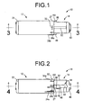
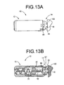
- FIGS. 1 to 5 depict a disposable lancing device (hereinafter termed simply “lancing device” for convenience) 10 according to one embodiment of the present invention.
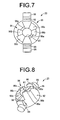
- the lancing device 10 is furnished with a housing 16 assembled from an operating member 12 and a pressing member 14; a lancet 18 and a protective cap 20 are housed in this housing 16.
- front refers to the right side in FIG 1
- back refers to the left side in FIG. 1
- axial direction refers to the left-right direction in FIG. 1 .
- the operating member 12 is of bottomed, approximately round tubular shape.
- a mating hole 24 is formed extending through the center section of its base part 22 in the axial direction.
- a housing tube portion 26 that projects axially inward from the base part 22 has been integrally formed in the interior of the operating member 12.
- the mating hole 24 of the base part 22 opens into the back end part of this housing tube portion 26. Meanwhile, the front end part of the housing tube portion 26 opens into the operating member 12.
- a catch projection 28 that projects up from the inner circumferential face and extends in the circumferential direction.
- the edge face of this catch projection 28 on the axially inward side thereof defines a detent step face 29 that projects up from the inner circumferential face of the operating member 12.
- a pair of insertion grooves 30, 30 of slit shape situated in the peripheral wall section.
- This pair of slit-shaped insertion grooves 30, 30 extend in the axial direction of the housing tube portion 26 and lie open at the distal end of the housing tube portion 26.
- the housing tube portion 26 has thick-walled construction integral with the peripheral wall of the operating member 12.
- a pair of linking portions 31, 31 that integrally link the housing tube portion 26 with the peripheral wall of the operating member 12 are formed between the two in localized sections on the circumference.
- the direction of opposition of the pair of insertion grooves 30, 30 and the direction of opposition of the linking portions 31, 31 are both axis-perpendicular to the housing tube portion 26, as well as orthogonal to one another.
- a plurality of indicia 32, 34a, 34b, 34c defined by raised projections have been formed on the outside peripheral face of the operating member 12.
- an initial stage indicia 32 is disposed in proximity to the rim on the opening 27 side, and is intended to indicate the initial stage rotation position of the pressing member 14 with respect to the operating member 12, discussed later.
- a first indicia 34a, a second indicia 34b, and a third indicia 34c are provided for the purpose of selective setting of the degree of extension of a skin puncture needle 62, discussed later, and are defined by linear raised projections extending in the axial direction from the rim at the opening 27 side of the operating member 12.
- the first indicia 34a is composed of a single linear raised projection
- the second indicia 34b is composed of two linear raised projections
- the third indicia 34c is composed of three linear raised projections to distinguish them from one another.
- the linear raised projections have progressively greater length going from the first indicia 34a to the second indicia 34b and then to the third indicia 34c, providing a visual representation of the progressively greater settings of the degree of extension of the skin puncture needle 62.
- the initial stage indicia 32 and the first to third indicia 34a, 34b, 34c are disposed at approximately unchanging intervals in the circumferential direction of the operating member 12.
- a plurality of grooves 36, 38a, 38b, 38c have been formed on the inside peripheral face of the operating member 12.
- These grooves 36, 38a, 38b, 38c are all constituted by recesses which extend in the axial direction from the rim at the opening 27 side of the operating member 12.
- An initial stage mating groove 36 is located at the inside peripheral face of the initial stage indicia 32.
- a first guide groove 38a is located at the inside peripheral face of the first indicia 34a
- a second guide groove 38b is located at the inside peripheral face of the second indicia 34b
- a third guide groove 38c is located at the inside peripheral face of the third indicia 34c.
- the first to third guide grooves 38a -38c are approximately equal in axial length, and extend into proximity with the open end of the housing tube portion 26 inside the operating member 12.
- the initial stage mating groove 36 is shorter than the first to third guide grooves 38a -38c.
- the pressing member 14 is of bottomed, approximately round tubular shape.
- the outside diameter dimension of its tube wall permits it to be slipped inside the operating member 12.
- a puncture opening 42 is formed extending through the center section in a base part 40 of the pressing member 14.
- a pair of support grooves 44, 44 have been formed in the tube wall of the pressing member 14.
- Each support groove 44 is of slit form extending through the tube wall and leading in the axial direction from the end of the pressing member 14 on an opening 45 side thereof and into proximity with its base part 40.
- the width dimension of each support groove 44 varies in the medial section in the lengthwise direction.
- a sloping part 46 is provided in the lengthwise medial section of one of the side walls of each support groove 44, with the side lying towards the opening 45 from this sloping part 46 constituting a wide-width part 48, and the side lying towards the base part 40 from this sloping part 46 constituting a narrow-width part 50.
- the pair of support grooves 44, 44 have been formed at locations in opposition across the diameter of the tube wall of the pressing member 14.
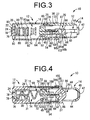
- the sloping parts 46, 46 of the pair of support grooves 44, 44 appear to overlap one another in side view of the pressing member 14 (see FIG. 2 ).
- a raised rib 52 has been formed on the outside peripheral face of the pressing member 14, and extends in the axial direction through the circumferential medial section of the pair of support grooves 44, 44. As discussed later, this rib 52, in cooperation with the indicia 32, 34a, 34b, 34c of the operating member 12, functions to indicate operational status of the lancing device 10.
- the pressing member 14 is provided at the end thereof on the opening side with a thick-walled part having large outside diameter dimension.
- the outside peripheral face of this thick-walled part constitutes a tapered face 53 of progressively smaller diameter towards the opening 45 side.
- the axial end face on the large-diameter side of the thick-walled part constitutes a locking step face 54 that projects up from the outside peripheral face of the pressing member 14.
- This tapered face 53 facilitates insertion of the pressing member 14 into the operating member 12. During insertion, once the tapered face 53 of the pressing member 14 has passed beyond the catch projection 28 of the operating member 12, the locking step face 54 of the pressing member 14 will become detained by the detent step face 29 of the operating member 12, thus preventing the pressing member 14 from becoming dislodged from the operating member 12.
- the lancet 18 includes a lancet hub 60 and the skin puncture needle 62.
- the lancet hub 60 is made of synthetic resin such as polypropylene, polyethylene, polycarbonate, ABS resin, or acrylic resin, and has a circular disk part 64 and a needle retention part 66 of cylindrical shape projected along the center axis of the circular disk part 64.
- a pair of abutting parts 68, 68 On the projecting face of the needle retention part 66 of the circular disk part 64, a pair of abutting parts 68, 68 have been integrally formed.
- the pair of abutting parts 68, 68 project out respectively in fan shapes which are symmetrical in the diametrical direction of the circular disk part 64.
- the basal section of the skin puncture needle 62 is secured to the needle retention part 66 of the lancet hub 60 through insert molding, adhesive bonding, or the like, and a needle tip 69 of the skin puncture needle 62 extends outwardly along the center axis of the lancet hub 60.
- a pair of outside peripheral walls 70, 70 have been formed in the outside peripheral section of the circular disk part 64, and are projected in the opposite axial direction from the needle retention part 66 of the circular disk part 64.
- a catch claw 72 has been formed on the outside peripheral face of each peripheral wall 70.
- the outside peripheral face of the catch claw 72 constitutes a tapered face 73 with progressively expanding diameter towards the direction of extension of the skin puncture needle 62.
- a spring member 74 has been integrally formed with the circular disk part 64.
- the spring member 74 is constituted by a plate spring made of resin having an accordion-like convoluted shape, one end of which has been linked to the circular disk part 64.
- the spring member 74 projects out from the circular disk part 64 in the opposite axial direction from the needle retention part 66.
- a mounting plate part 76 has been integrally formed at the other end of the spring member 74.
- a pair of mating claws 78, 78 are disposed on the mounting plate part 76, on the face thereof on the opposite side from the spring member 74.
- a plurality of insertion pins 80 that project out to both sides in the width direction have been formed on the spring member 74 and the mounting plate part 76. These insertion pins 80 have all been projected out on straight lines extending in the width direction of the spring member 74 and the mounting plate part 76 and intersecting the centerline of the circular disk part 64.
- the projecting dimension of the insertion pins 80 formed on the mounting plate part 76 is greater than the projecting dimension of the insertion pins 80 formed on the spring member 74.
- the insertion pins 80 have been arranged aligned on a straight line that extends along the direction of convolution of the spring member 74, through the medial sections which are situated between the peaks and valleys of the accordion-like convoluted shape of the spring member 74.
- the protective cap 20 is furnished with a cap body 86 of thick-walled, approximately round tubular shape (with approximately semispherical shape the inside diameter dimension of which is generally unchanging along the entire length, while the outside diameter dimension varies along an axis in the axial direction).
- a center hole of this cap body 86 defines a needle passage hole 87.
- the outside peripheral face of the cap body 86 becomes progressively smaller in diameter from first axial end towards the other axial end, producing a curved outside peripheral face of approximately semispherical shape.
- a pair of support shafts 88, 88 that project out in the axis-perpendicular direction have been integrally formed at the large-diameter end of the cap body 86.
- a needle storage hole 92 has been formed in the outside peripheral face of the cap body 86 in proximity to its large-diameter end, and extends in the orthogonal direction to the projecting direction of the pair of support shafts 88, 88, for a distance not far enough to reach the needle passage hole 87. That is, in the protective cap 20, the support shafts 88, 88, the needle passage hole 87, and the needle storage hole 92 extend in three different orthogonal directions.
- a stopper part 94 has been formed on the axial end face at the small-diameter end of the cap body 86.
- the stopper part 94 is defined by first to third stopper faces 96a, 96b, 96c that project in the axial direction of the cap body 86.
- These first to third stopper faces 96a, 96b, 96c are respectively formed by the distal end faces of a pair of fan-shaped projections situated in opposition in the diametrical direction of the cap body 86, viewed in the direction of the axis of the needle passage hole 87.
- the first to third stopper faces 96a, 96b, 96c are each constituted as fan shapes with a central angle of approximately 45°.
- the first to third stopper faces 96a, 96b, 96c differ from one another in their projected height outward in the axial direction of the cap body 86, with the first stopper face 96a, the second stopper face 96b, and the third stopper face 96c having progressively smaller projected dimensions, in that order.
- the pair of support shafts 88, 88 have outside diameter dimension permitting them to slide through the narrow-width part 50 of the support grooves 44, 44 of the pressing member 14.
- a projecting guide piece 98 is formed in a zone of the support shaft 88 lying towards the cap body 86 side and projects towards the stopper part 94 side of each support shaft 88.
- the projected height of the projecting guide pieces 98 has been established such that, with their direction of projection aligned with the widthwise direction of the support grooves 44 of the pressing member 14, it is possible for the support shafts 88 insert into the wide-width part 48 of the support grooves 44, but not to insert into the narrow-width part 50.
- the protective cap 20 may be integrally molded with the lancet 18 through an insert molding process using a mold cavity in which the skin puncture needle 62 has been arranged. By so doing, the needle tip 69 of the skin puncture needle 62 will be protected by the protective cap 20, and the needle storage hole 92 discussed earlier will be formed in the protective cap 20.
- a lancet structure 99 constituted by attaching the skin puncture needle 62 to the needle retention part 66 of the lancet 18 is slipped into the housing tube portion 26 of the operating member 12, and the mating claws 78 are mated with the mating hole 24 of the operating member 12.
- the lancet structure 99 is thereby attached to the operating member 12 with the mounting plate part 76 secured juxtaposed against the inside face of the base part 22 of the operating member 12.
- the insertion pins 80 which have been projected from the spring member 74 are passed through the insertion grooves 30 of the housing tube portion 26. This arrangement permits extensional and contractive elastic deformation of the spring member 74 while preventing it from tilting so as to more consistently produce the intended elastic deformation.
- the protective cap 20 may be integrally formed with the lancet 18 by insert molding as described above, or formed separately from the lancet 18. In the latter instance, installation of the protective cap 20 onto the skin puncture needle 62 may be carried out prior to attachment of the lancet structure 99 to the operating member 12, or after attachment. During installation of the protective cap 20 onto the skin puncture needle 62, in order to maintain the sterile conditions discussed later, it is preferable to slip it on until the distal end of the needle retention part 66 which retains the skin puncture needle 62 inserts into the needle storage hole 92 of the protective cap 20.
- the pressing member 14 is then attached to the operating member 12 by being fitted therein through the opening. During this process, the support shafts 88 of the protective cap 20 will intrude into the support grooves 44 of the pressing member 14. The pressing member 14 is then pushed into the operating member 12 until the tapered face 53 of the pressing member 14 is positioned axially to the back of the detent step face 29 of the operating member 12. By so doing, the locking step face 54 of the pressing member 14 will become locked by the detent step face 29, and the pressing member 14 will be attached in a condition of being positioned concentrically with the operating member 12 and fitting therein nondetachably.
- the lancet structure 99 and the protective cap 20 are housed inside the housing 16 of the lancing device 10 which has been assembled in this way.
- the needle tip 69 of the skin puncture needle 62 will face towards the base part 40 of the pressing member 14, while the spring member 74 will be positioned between the lancet 18 and the base part 22 of the operating member 12.
- the lancing device 10 then undergoes treatment so that at a minimum the needle tip 69 of the skin puncture needle 62 and the cap body 86 protecting it are placed in a sterile condition.
- the skin puncture needle 62 may be subjected to a sterilization process through radiation, high-pressure steam sterilization, or the like.
- the needle tip 69 of the skin puncture needle 62 can be kept in a sterile condition.
- the operating member 12 and the pressing member 14 are assembled rotatably with respect to one another about a common center axis.
- the lancing device 10 is provided to the user in an initial condition with the rib 52 of the pressing member 14 positioned aligned with the initial stage indicia 32 in the circumferential direction of the operating member 12, and mated with the initial stage mating groove 36.
- the protective cap 20 is accommodated with the support shafts 88 and the projecting guide pieces 98 inserted into the wide-width part 48 of the support grooves 44 of the pressing member 14, and with the projection direction of the projecting guide pieces 98 oriented in a direction orthogonal (the vertical direction in FIG. 2 ) to the direction of extension of the support grooves 44.
- the projecting guide pieces 98 are positioned within the wide-width part 48 with their projecting distal edge lying towards the sloping part 46 side from the support shaft 88.
- the protective cap 20 will be positioned with the needle storage hole 92 situated to the skin puncture needle 62 side with respect to the support shafts 88 and extending along the center axis of the pressing member 14.
- the section of the skin puncture needle 62 that projects out from the needle retention part 66 has been inserted into the needle storage hole 92 so that the needle tip 69 is protected by the protective cap 20 by virtue of being positioned inside the needle storage hole 92.
- the pressing member 14 is rotated about the center axis with respect to the operating member 12 until the rib 52 is aligned with a desired indicia selected from the first to third indicia 34a, 34b, 34c, so that the rib 52 mates with one of the first to third guide grooves 38a, 38b, 38c.
- the rib 52 is depicted as being aligned with the second indicia 34b and mating with the second guide groove 38b.
- the protective cap 20, together with the pressing member 14, rotate about the center axis with respect to the lancet 18. Because the first to third guide grooves 38a, 38b, 38c extend further towards the back in the axial direction of the operating member 12 than does the initial stage mating groove 36 which has been formed at the location of the initial stage indicia 32, with the rib 52 mated with any of the first to third guide grooves 38a, 38b, 38c, the operating member 12 will be permitted to undergo relative displacement in the axial direction with respect to the pressing member 14.
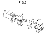
- the base part 40 of the pressing member 14 is pressed against a skin surface 100 at the collection site (depicted in model form) while pushing the operating member 12 towards the pressing member 14 in the axial direction.
- the protective cap 20 will be subjected to pushing force from the operating member 12 by virtue of being in abutment with a rim face 102 of the operating member 12, and will travel towards the front in the axial direction of the pressing member 14.
- the catch claw 72 is maintained in the locked state with respect to the axial back edge of the pressing member 14.
- the protective cap 20 thereby travels forward in the direction of extension of the skin puncture needle 62 with respect to the lancet 18, causing it to separate from the skin puncture needle 62 and causing the spring member 74 to begin to experience compressive deformation.
- the support shafts 88 and the projecting guide pieces 98 will rotate about the center axis of the support shafts 88 so as to intrude into the narrow-width part 50, causing the protective cap 20 to rotate by approximately 90° (in FIGS. 9A and 9B , counterclockwise rotation) about the support shafts 88.
- the needle passage hole 87 will thereby be positioned with its axial direction aligned with the skin puncture needle 62 extension path, while the protective cap 20 will be supported by the pressing member 14 at a location off the skin puncture needle 62 extension path, by virtue of the protective cap 20 being penetrated by the needle passage hole 87 on the skin puncture needle 62 extension path.
- the stopper part 94 will be positioned facing the abutting parts 68 of the lancet 18 in the direction of displacement of the lancet 18.
- the abutting parts 68 of the lancet 18 are generally identical in shape to the respective first to third stopper faces 96a, 96b, 96c of the protective cap 20 so as to be positioned in opposition thereto according to the rotational position of the pressing member 14 with respect to the operating member 12. Specifically, with the rib 52 at the position aligned with the first indicia 34a and mated with the first guide groove 38a, the abutting parts 68 of the lancet 18 will be positioned facing the first stopper face 96a in the direction of extension of the skin puncture needle 62.
- the first to third stopper faces 96a, 96b, 96c are situated progressively smaller distances away from the abutting parts 68 in the direction of extension of the skin puncture needle 62.
- the distance from the lancet 18 will be smallest when the first stopper face 96a, which has the greatest degree of projection, is positioned facing the abutting parts 68, while the distance from the lancet 18 will be greatest when the third stopper face 96c, which has the smallest degree of projection, is positioned facing the abutting parts 68.
- the pressing member 14 will travel farther towards the back in the axial direction of the operating member 12, whereby with the tapered face 73 of the lancet 18 guided by the linking portions 31 of the operating member 12, the catch claw 72 formation zone in the lancet 18 will undergo deformation in the diameter constriction direction.
- the catch claw 72 of the lancet 18 and the axial back end face of the pressing member 14 will be released from the locked state thereby, the lancet 18 will travel towards the base part 40 of the pressing member 14 due to the elastic recovery force of the spring member 74, and the skin puncture needle 62 will travel forward in the axial direction on the center axis of the housing 16.
- the spring member 74 will momentarily extend beyond its free length through elastic recovery force, and the lancet 18, which was previously urged by the spring member 74, will now be arrested from further forward travel in the axial direction by virtue of the abutting parts 68 coming into abutment against the first, second, or third stopper faces 96a, 96b, 96c, depending on which of these faces they have been positioned facing in the direction of extension of the skin puncture needle 62.
- the needle tip 69 will thereby be extended out to a prescribed degree from the housing 16 through the needle passage hole 87 of the protective cap 20 and the puncture opening 42 of the pressing member 14, so as to puncture the skin surface 100.
- the degree of extension of the skin puncture needle 62 out from the housing 16, which is regulated by the position of the forward traveling end of the lancet 18, will be established according to the degree of projection of the first to third stopper faces 96a, 96b, 96c, which in the present embodiment is smallest when abutting the first stopper face 96a and greatest when abutting the third stopper face 96c.
- the degree of extension will be greater than when abutting the first stopper face 96a, but less than when abutting the third stopper face 96c.
- the protective cap 20 with the stopper part 94, a protective mechanism for the skin puncture needle 62 and a mechanism for adjusting the degree of extension of the skin puncture needle 62 can be realized through a simple design having few parts. Thus, reduced production costs and smaller size of the lancing device 10 can be achieved.
- the support shafts 88 and the projecting guide pieces 98 which have been provided to the protective cap 20, the rim face 102 of the operating member 12, the support grooves 44 and sloping parts 46 which have been provided to the pressing member 14 together make up an interlock mechanism adapted to separate the protective cap 20 from the skin puncture needle 62 and position the stopper part 94 in opposition to the lancet 18 in the direction of extension of the skin puncture needle 62, whereby it is possible for these two operations to be carried out automatically through a single operation of pressing the operating member 12 against the skin surface 100, so that better ease of operation can be achieved.
- the degree of extension of the skin puncture needle 62 is adjusted stepwise so that this degree of extension can be set with consistently good accuracy, and enhanced safety may be attained as well. Further, adjustment of the degree of extension of the skin puncture needle 62 is possible through the simple operation of rotating the pressing member 14 with respect to the operating member 12.
- the stopper part 94 of the protective cap 20 has been designed with a stepped face profile, but in an alternative arrangement, the stopper part 94 will be identical in shape to the abutting parts 68 which have been formed on the lancet hub 60, while the abutting parts 68 on the lancet hub 60 will instead be given a stepped face profile similar to the stopper part 94.
- the number of steps may be established appropriately and may be greater or less than the number taught in the preceding embodiment.
- the protective cap 20 to move forward and backward steplessly in the direction of extension of the skin puncture needle 62 through screw adjustment for example, it will be possible for the degree of extension of the skin puncture needle 62 to be adjusted steplessly.
- the lancet hub 60 and the spring member 74 have been integrally formed, but it would be possible to form them separately, and to employ as the spring member a plate spring or coil spring of metal or the like. Also, while in the preceding embodiment the spring member 74 has been secured to the operating member 12, it is not essential that the spring member be secured to the operating member 12.
Landscapes
- Health & Medical Sciences (AREA)
- Life Sciences & Earth Sciences (AREA)
- Heart & Thoracic Surgery (AREA)
- Surgery (AREA)
- Biophysics (AREA)
- Pathology (AREA)
- Engineering & Computer Science (AREA)
- Biomedical Technology (AREA)
- Hematology (AREA)
- Medical Informatics (AREA)
- Molecular Biology (AREA)
- Physics & Mathematics (AREA)
- Animal Behavior & Ethology (AREA)
- General Health & Medical Sciences (AREA)
- Public Health (AREA)
- Veterinary Medicine (AREA)
- Dermatology (AREA)
- Measurement Of The Respiration, Hearing Ability, Form, And Blood Characteristics Of Living Organisms (AREA)
- Infusion, Injection, And Reservoir Apparatuses (AREA)
Claims (10)
- Einweg-Stechvorrichtung (10), bei welcher ein Federelement (74) und eine Lanzette (18) mit einer Hautpunktierungsnadel (62) innerhalb eines Gehäuses (16) derart untergebracht sind, dass eine Nadelspitze (69) der Hautpunktierungsnadel (62) dazu ausgestaltet ist, unter Drängen der Lanzette (18) durch das Federelement (74) aus dem Gehäuse (16) vorzuspringen, um eine Hautpunktierungsprozedur durchzuführen, wobei die Einweg-Stechvorrichtung (10) dadurch gekennzeichnet ist, dass:eine Schutzkappe (20), welche ein Nadeldurchgangsloch (87) aufweist und die Nadelspitze (69) der Hautpunktierungsnadel (62) bedeckt, dazu ausgestaltet ist, sich von der Hautpunktierungsnadel (62) zu separieren und zu rotieren, so dass das Nadeldurchgangsloch (87) der Schutzkappe (20) an einem Vorspringpfad der Hautpunktierungsnadel (62) positioniert ist, und die Hautpunktierungsprozedur mit der Schutzkappe (20) an dem Gehäuse (16) gehalten durchgeführt wird.
- Einweg-Stechvorrichtung (10) nach Anspruch 1, wobei die Schutzkappe (20) einen Kappenkörper (86), in welchem das Nadeldurchgangsloch (87) vorgesehen ist, und Halteschäfte (88), welche an dem Kappenkörper (86) vorgesehen sind und sich senkrecht zu einer Durchgangsrichtung des Nadeldurchgangslochs (87) erstrecken, aufweist; während das Gehäuse (16) mit Halterillen (44) versehen ist, welche sich in einer Erstreckungsrichtung der Hautpunktierungsnadel (62) erstrecken, wobei die Halteschäfte (88) der Schutzkappe (20) in den Halterillen (44) des Gehäuses(16) gehalten sind.
- Einweg-Stechvorrichtung (10) nach Anspruch 2, wobei jeder der Halteschäfte (88) der Schutzkappe (20) mit einem hervorstehenden Führungsteil (98) versehen ist, welches sich in der Durchgangsrichtung des Nadeldurchganglochs (87) erstreckt; wobei jede der Halterrillen (44) des Gehäuses (16) einen Teil mit großer Breite (48), einen Teil mit geringer Breite (50) und einen Neigungsteil (46), welcher den Teil mit großer Breite (48) mit dem Teil mit geringer Breite (50) verbindet, aufweist; und die Schutzkappe (20) dazu ausgestaltet ist, rotiert zu werden durch Verschieben der hervorstehenden Führungsteile (98) in die Halterrillen (44) und deren Bewegen von einem Ende mit großer Breite in Richtung eines Endes mit geringer Breite.
- Einweg-Stechvorrichtung (10) nach einem der Ansprüche 1-3, wobei während der Hautpunktierungsprozedur die von der Hautpunktierungsnadel (62) separierte Schutzkappe (20) einen Stopperteil (94) definiert, an welchem die Lanzette (18) in Anschlag kommt; und ein Grad des Vorspringens der Hautpunktierungsnadel (62) über das Gehäuse (16) hinaus einstellbar ist durch Modifikation einer Position eines sich bewegenden Endes der Lanzette (18) in einer Vorspringrichtung der Hautpunktierungsnadel (62), welche reguliert wird durch Anschlag der Lanzette (18) gegen das Stopperteil (94).
- Einweg-Stechvorrichtung (10) nach einem der Ansprüche 1-4, wobei das Gehäuse (16) ein Druckelement (14), welches dazu ausgestaltet ist, gegen eine Hautoberfläche (100) an einer Blutentnahmestelle gedrückt zu werden, und ein Betätigungselement (12), welches beweglich mit dem Druckelement (14) verbunden ist, beinhaltet; und das Betätigungselement (12) beweglich ist, um einen verriegelten Zustand der Lanzette (18) zu lösen, welche durch das Federelement (74) bezüglich des Druckelements (14) gedrängt wird, so dass die Hautpunktierungsnadel (62) aus dem Druckelement (14) vorspringt, um die Hautpunktierungsprozedur durchzuführen.
- Einweg-Stechvorrichtung (10) nach Anspruch 5, wobei sowohl das Druckelement (14) als auch das Betätigungselement (12) von röhrenartiger Form mit Boden sind und mit ihren Öffnungen zusammenpassend ausgerichtet sind und zusammengefügt sind, so dass sie zu einer relativen Bewegung in einer axialen Richtung in der Lage sind, um eine hohle Struktur für das Gehäuse (16) zu ergeben; die Lanzette (18) in dem Gehäuse (16) untergebracht ist, so dass sie in dessen axialer Richtung beweglich ist, wobei die Hautpunktierungsnadel (62) der Lanzette (18) in Richtung eines Basisteils (40) des Druckelements (14) hervorsteht und wobei eine Punktierungsöffnung (62) in dem Basisteil des Druckselements (14) ausgebildet ist; die Schutzkappe (20) dazu ausgestaltet ist, sich von der Hautpunktierungsnadel (62) zu separieren und durch einen Schiebevorgang des Betätigungselements (12) gegen das Druckelement (14) zu rotieren, wobei der Basisteil (40) des Druckelements (14) gegen die Hautoberfläche (100) an der Blutentnahmestelle gedrückt wird; und die Hautpunktierungsprozedur durchgeführt wird, indem die Lanzette (18) aus dem verriegelten Zustand bezüglich des Druckelements (14) gelöst wird, woraufhin die Lanzette (18) sich unter einer drängenden Kraft des Federelements (74), welches sich zwischen dem Gehäuse (16) und der Lanzette (18) befindet, in Richtung des Basisteils (40) des Druckelements (14) bewegt, was bewirkt, dass die Nadelspitze (69) der Hautpunktierungsnadel (62) durch die Punktierungsöffnung (42) des Druckelements (14) nach außen vorspringt, um die Hautpunktierungsprozedur durchzuführen.
- Einweg-Stechvorrichtung (10) nach Anspruch 5 oder 6, wobei das Betätigungselement (12) mit einem Sicherheitsverriegelungsmechanismus (36,52) ausgestattet ist, welcher dazu ausgestaltet ist, einen Vorgang zum Lösen des verriegelten Zustands der durch das Federelement (74) bezüglich des Druckelements (14) gedrängten Lanzette (18) zu arretieren.
- Einweg-Stechvorrichtung (10) nach einem der Ansprüche 5-7, wobei, wenn die Schutzkappe (20), welche von dem Druckelement (14) gehalten wird, und die Lanzette (18), welche von dem Betätigungselement (12) gehalten wird, eine relative Drehung durch eine koaxiale relative Drehung des Druckelements (14) bezüglich des Betätigungsfelds (12) erfahren, eine Position, an welcher die Lanzette (18) mit dem an der Schutzkappe (20) ausgebildeten Stopperteil (94) in Anschlag kommt, sich ändert, um eine damit verbundene Änderung in einer Position eines sich bewegenden Endes der Lanzette (18) hervorzurufen, welche durch des Anschlag an dem Stopperteil (94) reguliert wird.
- Einweg-Stechvorrichtung (10) nach einem der Ansprüche 4-8, wobei eine Position einer Anschlagfläche des Stopperteils (94), an welchem die Lanzette (18) in Anschlag kommt, in der Vorspringrichtung der Hautpunktierungsnadel (62) veränderbar ist.
- Einweg-Stechvorrichtung (10) der Ansprüche 5-9, wobei ein Sperrenmechanismus (44, 46, 88, 98, 102) vorgesehen ist, wodurch eine während der Hautpunktierungsprozedur auf das Betätigungselement (12) ausgeübte Betätigungskraft auf die Schutzkappe (20) übertragen wird, so dass veranlasst wird, dass sich die Schutzkappe (20) von der Hautpunktierungsnadel (62) separiert und zu einer Position zum Bilden des Stopperteils (94) geführt wird.
Applications Claiming Priority (2)
| Application Number | Priority Date | Filing Date | Title |
|---|---|---|---|
| JP2009080544A JP5488868B2 (ja) | 2009-03-27 | 2009-03-27 | ディスポーザブル型採血器具 |
| JP2009080474A JP5267870B2 (ja) | 2009-03-27 | 2009-03-27 | ディスポーザブル型採血器具 |
Publications (2)
| Publication Number | Publication Date |
|---|---|
| EP2233076A1 EP2233076A1 (de) | 2010-09-29 |
| EP2233076B1 true EP2233076B1 (de) | 2012-01-25 |
Family
ID=42270305
Family Applications (1)
| Application Number | Title | Priority Date | Filing Date |
|---|---|---|---|
| EP10002823A Not-in-force EP2233076B1 (de) | 2009-03-27 | 2010-03-17 | Einweg-Stechvorrichtung |
Country Status (4)
| Country | Link |
|---|---|
| US (1) | US8262685B2 (de) |
| EP (1) | EP2233076B1 (de) |
| CN (1) | CN101843493B (de) |
| AT (1) | ATE542477T1 (de) |
Families Citing this family (4)
| Publication number | Priority date | Publication date | Assignee | Title |
|---|---|---|---|---|
| JP5540617B2 (ja) * | 2009-09-10 | 2014-07-02 | ニプロ株式会社 | ディスポーザブル型採血器具 |
| CN102309331B (zh) * | 2011-09-02 | 2013-04-17 | 苏州乔阳医学科技有限公司 | 前压式一次性安全采血针 |
| US10646150B2 (en) * | 2013-03-12 | 2020-05-12 | Ascensia Diabetes Care Holdings Ag | Lancing device |
| CN113317849B (zh) * | 2021-04-22 | 2022-09-27 | 卫飞 | 一种骨穿刺针发射装置 |
Family Cites Families (24)
| Publication number | Priority date | Publication date | Assignee | Title |
|---|---|---|---|---|
| US489547A (en) * | 1893-01-10 | shipley | ||
| SE422150B (sv) * | 1980-04-23 | 1982-02-22 | Enstroem Hans | Anordning for genomstickning av hud samt sett att framstella en sadan anordning |
| US4616649A (en) | 1984-09-20 | 1986-10-14 | Becton, Dickinson And Company | Lancet |
| GB8710470D0 (en) | 1987-05-01 | 1987-06-03 | Mumford Ltd Owen | Blood sampling devices |
| US4895147A (en) | 1988-10-28 | 1990-01-23 | Sherwood Medical Company | Lancet injector |
| DE69229180T2 (de) | 1991-11-12 | 1999-10-14 | Urs. A. Ramel | Lanzetteneinrichtung |
| JP2561697Y2 (ja) * | 1992-08-28 | 1998-02-04 | アプルス株式会社 | ランセット |
| CA2079192C (en) * | 1992-09-25 | 1995-12-26 | Bernard Strong | Combined lancet and multi-function cap and lancet injector for use therewith |
| DE19718081A1 (de) | 1997-04-29 | 1998-11-05 | Boehringer Mannheim Gmbh | Einweg Blutlanzette |
| US6053930A (en) * | 1998-05-11 | 2000-04-25 | Ruppert; Norbert | Single use lancet assembly |
| GB9928876D0 (en) * | 1999-12-08 | 2000-02-02 | Owen Mumford Ltd | Improvements relating to combined lancets and caps |
| JP4299667B2 (ja) * | 2001-10-31 | 2009-07-22 | アークレイ株式会社 | 穿刺装置 |
| DE10222235A1 (de) | 2002-05-16 | 2003-11-27 | Roche Diagnostics Gmbh | Blutentnahmesystem |
| PL207804B1 (pl) | 2003-07-29 | 2011-02-28 | Htl Strefa Społka Z Ograniczoną Odpowiedzialnością | Przyrząd do nakłuwania |
| US7223248B2 (en) * | 2003-08-13 | 2007-05-29 | Lifescan, Inc. | Packaged medical device with a deployable dermal tissue penetration member |
| US20050143771A1 (en) * | 2003-12-02 | 2005-06-30 | Stout Jeffrey T. | Lancing device with combination depth and activation control |
| PL1755456T3 (pl) | 2004-05-07 | 2010-03-31 | Becton Dickinson Co | Urządzenie lancetowe uruchamiane przez przyłożenie |
| US9380975B2 (en) | 2004-05-07 | 2016-07-05 | Becton, Dickinson And Company | Contact activated lancet device |
| EP1747756A4 (de) * | 2004-05-17 | 2010-08-04 | Izumi Cosmo Co Ltd | Lanzettenanordnung |
| US7879059B2 (en) | 2004-10-06 | 2011-02-01 | Izumi-Cosmo Company, Limited | Lancet assembly |
| EP1772099B8 (de) * | 2005-10-08 | 2011-10-05 | Roche Diagnostics GmbH | Stechsystem |
| WO2007069572A1 (ja) * | 2005-12-12 | 2007-06-21 | Nichinan Corporation | 穿刺針装置 |
| CN200945164Y (zh) * | 2006-08-14 | 2007-09-12 | 施国平 | 一次性可调穿刺深度安全采血针 |
| CN201098127Y (zh) * | 2007-10-26 | 2008-08-13 | 黄秋月 | 安全采血针 |
-
2010
- 2010-03-15 US US12/659,625 patent/US8262685B2/en not_active Expired - Fee Related
- 2010-03-17 AT AT10002823T patent/ATE542477T1/de active
- 2010-03-17 EP EP10002823A patent/EP2233076B1/de not_active Not-in-force
- 2010-03-24 CN CN2010101407553A patent/CN101843493B/zh not_active Expired - Fee Related
Also Published As
| Publication number | Publication date |
|---|---|
| US8262685B2 (en) | 2012-09-11 |
| ATE542477T1 (de) | 2012-02-15 |
| CN101843493A (zh) | 2010-09-29 |
| US20100249819A1 (en) | 2010-09-30 |
| EP2233076A1 (de) | 2010-09-29 |
| CN101843493B (zh) | 2013-11-06 |
Similar Documents
| Publication | Publication Date | Title |
|---|---|---|
| AU2016213847B2 (en) | Safety needle assembly | |
| EP2279773B1 (de) | Katheterhaltewerkzeug | |
| ES2959595T3 (es) | Conjuntos de aguja de seguridad y métodos relacionados | |
| JP5514008B2 (ja) | ディスポーザブル型穿刺器具 | |
| AU2013249933B2 (en) | A lancet | |
| EP2233076B1 (de) | Einweg-Stechvorrichtung | |
| JP6919795B2 (ja) | 針組立体 | |
| KR101716529B1 (ko) | 일회용 채혈 기구 | |
| BR112019024921A2 (pt) | Dispositivo médico aprimorado com agulha de segurança de retração resiliente | |
| JP2005312763A (ja) | 穿刺針カートリッジ、穿刺器具、先端ユニットおよびアダプタ | |
| JP5267870B2 (ja) | ディスポーザブル型採血器具 | |
| JP7001065B2 (ja) | ディスポーザブル型穿刺器具 | |
| JP5488868B2 (ja) | ディスポーザブル型採血器具 | |
| JP6676899B2 (ja) | 穿刺器具 | |
| JP6369127B2 (ja) | 穿刺器具 | |
| TWI838553B (zh) | 留置針組裝體 | |
| KR20240163081A (ko) | 삽입 장치, 삽입 시스템 및 의료 장치를 삽입하기 위한 방법 | |
| JP2024144684A (ja) | 針組立体 | |
| JP5686215B2 (ja) | ディスポーザブル型穿刺器具 | |
| JP2006081751A (ja) | 針プロテクター付きランセット及びこれを装着する穿刺具 |
Legal Events
| Date | Code | Title | Description |
|---|---|---|---|
| PUAI | Public reference made under article 153(3) epc to a published international application that has entered the european phase |
Free format text: ORIGINAL CODE: 0009012 |
|
| AK | Designated contracting states |
Kind code of ref document: A1 Designated state(s): AT BE BG CH CY CZ DE DK EE ES FI FR GB GR HR HU IE IS IT LI LT LU LV MC MK MT NL NO PL PT RO SE SI SK SM TR |
|
| AX | Request for extension of the european patent |
Extension state: AL BA ME RS |
|
| 17P | Request for examination filed |
Effective date: 20101112 |
|
| GRAP | Despatch of communication of intention to grant a patent |
Free format text: ORIGINAL CODE: EPIDOSNIGR1 |
|
| RIC1 | Information provided on ipc code assigned before grant |
Ipc: A61B 5/151 20060101AFI20110428BHEP |
|
| GRAS | Grant fee paid |
Free format text: ORIGINAL CODE: EPIDOSNIGR3 |
|
| GRAA | (expected) grant |
Free format text: ORIGINAL CODE: 0009210 |
|
| RAP1 | Party data changed (applicant data changed or rights of an application transferred) |
Owner name: NIPRO CORPORATION |
|
| AK | Designated contracting states |
Kind code of ref document: B1 Designated state(s): AT BE BG CH CY CZ DE DK EE ES FI FR GB GR HR HU IE IS IT LI LT LU LV MC MK MT NL NO PL PT RO SE SI SK SM TR |
|
| REG | Reference to a national code |
Ref country code: GB Ref legal event code: FG4D |
|
| REG | Reference to a national code |
Ref country code: CH Ref legal event code: EP |
|
| REG | Reference to a national code |
Ref country code: AT Ref legal event code: REF Ref document number: 542477 Country of ref document: AT Kind code of ref document: T Effective date: 20120215 |
|
| REG | Reference to a national code |
Ref country code: IE Ref legal event code: FG4D |
|
| REG | Reference to a national code |
Ref country code: DE Ref legal event code: R096 Ref document number: 602010000706 Country of ref document: DE Effective date: 20120329 |
|
| REG | Reference to a national code |
Ref country code: NL Ref legal event code: VDEP Effective date: 20120125 |
|
| LTIE | Lt: invalidation of european patent or patent extension |
Effective date: 20120125 |
|
| PG25 | Lapsed in a contracting state [announced via postgrant information from national office to epo] |
Ref country code: BE Free format text: LAPSE BECAUSE OF FAILURE TO SUBMIT A TRANSLATION OF THE DESCRIPTION OR TO PAY THE FEE WITHIN THE PRESCRIBED TIME-LIMIT Effective date: 20120125 Ref country code: HR Free format text: LAPSE BECAUSE OF FAILURE TO SUBMIT A TRANSLATION OF THE DESCRIPTION OR TO PAY THE FEE WITHIN THE PRESCRIBED TIME-LIMIT Effective date: 20120125 Ref country code: NO Free format text: LAPSE BECAUSE OF FAILURE TO SUBMIT A TRANSLATION OF THE DESCRIPTION OR TO PAY THE FEE WITHIN THE PRESCRIBED TIME-LIMIT Effective date: 20120425 Ref country code: BG Free format text: LAPSE BECAUSE OF FAILURE TO SUBMIT A TRANSLATION OF THE DESCRIPTION OR TO PAY THE FEE WITHIN THE PRESCRIBED TIME-LIMIT Effective date: 20120425 Ref country code: LT Free format text: LAPSE BECAUSE OF FAILURE TO SUBMIT A TRANSLATION OF THE DESCRIPTION OR TO PAY THE FEE WITHIN THE PRESCRIBED TIME-LIMIT Effective date: 20120125 Ref country code: IS Free format text: LAPSE BECAUSE OF FAILURE TO SUBMIT A TRANSLATION OF THE DESCRIPTION OR TO PAY THE FEE WITHIN THE PRESCRIBED TIME-LIMIT Effective date: 20120525 Ref country code: NL Free format text: LAPSE BECAUSE OF FAILURE TO SUBMIT A TRANSLATION OF THE DESCRIPTION OR TO PAY THE FEE WITHIN THE PRESCRIBED TIME-LIMIT Effective date: 20120125 |
|
| PG25 | Lapsed in a contracting state [announced via postgrant information from national office to epo] |
Ref country code: PT Free format text: LAPSE BECAUSE OF FAILURE TO SUBMIT A TRANSLATION OF THE DESCRIPTION OR TO PAY THE FEE WITHIN THE PRESCRIBED TIME-LIMIT Effective date: 20120525 Ref country code: LV Free format text: LAPSE BECAUSE OF FAILURE TO SUBMIT A TRANSLATION OF THE DESCRIPTION OR TO PAY THE FEE WITHIN THE PRESCRIBED TIME-LIMIT Effective date: 20120125 Ref country code: FI Free format text: LAPSE BECAUSE OF FAILURE TO SUBMIT A TRANSLATION OF THE DESCRIPTION OR TO PAY THE FEE WITHIN THE PRESCRIBED TIME-LIMIT Effective date: 20120125 Ref country code: PL Free format text: LAPSE BECAUSE OF FAILURE TO SUBMIT A TRANSLATION OF THE DESCRIPTION OR TO PAY THE FEE WITHIN THE PRESCRIBED TIME-LIMIT Effective date: 20120125 Ref country code: GR Free format text: LAPSE BECAUSE OF FAILURE TO SUBMIT A TRANSLATION OF THE DESCRIPTION OR TO PAY THE FEE WITHIN THE PRESCRIBED TIME-LIMIT Effective date: 20120426 |
|
| REG | Reference to a national code |
Ref country code: AT Ref legal event code: MK05 Ref document number: 542477 Country of ref document: AT Kind code of ref document: T Effective date: 20120125 |
|
| PG25 | Lapsed in a contracting state [announced via postgrant information from national office to epo] |
Ref country code: CY Free format text: LAPSE BECAUSE OF FAILURE TO SUBMIT A TRANSLATION OF THE DESCRIPTION OR TO PAY THE FEE WITHIN THE PRESCRIBED TIME-LIMIT Effective date: 20120125 |
|
| PG25 | Lapsed in a contracting state [announced via postgrant information from national office to epo] |
Ref country code: SE Free format text: LAPSE BECAUSE OF FAILURE TO SUBMIT A TRANSLATION OF THE DESCRIPTION OR TO PAY THE FEE WITHIN THE PRESCRIBED TIME-LIMIT Effective date: 20120125 Ref country code: SI Free format text: LAPSE BECAUSE OF FAILURE TO SUBMIT A TRANSLATION OF THE DESCRIPTION OR TO PAY THE FEE WITHIN THE PRESCRIBED TIME-LIMIT Effective date: 20120125 Ref country code: EE Free format text: LAPSE BECAUSE OF FAILURE TO SUBMIT A TRANSLATION OF THE DESCRIPTION OR TO PAY THE FEE WITHIN THE PRESCRIBED TIME-LIMIT Effective date: 20120125 Ref country code: RO Free format text: LAPSE BECAUSE OF FAILURE TO SUBMIT A TRANSLATION OF THE DESCRIPTION OR TO PAY THE FEE WITHIN THE PRESCRIBED TIME-LIMIT Effective date: 20120125 Ref country code: CZ Free format text: LAPSE BECAUSE OF FAILURE TO SUBMIT A TRANSLATION OF THE DESCRIPTION OR TO PAY THE FEE WITHIN THE PRESCRIBED TIME-LIMIT Effective date: 20120125 Ref country code: MC Free format text: LAPSE BECAUSE OF NON-PAYMENT OF DUE FEES Effective date: 20120331 Ref country code: DK Free format text: LAPSE BECAUSE OF FAILURE TO SUBMIT A TRANSLATION OF THE DESCRIPTION OR TO PAY THE FEE WITHIN THE PRESCRIBED TIME-LIMIT Effective date: 20120125 |
|
| PG25 | Lapsed in a contracting state [announced via postgrant information from national office to epo] |
Ref country code: SK Free format text: LAPSE BECAUSE OF FAILURE TO SUBMIT A TRANSLATION OF THE DESCRIPTION OR TO PAY THE FEE WITHIN THE PRESCRIBED TIME-LIMIT Effective date: 20120125 |
|
| PLBE | No opposition filed within time limit |
Free format text: ORIGINAL CODE: 0009261 |
|
| STAA | Information on the status of an ep patent application or granted ep patent |
Free format text: STATUS: NO OPPOSITION FILED WITHIN TIME LIMIT |
|
| 26N | No opposition filed |
Effective date: 20121026 |
|
| REG | Reference to a national code |
Ref country code: IE Ref legal event code: MM4A |
|
| PG25 | Lapsed in a contracting state [announced via postgrant information from national office to epo] |
Ref country code: AT Free format text: LAPSE BECAUSE OF FAILURE TO SUBMIT A TRANSLATION OF THE DESCRIPTION OR TO PAY THE FEE WITHIN THE PRESCRIBED TIME-LIMIT Effective date: 20120125 Ref country code: IE Free format text: LAPSE BECAUSE OF NON-PAYMENT OF DUE FEES Effective date: 20120317 |
|
| REG | Reference to a national code |
Ref country code: DE Ref legal event code: R097 Ref document number: 602010000706 Country of ref document: DE Effective date: 20121026 |
|
| PG25 | Lapsed in a contracting state [announced via postgrant information from national office to epo] |
Ref country code: MK Free format text: LAPSE BECAUSE OF FAILURE TO SUBMIT A TRANSLATION OF THE DESCRIPTION OR TO PAY THE FEE WITHIN THE PRESCRIBED TIME-LIMIT Effective date: 20120125 |
|
| PG25 | Lapsed in a contracting state [announced via postgrant information from national office to epo] |
Ref country code: ES Free format text: LAPSE BECAUSE OF FAILURE TO SUBMIT A TRANSLATION OF THE DESCRIPTION OR TO PAY THE FEE WITHIN THE PRESCRIBED TIME-LIMIT Effective date: 20120506 |
|
| PG25 | Lapsed in a contracting state [announced via postgrant information from national office to epo] |
Ref country code: MT Free format text: LAPSE BECAUSE OF FAILURE TO SUBMIT A TRANSLATION OF THE DESCRIPTION OR TO PAY THE FEE WITHIN THE PRESCRIBED TIME-LIMIT Effective date: 20120125 |
|
| PG25 | Lapsed in a contracting state [announced via postgrant information from national office to epo] |
Ref country code: TR Free format text: LAPSE BECAUSE OF FAILURE TO SUBMIT A TRANSLATION OF THE DESCRIPTION OR TO PAY THE FEE WITHIN THE PRESCRIBED TIME-LIMIT Effective date: 20120125 |
|
| PG25 | Lapsed in a contracting state [announced via postgrant information from national office to epo] |
Ref country code: LU Free format text: LAPSE BECAUSE OF NON-PAYMENT OF DUE FEES Effective date: 20120317 Ref country code: SM Free format text: LAPSE BECAUSE OF FAILURE TO SUBMIT A TRANSLATION OF THE DESCRIPTION OR TO PAY THE FEE WITHIN THE PRESCRIBED TIME-LIMIT Effective date: 20120125 |
|
| PG25 | Lapsed in a contracting state [announced via postgrant information from national office to epo] |
Ref country code: HU Free format text: LAPSE BECAUSE OF FAILURE TO SUBMIT A TRANSLATION OF THE DESCRIPTION OR TO PAY THE FEE WITHIN THE PRESCRIBED TIME-LIMIT Effective date: 20100317 |
|
| REG | Reference to a national code |
Ref country code: CH Ref legal event code: PL |
|
| PG25 | Lapsed in a contracting state [announced via postgrant information from national office to epo] |
Ref country code: CH Free format text: LAPSE BECAUSE OF NON-PAYMENT OF DUE FEES Effective date: 20140331 Ref country code: LI Free format text: LAPSE BECAUSE OF NON-PAYMENT OF DUE FEES Effective date: 20140331 |
|
| REG | Reference to a national code |
Ref country code: FR Ref legal event code: PLFP Year of fee payment: 6 |
|
| REG | Reference to a national code |
Ref country code: FR Ref legal event code: PLFP Year of fee payment: 7 |
|
| REG | Reference to a national code |
Ref country code: FR Ref legal event code: PLFP Year of fee payment: 8 |
|
| REG | Reference to a national code |
Ref country code: FR Ref legal event code: PLFP Year of fee payment: 9 |
|
| PGFP | Annual fee paid to national office [announced via postgrant information from national office to epo] |
Ref country code: FR Payment date: 20190322 Year of fee payment: 10 Ref country code: GB Payment date: 20190320 Year of fee payment: 10 Ref country code: IT Payment date: 20190325 Year of fee payment: 10 Ref country code: DE Payment date: 20190321 Year of fee payment: 10 |
|
| REG | Reference to a national code |
Ref country code: DE Ref legal event code: R119 Ref document number: 602010000706 Country of ref document: DE |
|
| PG25 | Lapsed in a contracting state [announced via postgrant information from national office to epo] |
Ref country code: DE Free format text: LAPSE BECAUSE OF NON-PAYMENT OF DUE FEES Effective date: 20201001 Ref country code: FR Free format text: LAPSE BECAUSE OF NON-PAYMENT OF DUE FEES Effective date: 20200331 |
|
| GBPC | Gb: european patent ceased through non-payment of renewal fee |
Effective date: 20200317 |
|
| PG25 | Lapsed in a contracting state [announced via postgrant information from national office to epo] |
Ref country code: GB Free format text: LAPSE BECAUSE OF NON-PAYMENT OF DUE FEES Effective date: 20200317 |
|
| PG25 | Lapsed in a contracting state [announced via postgrant information from national office to epo] |
Ref country code: IT Free format text: LAPSE BECAUSE OF NON-PAYMENT OF DUE FEES Effective date: 20200317 |