EP2233095A1 - Vis pour osteosynthèse à pas multiples - Google Patents
Vis pour osteosynthèse à pas multiples Download PDFInfo
- Publication number
- EP2233095A1 EP2233095A1 EP10169737A EP10169737A EP2233095A1 EP 2233095 A1 EP2233095 A1 EP 2233095A1 EP 10169737 A EP10169737 A EP 10169737A EP 10169737 A EP10169737 A EP 10169737A EP 2233095 A1 EP2233095 A1 EP 2233095A1
- Authority
- EP
- European Patent Office
- Prior art keywords
- end portion
- threaded
- bone screw
- bone
- threaded section
- Prior art date
- Legal status (The legal status is an assumption and is not a legal conclusion. Google has not performed a legal analysis and makes no representation as to the accuracy of the status listed.)
- Withdrawn
Links
- 210000000988 bone and bone Anatomy 0.000 title claims abstract description 159
- 230000001054 cortical effect Effects 0.000 claims abstract description 18
- 238000004873 anchoring Methods 0.000 claims abstract description 15
- 239000007943 implant Substances 0.000 claims abstract description 13
- 230000008878 coupling Effects 0.000 claims abstract description 12
- 238000010168 coupling process Methods 0.000 claims abstract description 12
- 238000005859 coupling reaction Methods 0.000 claims abstract description 12
- 239000011295 pitch Substances 0.000 description 13
- 230000009977 dual effect Effects 0.000 description 8
- 238000000034 method Methods 0.000 description 8
- 230000007246 mechanism Effects 0.000 description 6
- 210000003710 cerebral cortex Anatomy 0.000 description 5
- 230000008901 benefit Effects 0.000 description 4
- 230000007423 decrease Effects 0.000 description 3
- -1 for example Substances 0.000 description 2
- 239000000463 material Substances 0.000 description 2
- 230000004048 modification Effects 0.000 description 2
- 238000012986 modification Methods 0.000 description 2
- 241000168096 Glareolidae Species 0.000 description 1
- 229910001069 Ti alloy Inorganic materials 0.000 description 1
- RTAQQCXQSZGOHL-UHFFFAOYSA-N Titanium Chemical compound [Ti] RTAQQCXQSZGOHL-UHFFFAOYSA-N 0.000 description 1
- 230000004075 alteration Effects 0.000 description 1
- 239000011324 bead Substances 0.000 description 1
- 239000000560 biocompatible material Substances 0.000 description 1
- 239000002639 bone cement Substances 0.000 description 1
- 238000002513 implantation Methods 0.000 description 1
- 210000004705 lumbosacral region Anatomy 0.000 description 1
- 229910001092 metal group alloy Inorganic materials 0.000 description 1
- 230000001737 promoting effect Effects 0.000 description 1
- 230000009467 reduction Effects 0.000 description 1
- 238000010079 rubber tapping Methods 0.000 description 1
- 239000010935 stainless steel Substances 0.000 description 1
- 229910001220 stainless steel Inorganic materials 0.000 description 1
- 210000000115 thoracic cavity Anatomy 0.000 description 1
- 229910052719 titanium Inorganic materials 0.000 description 1
- 239000010936 titanium Substances 0.000 description 1
Images


Classifications
-
- A—HUMAN NECESSITIES
- A61—MEDICAL OR VETERINARY SCIENCE; HYGIENE
- A61B—DIAGNOSIS; SURGERY; IDENTIFICATION
- A61B17/00—Surgical instruments, devices or methods
- A61B17/56—Surgical instruments or methods for treatment of bones or joints; Devices specially adapted therefor
- A61B17/58—Surgical instruments or methods for treatment of bones or joints; Devices specially adapted therefor for osteosynthesis, e.g. bone plates, screws or setting implements
- A61B17/68—Internal fixation devices, including fasteners and spinal fixators, even if a part thereof projects from the skin
- A61B17/84—Fasteners therefor or fasteners being internal fixation devices
- A61B17/86—Pins or screws or threaded wires; nuts therefor
- A61B17/8625—Shanks, i.e. parts contacting bone tissue
- A61B17/863—Shanks, i.e. parts contacting bone tissue with thread interrupted or changing its form along shank, other than constant taper
-
- A—HUMAN NECESSITIES
- A61—MEDICAL OR VETERINARY SCIENCE; HYGIENE
- A61B—DIAGNOSIS; SURGERY; IDENTIFICATION
- A61B17/00—Surgical instruments, devices or methods
- A61B17/56—Surgical instruments or methods for treatment of bones or joints; Devices specially adapted therefor
- A61B17/58—Surgical instruments or methods for treatment of bones or joints; Devices specially adapted therefor for osteosynthesis, e.g. bone plates, screws or setting implements
- A61B17/68—Internal fixation devices, including fasteners and spinal fixators, even if a part thereof projects from the skin
- A61B17/70—Spinal positioners or stabilisers, e.g. stabilisers comprising fluid filler in an implant
- A61B17/7001—Screws or hooks combined with longitudinal elements which do not contact vertebrae
- A61B17/7032—Screws or hooks with U-shaped head or back through which longitudinal rods pass
-
- A—HUMAN NECESSITIES
- A61—MEDICAL OR VETERINARY SCIENCE; HYGIENE
- A61B—DIAGNOSIS; SURGERY; IDENTIFICATION
- A61B17/00—Surgical instruments, devices or methods
- A61B17/56—Surgical instruments or methods for treatment of bones or joints; Devices specially adapted therefor
- A61B17/58—Surgical instruments or methods for treatment of bones or joints; Devices specially adapted therefor for osteosynthesis, e.g. bone plates, screws or setting implements
- A61B17/68—Internal fixation devices, including fasteners and spinal fixators, even if a part thereof projects from the skin
- A61B17/70—Spinal positioners or stabilisers, e.g. stabilisers comprising fluid filler in an implant
- A61B17/7001—Screws or hooks combined with longitudinal elements which do not contact vertebrae
- A61B17/7035—Screws or hooks, wherein a rod-clamping part and a bone-anchoring part can pivot relative to each other
- A61B17/7037—Screws or hooks, wherein a rod-clamping part and a bone-anchoring part can pivot relative to each other wherein pivoting is blocked when the rod is clamped
-
- A—HUMAN NECESSITIES
- A61—MEDICAL OR VETERINARY SCIENCE; HYGIENE
- A61B—DIAGNOSIS; SURGERY; IDENTIFICATION
- A61B17/00—Surgical instruments, devices or methods
- A61B17/56—Surgical instruments or methods for treatment of bones or joints; Devices specially adapted therefor
- A61B17/58—Surgical instruments or methods for treatment of bones or joints; Devices specially adapted therefor for osteosynthesis, e.g. bone plates, screws or setting implements
- A61B17/68—Internal fixation devices, including fasteners and spinal fixators, even if a part thereof projects from the skin
- A61B17/70—Spinal positioners or stabilisers, e.g. stabilisers comprising fluid filler in an implant
- A61B17/7001—Screws or hooks combined with longitudinal elements which do not contact vertebrae
- A61B17/7041—Screws or hooks combined with longitudinal elements which do not contact vertebrae with single longitudinal rod offset laterally from single row of screws or hooks
-
- A—HUMAN NECESSITIES
- A61—MEDICAL OR VETERINARY SCIENCE; HYGIENE
- A61B—DIAGNOSIS; SURGERY; IDENTIFICATION
- A61B17/00—Surgical instruments, devices or methods
- A61B17/56—Surgical instruments or methods for treatment of bones or joints; Devices specially adapted therefor
- A61B17/58—Surgical instruments or methods for treatment of bones or joints; Devices specially adapted therefor for osteosynthesis, e.g. bone plates, screws or setting implements
- A61B17/68—Internal fixation devices, including fasteners and spinal fixators, even if a part thereof projects from the skin
- A61B17/80—Cortical plates, i.e. bone plates; Instruments for holding or positioning cortical plates, or for compressing bones attached to cortical plates
-
- A—HUMAN NECESSITIES
- A61—MEDICAL OR VETERINARY SCIENCE; HYGIENE
- A61B—DIAGNOSIS; SURGERY; IDENTIFICATION
- A61B17/00—Surgical instruments, devices or methods
- A61B17/56—Surgical instruments or methods for treatment of bones or joints; Devices specially adapted therefor
- A61B17/58—Surgical instruments or methods for treatment of bones or joints; Devices specially adapted therefor for osteosynthesis, e.g. bone plates, screws or setting implements
- A61B17/68—Internal fixation devices, including fasteners and spinal fixators, even if a part thereof projects from the skin
- A61B17/70—Spinal positioners or stabilisers, e.g. stabilisers comprising fluid filler in an implant
- A61B17/7001—Screws or hooks combined with longitudinal elements which do not contact vertebrae
- A61B17/7002—Longitudinal elements, e.g. rods
- A61B17/7004—Longitudinal elements, e.g. rods with a cross-section which varies along its length
- A61B17/7007—Parts of the longitudinal elements, e.g. their ends, being specially adapted to fit around the screw or hook heads
-
- A—HUMAN NECESSITIES
- A61—MEDICAL OR VETERINARY SCIENCE; HYGIENE
- A61B—DIAGNOSIS; SURGERY; IDENTIFICATION
- A61B17/00—Surgical instruments, devices or methods
- A61B17/56—Surgical instruments or methods for treatment of bones or joints; Devices specially adapted therefor
- A61B17/58—Surgical instruments or methods for treatment of bones or joints; Devices specially adapted therefor for osteosynthesis, e.g. bone plates, screws or setting implements
- A61B17/68—Internal fixation devices, including fasteners and spinal fixators, even if a part thereof projects from the skin
- A61B17/70—Spinal positioners or stabilisers, e.g. stabilisers comprising fluid filler in an implant
- A61B17/7001—Screws or hooks combined with longitudinal elements which do not contact vertebrae
- A61B17/7002—Longitudinal elements, e.g. rods
- A61B17/701—Longitudinal elements with a non-circular, e.g. rectangular, cross-section
-
- A—HUMAN NECESSITIES
- A61—MEDICAL OR VETERINARY SCIENCE; HYGIENE
- A61B—DIAGNOSIS; SURGERY; IDENTIFICATION
- A61B17/00—Surgical instruments, devices or methods
- A61B17/56—Surgical instruments or methods for treatment of bones or joints; Devices specially adapted therefor
- A61B17/58—Surgical instruments or methods for treatment of bones or joints; Devices specially adapted therefor for osteosynthesis, e.g. bone plates, screws or setting implements
- A61B17/68—Internal fixation devices, including fasteners and spinal fixators, even if a part thereof projects from the skin
- A61B17/70—Spinal positioners or stabilisers, e.g. stabilisers comprising fluid filler in an implant
- A61B17/7001—Screws or hooks combined with longitudinal elements which do not contact vertebrae
- A61B17/7035—Screws or hooks, wherein a rod-clamping part and a bone-anchoring part can pivot relative to each other
- A61B17/7038—Screws or hooks, wherein a rod-clamping part and a bone-anchoring part can pivot relative to each other to a different extent in different directions, e.g. within one plane only
-
- A—HUMAN NECESSITIES
- A61—MEDICAL OR VETERINARY SCIENCE; HYGIENE
- A61B—DIAGNOSIS; SURGERY; IDENTIFICATION
- A61B17/00—Surgical instruments, devices or methods
- A61B17/56—Surgical instruments or methods for treatment of bones or joints; Devices specially adapted therefor
- A61B17/58—Surgical instruments or methods for treatment of bones or joints; Devices specially adapted therefor for osteosynthesis, e.g. bone plates, screws or setting implements
- A61B17/68—Internal fixation devices, including fasteners and spinal fixators, even if a part thereof projects from the skin
- A61B17/70—Spinal positioners or stabilisers, e.g. stabilisers comprising fluid filler in an implant
- A61B17/7059—Cortical plates
Definitions
- the present invention relates generally to the field of bone screws, and more particularly relates to a bone screw having multiple threaded sections adapted for engagement with different regions of bone, and a method for using the same.
- FIG. 1 shown therein is a prior art bone screw 10 including a threaded shank portion 12 adapted for engagement in bone, and a head portion 14 for coupling to an elongate member (not shown), such as a spinal rod, via a connector mechanism (not shown).
- a connector mechanism suitable for coupling a spinal rod to the head portion 14 of the bone screw 10 are illustrated and described, for example, in U.S. Patent No. 5,643,263 to Simonson , U.S. Patent No. 5,947,967 to Barker and U.S. Patent No. 6,471,703 to Ashman .
- the threaded shank portion 12 of the bone screw includes a single, constant pitch threading 16.
- the threading 16 comprises a relatively wide pitch that is particularly suitable for engagement or purchase within cancellous bone, such as the cancellous bone within the interior region of a vertebral body.
- the threading 16 may be provided with finer pitched threads to increase stability within the relatively harder and denser cortical region of the bone, finer pitched threads tend to decrease purchase within the cancellous region of the bone. Furthermore, finer pitched threads require additional turns to fully engage the bone screw within the bone.
- the present invention relates generally to a bone screw having multiple threaded sections adapted for engagement with different regions of bone, and a method for using the same. While the actual nature of the invention covered herein can only be determined with reference to the claims appended hereto, certain forms of the invention that are characteristic of the preferred embodiments disclosed herein are described briefly as follows.
- a bone screw having a threaded shank including a distal end portion and a proximal end portion, with the threaded shank defining a first threaded section extending from the distal end portion toward the proximal end portion and adapted for anchoring in cancellous bone, and with the threaded shank defining a second threaded section extending contiguously from the first threaded section toward the proximal end portion and adapted for engagement in cortical bone, and wherein the second threaded section comprises a finer thread pattern relative to the first threaded section.
- a spinal system including a bone screw with a threaded shank having a distal end portion and a proximal end portion and a head portion extending from the proximal end portion of the threaded shank, with the threaded shank defining a first threaded section extending from the distal end portion toward the proximal end portion and adapted for anchoring in cancellous bone, and with the threaded shank defining a second threaded section extending contiguously from the first threaded section toward the proximal end portion and adapted for engagement in cortical bone, and wherein the second threaded section comprises a finer thread pattern relative to the first threaded section.
- the spinal system further includes a spinal implant coupled to the head portion of the bone screw.
- a bone screw having a threaded shank including a distal end portion and a proximal end portion, with the threaded shank including a first helical threading extending from the distal end portion toward the proximal end portion and defining a single lead thread pattern adapted for anchoring in cancellous bone, and with the threaded shank including a second helical threading interleaved with the first threading to define a duel lead thread pattern adjacent the proximal end portion of the threaded shank adapted for engagement in cortical bone.
- a method for engaging a bone screw to a bone having an inner cancellous region and an outer cortical bone region.
- the method includes the step of providing a bone screw having a threaded shank including a distal end portion and a proximal end portion, with the threaded shank defining a first threaded section extending from the distal end portion toward the proximal end portion and adapted for anchoring in cancellous bone, and with the threaded shank defining a second threaded section extending contiguously from the first threaded section toward the proximal end portion and adapted for engagement in cortical bone, and wherein the second threaded section comprises a finer thread pattern relative to the first threaded section.
- the method further includes the steps of engaging the first threaded section within the inner cancellous region of the bone, and engaging the second threaded section within the outer cortical region of the bone.
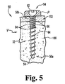
- the bone screw 50 extends along a longitudinal axis L and includes a distal end portion 50a and a proximal end portion 50b.
- the bone screw 50 generally includes a threaded shank portion 52 adapted for engagement within bone, and a head portion 54 adapted for coupling with an implant, further details of which will be set forth below.
- the bone screw 50 may be formed of any suitable biocompatible material such as, for example, titanium, a titanium alloy, stainless steel, metallic alloys, or other materials known to those of skill in the art that possess the mechanical and biocompatible properties suitable for implantation within the body and attachment to bone.
- the threaded shank 52 includes a distal tip 56 that is configured to penetrate bone.
- the distal tip 56 is tapered or pointed to facilitate entry into bone.
- the distal tip 56 may define a blunt or rounded end.
- the distal tip 56 or other portions of the distal end portion 50a may be provided with one or more cutting edges or flutes (not shown) to provide the bone screw 50 with self-cutting or self-tapping capabilities.
- the bone screw 50 may be provided with an axial passage (not shown) extending from the proximal end portion 50b and partially or entirely therethrough to define a cannulation opening, and may be further provided with transverse passages that communicate with the axial passage to define fenestration openings.
- the cannulation and fenestration openings may be used to deliver material such as, for example, bone cement from the proximal end portion 50b of the bone screw 50 and into areas of the bone axially or laterally adjacent the distal end portion 50a or other portions of the threaded shank 52.
- the head portion 54 comprises a relatively smooth shaft or stem 58 configured to slidably receive an implant member or a connector for coupling to an implant member.
- screw head portions 54 are also contemplated, several examples of which will be discussed below.
- bone screw embodiments are also contemplated which do not include a screw head portion.
- the bone screw 50, and particularly the screw head portion 54 preferably includes features that allow for releasable engagement with a driving tool or instrument (not shown) such as, for example, a screwdriver.
- the screw head portion 54 may define a cavity or recess (not shown) sized and shaped to receive a distal end portion of a driver tool.
- the cavity or recess is preferably non-circular such as, for example, hexagonal or rectangular shaped to provide non-rotational engagement between the head portion 54 and the driver tool to facilitate driving engagement of the bone screw 50 into bone.
- the screw head portion 54 may define external surface features for engagement by the distal end portion of a driver tool.
- the threaded shank 52 has an overall length l and defines a first threaded section 60 extending along a first shank length l 1 from the distal end portion 50a toward the proximal end portion 50b, and a second threaded section 62 extending contiguously from the first threaded section 60 to the proximal end portion 50b along a second shank length l 2 .
- the first threaded section 60 includes a first threading 64 that is adapted for anchoring in the cancellous region of a bone
- the second threaded section 62 includes a relatively finer threading 66 that is adapted for anchoring in the cortical region of the bone.
- the second threaded section 62 may define a thread run out 68 adjacent the proximal end portion 50b of the threaded shank 52.
- the length l 1 of the first threaded section 60 extends along at least about one half of the overall length l of the threaded shank 52, with the length l 2 of the second threaded section 62 extending along the remainder of the overall shank length l . In another embodiment, the length l 1 of the first threaded section 60 extends along at least about two-thirds of the overall length l of the threaded shank 52, with the length l 2 of the second threaded section 62 extending along the remainder of the overall shank length l .
- the length l 1 of the first threaded section 60 extends along at least about three-quarters of the overall length l of the threaded shank 52, with the length l 2 of the second threaded section 62 extending along the remainder of the overall shank length l .
- other lengths l 1 of the first threaded section 60 relative to the overall length l of the threaded shank 52 are also contemplated as falling within the scope of the present invention.
- the particular ratio between the shank lengths l 1 , / 2 associated with the first and second threaded sections 60, 62 should preferably be selected based on the characteristics of the bone to which the bone screw 50 is to be engaged.
- the first threaded section 60 includes thread features that are particularly suited for anchoring in the cancellous region of bone
- the second threaded section 62 includes thread features that are particularly suited for anchoring in the cortical region of bone.
- the lengths l 1 , l 2 of the first and second threaded sections should preferably correspond to the desired anchoring depth within the cancellous region of bone and the thickness of the cortical region of bone, respectively.
- the first threading 64 includes a single lead in the form of a helical thread pattern which defines the first threaded section 60, and the second threading 66 cooperates with the first threading 64 to provide a dual lead in the form of double helical thread pattern which defines the second threaded section 62.
- the first and second threadings or leads 64, 66 are provided in the form of a helix that extends substantially continuously about the longitudinal axis L and along the length of the shank portion 52.
- the threadings 64, 66 appear to spiral together along the length l 2 of the second threaded section 62 as a continuous thread, but which in actuality comprise separate threadings. As will be discussed below, providing separate threadings along the second threaded section 62 allows the thread pitch associated with each of the first and second threaded sections 60 and 62 to be equal if so desired.
- the first threading 64 has a first thread pitch p 1
- the second threading 66 is interleaved with the first threading 64 and has a second thread pitch p 2 that is substantially equal to the first thread pitch p 1 .
- first and second threadings 64, 66 cooperate with one another to provide a dual lead thread defining the second threaded section 62, and since the first and second threadings 64, 66 have a substantially equal thread pitch p , engagement of the second threaded section 62 into bone will not require any additional turns relative to the first threaded section 60.
- the second threading 66 is offset about 180 degrees relative to the first threading 64 such that the turns of the second threading 66 are substantially centered between adjacent turns of the first threading 64.
- providing the first threading 64 with a single lead thread having a relatively large thread pitch tends to increase cancellous bone purchase capabilities, while at the same time maintaining the strength and structural integrity of the cancellous bone.
- providing the second threading 66 with a dual lead thread provides increased fixation strength and stability within the relatively harder and denser cortical bone.
- providing the second threaded section 62 with a dual lead thread having the same thread pitch p as the first threaded section 60 will not require any additional turns of the bone screw 50 for engagement within cortical bone as compared to engagement of the first threaded section 60 within cancellous bone.
- the first and second threaded sections 60, 62 define an inner thread root diameter d i that varies between the distal end portion 50a and the proximal end portion 50b.
- the inner thread root diameter d i increases from a first root diameter d 1 adjacent the distal end portion 50a, to a larger second root diameter d 2 adjacent a mid-section of the threaded shank 52, to an even larger third root diameter d 3 adjacent the proximal end portion 50b.
- the inner thread root diameter d i increases uniformly between the root diameter d 1 adjacent the distal end portion 50a and the root diameter d 3 adjacent the proximal end portion 50b.
- the inner thread root diameter d i increases along substantially the entire length l of the threaded shank 52 between the distal end portion 50a and the proximal end portion 50b. In one specific embodiment, the inner thread root diameter d i increases by at least about 15% between the root diameter d 1 adjacent the distal end portion 50a and the root diameter d 3 adjacent the proximal end portion 50b. In another specific embodiment, the inner thread root diameter d i increases by at least about 25% between the root diameter d 1 and the root diameter d 3 . In a further specific embodiment, the inner thread root diameter d i increases by at least about 50% between the root diameter d 1 and the diameter d 3 .
- first and second threadings 64, 66 as measured from the thread root diameter to the outer thread diameter
- providing the first threading 64 with a relatively large thread depth (or a relatively small root diameter d i ) provides increased cancellous bone purchase capabilities and desirable pullout characteristics compared to the smaller thread depth associated with the second threading 66.
- the thread depth of the first and second threadings 64, 66 decreases by at least about 50% from the distal end portion 50a toward the proximal end portion 50b, As should be appreciated, the thread depth of the threadings 64, 66 is maximized along the first threaded section 60, and particularly adjacent the distal end portion 50a, to provided increased cancellous bone purchase capabilities and desirable pullout characteristics.
- the first and second threaded sections 60, 62 define a substantially uniform outer thread diameter d o between the distal end portion 50a and the proximal end portion 50b.
- the outer thread diameter d o is at least about 15% greater than the inner thread root diameter d i adjacent the distal end portion 50a.
- the outer thread diameter d o is at least about 25% greater than the inner thread root diameter d i adjacent the distal end portion 50a.
- the outer thread diameter d o is at least about 50% greater than the inner thread root diameter d i adjacent the distal end portion 50a.
- a larger variation between the outer thread diameter d o and the inner thread root diameter d i tends to increase bone purchase capabilities, which is particularly suitable along the first threaded section 60 that is engaged in cancellous bone.
- the thread pitch p adjacent the distal end portion 50a is equal to or greater than the inner thread root diameter d i adjacent the distal end portion 50a. In one embodiment, the thread pitch p is equal to or greater than the inner thread root diameter d i along substantially the entire length l 1 of the first threaded section 60 of the threaded shank 52. In another embodiment, the thread pitch p is equal to or greater than the inner thread root diameter d i along substantially the entire overall length l of the threaded shank 52.
- the head portion 54 of the bone screw 50 is preferably adapted for coupling with an implant.
- the screw head portion 54 comprises an unthreaded stem portion or shaft 58
- the implant comprises an elongate spinal rod R that is coupled to the screw head 54 via a connector mechanism 70.
- the connector mechanism 70 includes a connector body 72 defining a first passage 74a for receiving the stem portion 58 of the screw head 54, and a second passage 74b for receiving the spinal rod R.
- An interface member 76 may be positioned between the spinal rod R and the stem portion 58, and a fastener or set screw 78 is threaded through an opening in the connector body 72 and into contact with the spinal rod R, which in turn engages the interface member 76 with the stem portion 58 of the screw head 54 to fix the angular relationship between the spinal rod R and the bone screw 50.
- a fastener or set screw 78 is threaded through an opening in the connector body 72 and into contact with the spinal rod R, which in turn engages the interface member 76 with the stem portion 58 of the screw head 54 to fix the angular relationship between the spinal rod R and the bone screw 50.
- the bone screw 80 for coupling with a spinal rod R.
- the bone screw 80 includes a threaded shank 52 and a head 84 that is adapted for coupling with a spinal rod R.
- the threaded shank 52 is identical to that described above and illustrated in Figures 2 and 3 .
- the bone screw bead 84 defines a U-shaped channel 86 that is sized to receive the spinal rod R therein, with the spinal rod R captured within the channel 86 via a fastener or set screw 88 engaged with the bone screw head 84.
- the spinal plate P includes one or more openings 92 for receiving one or more of the bone screws 90, with the bone screw 90 including an enlarged head portion 94.
- the opening 92 includes a lower portion sized to receive the threaded shank 52 therethrough, and an upper portion sized to receive the enlarged bone screw head 94.
- the bone screw 90' includes a threaded shank 52, an enlarged head portion 94', and a threaded stem portion 96 extending from the enlarged head 94', with the spinal plate P' including one or more openings 92' for receiving the threaded stem portion 96 of one or more of the bone screws 90' therethrough, and with the spinal plate P' secured to the bone screw 90' via a lock nut 98 threaded onto the stem portion 96, thereby capturing the spinal plate P between the enlarged head 94' and the lock nut 98.
- the bone screw 90' illustrated in FIG. 6 allows the spinal plate P' to be spaced from the outer surface of the bone.
- the bone comprises a vertebral body V having an inner cancellous bone region 100 and an outer cortical bone region 102.
- the outer cortical bone region 102 of the vertebral body V is relatively harder and denser compared to the inner cancellous bone region 100.
- the threaded shank 52 of the bone screw is driven into engagement with the vertebral body V, with the first threaded section 60 including the single lead threading 64 engaged within the inner cancellous bone region 100, and with the relatively finer second threaded section 62 including the dual lead threading 66 engaged within the outer cortical bone region 102.
- the relatively course single lead threading 64 provides increased bone purchase capabilities and desirable pullout characteristics compared to the finer dual lead threading 66, which is particularly advantageous for anchoring within soft cancellous bone.
- the relatively fine dual lead threading 66 provides increased fixation strength and stability compared to the courser single lead threading 64, which is particularly advantageous for fixation within relatively harder and denser cortical bone.
- a spinal implant such as a rod or plate may be coupled to one or more bone screws which are in turn anchored to corresponding vertebral bodies V for treatment of the spinal column.
- the bone screws of the present invention may be anchored within any number of vertebral bodies V, including a single vertebral body or two or more vertebral bodies. In one embodiment of the invention, the bone screws are anchored within the pedicle region of a vertebral body. However, it should be understood that the bone screws may be anchored to other portions or regions of a vertebral body. It should also be understood that the bone screws of the present invention may be anchored to a posterior, anterior, lateral, posterolateral or anterolateral aspect of the vertebral body V. It should further be understood that the bone screws of the present invention may be attached to any region of the spinal column, including the cervical, thoracic, or lumbar regions of spinal column. It should likewise be understood that the bone screws of the present invention may be attached to bone structures other than vertebral bodies, such as, for example, bones associated with the arm or leg.
Landscapes
- Health & Medical Sciences (AREA)
- Orthopedic Medicine & Surgery (AREA)
- Life Sciences & Earth Sciences (AREA)
- Surgery (AREA)
- Neurology (AREA)
- Heart & Thoracic Surgery (AREA)
- Engineering & Computer Science (AREA)
- Biomedical Technology (AREA)
- Nuclear Medicine, Radiotherapy & Molecular Imaging (AREA)
- Medical Informatics (AREA)
- Molecular Biology (AREA)
- Animal Behavior & Ethology (AREA)
- General Health & Medical Sciences (AREA)
- Public Health (AREA)
- Veterinary Medicine (AREA)
- Surgical Instruments (AREA)
- Prostheses (AREA)
- Materials For Medical Uses (AREA)
Applications Claiming Priority (2)
| Application Number | Priority Date | Filing Date | Title |
|---|---|---|---|
| US11/355,877 US8075604B2 (en) | 2006-02-16 | 2006-02-16 | Multi-thread bone screw and method |
| EP07717588A EP1991145B1 (fr) | 2006-02-16 | 2007-02-08 | Vis pour osteosynthese a pas multiples |
Related Parent Applications (1)
| Application Number | Title | Priority Date | Filing Date |
|---|---|---|---|
| EP07717588.3 Division | 2007-02-08 |
Publications (1)
| Publication Number | Publication Date |
|---|---|
| EP2233095A1 true EP2233095A1 (fr) | 2010-09-29 |
Family
ID=37944107
Family Applications (2)
| Application Number | Title | Priority Date | Filing Date |
|---|---|---|---|
| EP07717588A Active EP1991145B1 (fr) | 2006-02-16 | 2007-02-08 | Vis pour osteosynthese a pas multiples |
| EP10169737A Withdrawn EP2233095A1 (fr) | 2006-02-16 | 2007-02-08 | Vis pour osteosynthèse à pas multiples |
Family Applications Before (1)
| Application Number | Title | Priority Date | Filing Date |
|---|---|---|---|
| EP07717588A Active EP1991145B1 (fr) | 2006-02-16 | 2007-02-08 | Vis pour osteosynthese a pas multiples |
Country Status (13)
| Country | Link |
|---|---|
| US (3) | US8075604B2 (fr) |
| EP (2) | EP1991145B1 (fr) |
| JP (1) | JP2009527279A (fr) |
| KR (1) | KR101066312B1 (fr) |
| CN (1) | CN101394802B (fr) |
| AT (1) | ATE480196T1 (fr) |
| AU (1) | AU2007214936B2 (fr) |
| DE (1) | DE602007009050D1 (fr) |
| DK (1) | DK1991145T3 (fr) |
| ES (1) | ES2352689T3 (fr) |
| PL (1) | PL1991145T3 (fr) |
| PT (1) | PT1991145E (fr) |
| WO (1) | WO2007095447A1 (fr) |
Families Citing this family (109)
| Publication number | Priority date | Publication date | Assignee | Title |
|---|---|---|---|---|
| WO2006029274A1 (fr) * | 2004-09-07 | 2006-03-16 | Smith & Nephew, Inc. | Mecanisme de blocage de plaque vissee presentant une epaisseur minimale |
| US9980753B2 (en) * | 2009-06-15 | 2018-05-29 | Roger P Jackson | pivotal anchor with snap-in-place insert having rotation blocking extensions |
| US8740955B2 (en) * | 2005-02-15 | 2014-06-03 | Zimmer, Inc. | Bone screw with multiple thread profiles for far cortical locking and flexible engagement to a bone |
| US7559846B2 (en) * | 2005-10-28 | 2009-07-14 | Sandvik Medical Solutions Oregon, Inc. | Machining method and apparatus for thread formation on workpiece |
| US8491302B2 (en) * | 2006-03-21 | 2013-07-23 | Uri Arni | Dental implant |
| US8114128B2 (en) | 2006-11-01 | 2012-02-14 | Depuy Mitek, Inc. | Cannulated suture anchor |
| US8128671B2 (en) * | 2007-04-04 | 2012-03-06 | Warsaw Orthopedic, Inc. | Variable flank bone screw |
| US20140142636A1 (en) * | 2007-04-16 | 2014-05-22 | Robert Hes | Bone Screw |
| AU2014250694B2 (en) * | 2007-09-14 | 2015-10-08 | Depuy Mitek, Inc. | Dual thread cannulated suture anchor |
| US8702754B2 (en) | 2007-09-14 | 2014-04-22 | Depuy Mitek, Llc | Methods for anchoring suture to bone |
| US8882801B2 (en) | 2007-09-14 | 2014-11-11 | Depuy Mitek, Llc | Dual thread cannulated suture anchor |
| ES2321573B1 (es) * | 2007-12-07 | 2010-03-26 | Juan Carlos Garcia Saban | Implante dental post-extraccion. |
| US20100049253A1 (en) * | 2008-08-20 | 2010-02-25 | Warsaw Orthopedic, Inc. | Bottom loading connector for attaching a spinal rod to a vertebral member |
| KR100904915B1 (ko) | 2008-10-02 | 2009-06-29 | (주) 코리아나메디칼 | 척추 고정 스크류 |
| US20100094352A1 (en) * | 2008-10-10 | 2010-04-15 | Andrew Iott | Bone screw |
| US20140012322A1 (en) * | 2008-10-10 | 2014-01-09 | Brian Gayvey | Bone Screw |
| CN102271731B (zh) | 2008-10-30 | 2015-11-25 | 德普伊斯派尔公司 | 用于向骨锚钉递送骨粘固剂的系统和方法 |
| WO2010067363A1 (fr) * | 2008-12-09 | 2010-06-17 | Mazor Surgical Technologies Ltd. | Vis orthopedique a filet double |
| KR101041373B1 (ko) * | 2009-04-30 | 2011-06-15 | 김민석 | 이중 나선형을 갖는 세트스크루를 포함하는 척추 고정장치 |
| US9095444B2 (en) | 2009-07-24 | 2015-08-04 | Warsaw Orthopedic, Inc. | Implant with an interference fit fastener |
| US20110082338A1 (en) * | 2009-10-01 | 2011-04-07 | Tyco Healthcare Group Lp | Port fixation with varying thread pitch |
| US20110087295A1 (en) * | 2009-10-12 | 2011-04-14 | University Of Utah | Bone fixation systems |
| US20110106157A1 (en) * | 2009-10-30 | 2011-05-05 | Warsaw Orthropedic, Inc. | Self-Locking Interference Bone Screw for use with Spinal Implant |
| EP2496162B1 (fr) * | 2009-11-05 | 2018-10-31 | K2M, Inc. | Vis à os semi-retenue |
| CN102068305B (zh) * | 2009-11-20 | 2016-01-20 | 上海微创骨科医疗科技有限公司 | 骨螺钉 |
| EP2571435A4 (fr) * | 2010-05-19 | 2014-09-17 | Depuy Spine Inc | Ancrages osseux |
| US8469998B2 (en) | 2010-08-30 | 2013-06-25 | Depuy Mitek, Llc | Knotless suture anchor |
| US8460340B2 (en) | 2010-08-30 | 2013-06-11 | Depuy Mitek, Llc | Knotless suture anchor |
| US8435264B2 (en) | 2010-08-30 | 2013-05-07 | Depuy Mitek, Llc | Knotless suture anchor and driver |
| BR112013015210B1 (pt) * | 2010-12-15 | 2020-12-15 | Leo Arieh Pinczewski | Aparelho para ancoragem de um membro flexível |
| US20120197309A1 (en) * | 2011-01-28 | 2012-08-02 | Warsaw Orthopedic, Inc. | Bone Anchor Including an Elongate Post With Break-Off Features |
| DE102011101253A1 (de) * | 2011-02-16 | 2012-08-16 | Hager & Meisinger Gmbh | Knochenschraube |
| US8562651B2 (en) * | 2011-03-30 | 2013-10-22 | Warsaw Orthopedic, Inc. | Sacroiliac terminal anchor device and method |
| US20120298820A1 (en) * | 2011-05-25 | 2012-11-29 | Spiros Manolidis | Surgical tool holder |
| JP5823752B2 (ja) * | 2011-07-14 | 2015-11-25 | 株式会社パイオラックスメディカルデバイス | 骨固定用ネジ |
| JP5156113B2 (ja) * | 2011-08-02 | 2013-03-06 | 株式会社松風 | 歯科用インプラント |
| US9155580B2 (en) | 2011-08-25 | 2015-10-13 | Medos International Sarl | Multi-threaded cannulated bone anchors |
| US20130218213A1 (en) * | 2012-02-22 | 2013-08-22 | Zimmer Spine, Inc. | Bone screw including a dual thread closure member |
| US20130253594A1 (en) * | 2012-03-26 | 2013-09-26 | Spartek Medical, Inc. | System and method for securing an implant to a bone containing bone cement |
| US9452005B2 (en) | 2012-08-23 | 2016-09-27 | DePuy Synthes Products, Inc. | Bone fixation system |
| RU2648850C2 (ru) * | 2012-08-23 | 2018-03-28 | Зинтес Гмбх | Система фиксации кости |
| US10004603B2 (en) | 2012-08-23 | 2018-06-26 | DePuy Synthes Products, Inc. | Bone implant |
| US9079263B2 (en) * | 2012-08-24 | 2015-07-14 | RTG Scientific, Inc. | Orthopedic fastener method |
| CN103876817A (zh) * | 2012-12-21 | 2014-06-25 | 江苏安格尔医疗器械有限公司 | 一种多头螺纹u形钉 |
| CN103040517A (zh) * | 2012-12-27 | 2013-04-17 | 苏州欣荣博尔特医疗器械有限公司 | 脊柱单摆螺钉 |
| CN103006308A (zh) * | 2012-12-27 | 2013-04-03 | 苏州欣荣博尔特医疗器械有限公司 | 脊柱螺钉 |
| US9687284B2 (en) | 2013-02-13 | 2017-06-27 | Stryker European Holdings I, Llc | Locking peg with extended thread |
| US10058368B2 (en) * | 2013-12-26 | 2018-08-28 | Skeletal Dynamics, Llc | Headless compression screw |
| US9463057B2 (en) | 2014-01-16 | 2016-10-11 | Amendia, Inc. | Orthopedic fastener |
| US20160015438A1 (en) * | 2014-07-17 | 2016-01-21 | Phalanx, Llc | Bone anchor device |
| WO2016041001A1 (fr) * | 2014-09-15 | 2016-03-24 | Cryptych Pty Ltd | Marqueur fiduciaire |
| CN107427339A (zh) * | 2014-12-31 | 2017-12-01 | 科特斯种植牙实业公司 | 具有黄金比例的牙种植体 |
| DE102015008036A1 (de) * | 2015-06-09 | 2016-12-15 | Signus Medizintechnik Gmbh | Pedikelschraube mit Tulpe |
| DE102015109481A1 (de) * | 2015-06-15 | 2016-12-15 | Aesculap Ag | Pedikelschraube mit radial versetzter Führung |
| WO2017058965A1 (fr) * | 2015-09-28 | 2017-04-06 | Regenimmune, Inc. | Vis osseuse modulaire améliorée destinée à la fixation chirurgicale à un os |
| KR101609582B1 (ko) | 2015-10-19 | 2016-04-06 | (주)엘앤케이바이오메드 | 수술용 스크류 및 이를 이용한 융합장치 |
| KR101609581B1 (ko) | 2015-10-19 | 2016-04-06 | (주)엘앤케이바이오메드 | 수술용 스크류 및 이를 이용한 융합장치 |
| US10188430B2 (en) * | 2015-11-16 | 2019-01-29 | Clariance | Double-threaded bone screw |
| FR3043540B1 (fr) | 2015-11-16 | 2017-12-29 | Clariance | Vis osseuse a double filet |
| FR3046534B1 (fr) * | 2016-01-13 | 2021-12-10 | Neuro France Implants | Dispositif d'implant |
| KR101731421B1 (ko) * | 2016-01-29 | 2017-05-04 | (주)아이엠아이 | 척추경 나사못 |
| USD812751S1 (en) | 2016-02-03 | 2018-03-13 | Karl Storz Gmbh & Co. Kg | Interference bone screw |
| CN105877798B (zh) * | 2016-04-06 | 2019-07-23 | 江苏百易得医疗科技有限公司 | 一种带线锚钉及其手柄 |
| CN105963006A (zh) * | 2016-04-22 | 2016-09-28 | 深圳市斯玛仪器有限公司 | 一种椎弓根固定器及固定系统 |
| KR101868694B1 (ko) * | 2016-10-21 | 2018-06-18 | 주식회사 지비에스커먼웰스 | 뼈 고정 스크류 장치 및 그 체결방법 |
| CN106510828A (zh) * | 2016-12-28 | 2017-03-22 | 苏州欣荣博尔特医疗器械有限公司 | 骨水泥螺钉 |
| KR101863877B1 (ko) | 2017-01-18 | 2018-06-01 | (주)올소테크 | 임플란트용 가변 피치형 테이퍼 무두나사의 제조방법 및 이에 제조된 임플란트용 가변 피치형 테이퍼 무두나사 |
| KR101813525B1 (ko) | 2017-01-23 | 2017-12-29 | 주식회사 앤트테크놀로지 | 4줄 나사산을 구비하는 척추경 나사못 |
| US11376050B2 (en) | 2017-06-27 | 2022-07-05 | Medos International Sarl | Bone screw |
| BR102017015490B1 (pt) * | 2017-07-19 | 2022-07-26 | Jjgc Indústria E Comércio De Materiais Dentários S.A. | Implante dentário |
| JP2020532407A (ja) * | 2017-09-05 | 2020-11-12 | エクソームド コーポレーションExsomed Corporation | 径方向皮質固定用のねじ山付き髄内釘 |
| EP3694431A1 (fr) | 2017-10-09 | 2020-08-19 | CONMED Corporation | Vis à os canulée à démarrage facile |
| US10772667B2 (en) | 2017-12-22 | 2020-09-15 | Medos International Sarl | Bone screw with cutting tip |
| CN108113743A (zh) * | 2018-01-03 | 2018-06-05 | 北京爱康宜诚医疗器材有限公司 | 骨螺钉 |
| US11000325B2 (en) * | 2018-02-27 | 2021-05-11 | Acumed Llc | Bone fastener with partially overlapping threads and a varying lead |
| KR20190102897A (ko) * | 2018-02-27 | 2019-09-04 | (주)엘앤케이바이오메드 | 통합형 사측방 척추 유합 케이지 |
| CN108175495B (zh) * | 2018-03-09 | 2024-03-26 | 中南大学 | 一种接骨用螺钉及具有该螺钉的接骨板组件 |
| US10575886B2 (en) * | 2018-05-09 | 2020-03-03 | Warsaw Orthopedic, Inc. | Bone screw and method of manufacture |
| US11266453B2 (en) * | 2018-09-21 | 2022-03-08 | DePuy Synthes Products, Inc. | Bone compression screws and related systems and methods |
| US11357901B2 (en) | 2018-10-05 | 2022-06-14 | Sustain Medical, LLC | Surgical suction filter |
| USD954958S1 (en) | 2018-10-05 | 2022-06-14 | Sustain Medical, LLC | Surgical suction filter |
| CN114600165B (zh) | 2019-09-17 | 2025-08-15 | 波士顿偏振测定公司 | 用于使用偏振提示表面建模的系统和方法 |
| US11311317B2 (en) | 2019-09-25 | 2022-04-26 | Stelios KOUTSOUMBELIS | Spinal fixation device with rotatable connector |
| EP4042366A4 (fr) | 2019-10-07 | 2023-11-15 | Boston Polarimetrics, Inc. | Systèmes et procédés d'augmentation de systèmes de capteur et de systèmes d'imagerie avec polarisation |
| WO2021108002A1 (fr) | 2019-11-30 | 2021-06-03 | Boston Polarimetrics, Inc. | Systèmes et procédés de segmentation d'objets transparents au moyen de files d'attentes de polarisation |
| KR102942542B1 (ko) | 2020-01-29 | 2026-03-23 | 인트린식 이노베이션 엘엘씨 | 물체 포즈 검출 및 측정 시스템들을 특성화하기 위한 시스템들 및 방법들 |
| WO2021154459A1 (fr) | 2020-01-30 | 2021-08-05 | Boston Polarimetrics, Inc. | Systèmes et procédés de synthèse de données pour l'apprentissage de modèles statistiques sur différentes modalités d'imagerie comprenant des images polarisées |
| US12137946B2 (en) | 2020-03-17 | 2024-11-12 | Aegis Spine, Inc. | Spinal plate |
| WO2021243088A1 (fr) | 2020-05-27 | 2021-12-02 | Boston Polarimetrics, Inc. | Systèmes optiques de polarisation à ouvertures multiples utilisant des diviseurs de faisceau |
| CN112716589A (zh) * | 2021-01-05 | 2021-04-30 | 上海睿触科技有限公司 | 一种新型骨钉结构 |
| DE102021000210A1 (de) * | 2021-01-19 | 2022-07-21 | Mimeo Medical Gmbh | Schraubenelement und Verfahren zur additiven Herstellung |
| US20220249131A1 (en) * | 2021-02-09 | 2022-08-11 | Rtg Scientific, Llc | Fastening devices, systems, and methods |
| US12069227B2 (en) | 2021-03-10 | 2024-08-20 | Intrinsic Innovation Llc | Multi-modal and multi-spectral stereo camera arrays |
| US12020455B2 (en) | 2021-03-10 | 2024-06-25 | Intrinsic Innovation Llc | Systems and methods for high dynamic range image reconstruction |
| US11954886B2 (en) | 2021-04-15 | 2024-04-09 | Intrinsic Innovation Llc | Systems and methods for six-degree of freedom pose estimation of deformable objects |
| US11290658B1 (en) | 2021-04-15 | 2022-03-29 | Boston Polarimetrics, Inc. | Systems and methods for camera exposure control |
| US12067746B2 (en) | 2021-05-07 | 2024-08-20 | Intrinsic Innovation Llc | Systems and methods for using computer vision to pick up small objects |
| US12175741B2 (en) | 2021-06-22 | 2024-12-24 | Intrinsic Innovation Llc | Systems and methods for a vision guided end effector |
| US12340538B2 (en) | 2021-06-25 | 2025-06-24 | Intrinsic Innovation Llc | Systems and methods for generating and using visual datasets for training computer vision models |
| US12172310B2 (en) | 2021-06-29 | 2024-12-24 | Intrinsic Innovation Llc | Systems and methods for picking objects using 3-D geometry and segmentation |
| US11689813B2 (en) | 2021-07-01 | 2023-06-27 | Intrinsic Innovation Llc | Systems and methods for high dynamic range imaging using crossed polarizers |
| US12293535B2 (en) | 2021-08-03 | 2025-05-06 | Intrinsic Innovation Llc | Systems and methods for training pose estimators in computer vision |
| JP2024530278A (ja) * | 2021-08-26 | 2024-08-16 | イージス・スパイン・インコーポレイテッド | 脊椎プレート |
| CL2022000072A1 (es) * | 2022-01-11 | 2022-08-19 | Brok Spa | Sistema y procedimiento simplificado para cirugía de implantes dentales guiadas por computador. |
| US20230255614A1 (en) * | 2022-02-16 | 2023-08-17 | Hs West Investments, Llc | Suture anchors with locking threads that interlock with adjacent bone tissue |
| CN115154676A (zh) * | 2022-07-01 | 2022-10-11 | 西藏自治区人民政府驻成都办事处医院 | 一种生物固定型椎弓根螺钉及其制备方法与应用 |
| JP2024030858A (ja) * | 2022-08-25 | 2024-03-07 | シンフォニーメディカル株式会社 | 椎弓根スクリュー |
| US11832864B1 (en) | 2023-04-12 | 2023-12-05 | OC Medical Devices, LLC | Orthopedic implants and tools |
| CN222208560U (zh) * | 2024-01-02 | 2024-12-20 | 宁德时代新能源科技股份有限公司 | 螺栓、锁附结构及电池 |
Citations (7)
| Publication number | Priority date | Publication date | Assignee | Title |
|---|---|---|---|---|
| US5643263A (en) | 1995-08-14 | 1997-07-01 | Simonson; Peter Melott | Spinal implant connection assembly |
| EP0794336A1 (fr) * | 1996-03-07 | 1997-09-10 | HILTI Aktiengesellschaft | Barre d'ancrage pour dispositif d'ancrage composite |
| US5947967A (en) | 1997-10-22 | 1999-09-07 | Sdgt Holdings, Inc. | Variable angle connector |
| US6030162A (en) * | 1998-12-18 | 2000-02-29 | Acumed, Inc. | Axial tension screw |
| FR2789293A1 (fr) * | 1999-02-10 | 2000-08-11 | Emmanuel Bockx | Dispositif de stabilite vertebrale |
| WO2002009601A2 (fr) * | 2000-08-02 | 2002-02-07 | Orthopaedic Biosystems Ltd., Inc. | Vis medicale et son procede de mise en place |
| US6471703B1 (en) | 1999-04-21 | 2002-10-29 | Sdgi Holdings, Inc. | Variable angle connection assembly for a spinal implant system |
Family Cites Families (45)
| Publication number | Priority date | Publication date | Assignee | Title |
|---|---|---|---|---|
| USRE28111E (en) | 1971-01-04 | 1974-08-13 | Fastener with improved thread construction | |
| US3861269A (en) | 1971-01-04 | 1975-01-21 | Superior Dry Wall Screw Mfg Co | Fastener with improved thread construction |
| CH669724A5 (fr) | 1986-04-15 | 1989-04-14 | Sulzer Ag | |
| US4844676A (en) | 1986-10-23 | 1989-07-04 | Pheoll Manufacturing Company, Inc. | Self-penetrating screw |
| IT1237496B (it) | 1989-10-26 | 1993-06-08 | Giuseppe Vrespa | Dispositivo a vite per l'ancoraggio di protesi alle ossa, metodo per l'applicazione di tale dispositivo e relativa attrezzatura |
| US5120171A (en) * | 1990-11-27 | 1992-06-09 | Stuart Surgical | Bone screw with improved threads |
| CH685850A5 (de) * | 1990-11-26 | 1995-10-31 | Synthes Ag | Verankerungseinrichtung |
| MX9204122A (es) | 1991-07-15 | 1993-04-01 | Danek Group Inc | Sistema para fijacion espinal. |
| AU2312092A (en) | 1992-07-10 | 1994-01-31 | Georg Ihli | Double-threaded bone screw for use in medicine in through-bone osteosynthesis in the fields of accident surgery, traumatology and orthopaedics |
| US5814046A (en) | 1992-11-13 | 1998-09-29 | Sofamor S.N.C. | Pedicular screw and posterior spinal instrumentation |
| US5964768A (en) * | 1993-01-21 | 1999-10-12 | Acumed, Inc. | Tapered bone screw with continuously varying pitch |
| US6984235B2 (en) * | 1993-01-21 | 2006-01-10 | Acumed Llc | System for fusing joints |
| WO1994020040A1 (fr) | 1993-03-01 | 1994-09-15 | Synvasive Technology, Inc. | Dispositif de fixation et de compression possedant un pas de vis non homogene |
| US5409486A (en) | 1993-04-16 | 1995-04-25 | Phoenix Surgical Products, Inc. | Double threaded arthrodesis screw |
| US5385439A (en) | 1993-11-29 | 1995-01-31 | Hurdle; Donald R. | Radial extrusion thread-forming screw |
| US5520688A (en) | 1994-07-20 | 1996-05-28 | Lin; Chih-I | Vertebral auxiliary fixation device |
| US5601553A (en) * | 1994-10-03 | 1997-02-11 | Synthes (U.S.A.) | Locking plate and bone screw |
| US5613968A (en) | 1995-05-01 | 1997-03-25 | Lin; Chih-I | Universal pad fixation device for orthopedic surgery |
| US5607428A (en) | 1995-05-01 | 1997-03-04 | Lin; Kwan C. | Orthopedic fixation device having a double-threaded screw |
| DE59602349D1 (de) | 1996-01-18 | 1999-08-05 | Werner Flueckiger | Distanzschraube |
| DE19735963C2 (de) | 1996-08-20 | 2003-10-23 | Woco Avs Gmbh | Schraube |
| US5779417A (en) | 1997-05-12 | 1998-07-14 | Illinois Tool Works Inc. | Fastener having primary and secondary threads |
| US6214012B1 (en) * | 1998-11-13 | 2001-04-10 | Harrington Arthritis Research Center | Method and apparatus for delivering material to a desired location |
| CA2352185C (fr) | 1998-11-26 | 2008-04-15 | Synthes (U.S.A.) | Vis a os ayant un filetage de diametre constant |
| US6129730A (en) | 1999-02-10 | 2000-10-10 | Depuy Acromed, Inc. | Bi-fed offset pitch bone screw |
| US6045312A (en) | 1999-03-17 | 2000-04-04 | Illinois Tool Works Inc. | Fastener having primary and secondary threads |
| DE19922440A1 (de) | 1999-05-06 | 2000-11-09 | Schaefer Micomed Gmbh | Pedikelschraube |
| US6602256B1 (en) | 1999-10-11 | 2003-08-05 | Cross Medical Products, Inc. | Bone stabilization plate with a secured-locking mechanism for cervical fixation |
| US6224602B1 (en) | 1999-10-11 | 2001-05-01 | Interpore Cross International | Bone stabilization plate with a secured-locking mechanism for cervical fixation |
| US6666638B2 (en) * | 2001-02-15 | 2003-12-23 | Phillips Screw Company | Deck screw having multiple threaded sections |
| US20020156474A1 (en) * | 2001-04-20 | 2002-10-24 | Michael Wack | Polyaxial locking plate |
| US6966737B2 (en) | 2001-08-06 | 2005-11-22 | Olympic Manufacturing Group, Inc. | Deck screws suitable for use with composite lumber |
| US20030062868A1 (en) * | 2001-10-01 | 2003-04-03 | Mir Sayeed A. | Switching methodology for ground referenced voltage controlled electric machine |
| CN1604758A (zh) * | 2001-10-15 | 2005-04-06 | 加里J·里德 | 矫形外科稳定器械和方法 |
| US7066937B2 (en) | 2002-02-13 | 2006-06-27 | Endius Incorporated | Apparatus for connecting a longitudinal member to a bone portion |
| US20030171755A1 (en) * | 2002-03-05 | 2003-09-11 | Moseley Colin F. | Bone screws |
| US7037059B2 (en) | 2003-01-07 | 2006-05-02 | Altenloh, Brinck Co. Gmbh & Co. Kg | Self-tapping screw for composite materials |
| US7582107B2 (en) | 2003-02-03 | 2009-09-01 | Integra Lifesciences Corporation | Compression screw apparatuses, systems and methods |
| US7044953B2 (en) | 2003-02-27 | 2006-05-16 | Stryker Leibinger Gmbh & Co. Kg | Compression bone screw |
| US7270665B2 (en) * | 2003-06-11 | 2007-09-18 | Sdgi Holdings, Inc. | Variable offset spinal fixation system |
| US7819902B2 (en) * | 2004-02-27 | 2010-10-26 | Custom Spine, Inc. | Medialised rod pedicle screw assembly |
| TWI259754B (en) * | 2004-05-18 | 2006-08-01 | Quanta Comp Inc | Extended fin array |
| EP1865862B1 (fr) | 2005-04-04 | 2016-08-24 | Zimmer GmbH | Vis pédiculaire |
| US7559846B2 (en) | 2005-10-28 | 2009-07-14 | Sandvik Medical Solutions Oregon, Inc. | Machining method and apparatus for thread formation on workpiece |
| US8128671B2 (en) | 2007-04-04 | 2012-03-06 | Warsaw Orthopedic, Inc. | Variable flank bone screw |
-
2006
- 2006-02-16 US US11/355,877 patent/US8075604B2/en active Active
-
2007
- 2007-02-08 ES ES07717588T patent/ES2352689T3/es active Active
- 2007-02-08 DE DE602007009050T patent/DE602007009050D1/de active Active
- 2007-02-08 DK DK07717588.3T patent/DK1991145T3/da active
- 2007-02-08 EP EP07717588A patent/EP1991145B1/fr active Active
- 2007-02-08 JP JP2008555439A patent/JP2009527279A/ja active Pending
- 2007-02-08 KR KR1020087022286A patent/KR101066312B1/ko not_active Expired - Fee Related
- 2007-02-08 AT AT07717588T patent/ATE480196T1/de active
- 2007-02-08 AU AU2007214936A patent/AU2007214936B2/en active Active
- 2007-02-08 PL PL07717588T patent/PL1991145T3/pl unknown
- 2007-02-08 EP EP10169737A patent/EP2233095A1/fr not_active Withdrawn
- 2007-02-08 WO PCT/US2007/061839 patent/WO2007095447A1/fr not_active Ceased
- 2007-02-08 CN CN2007800055869A patent/CN101394802B/zh active Active
- 2007-02-08 PT PT07717588T patent/PT1991145E/pt unknown
-
2011
- 2011-12-12 US US13/323,546 patent/US9247976B2/en not_active Expired - Lifetime
-
2015
- 2015-12-31 US US14/985,903 patent/US20160113693A1/en not_active Abandoned
Patent Citations (7)
| Publication number | Priority date | Publication date | Assignee | Title |
|---|---|---|---|---|
| US5643263A (en) | 1995-08-14 | 1997-07-01 | Simonson; Peter Melott | Spinal implant connection assembly |
| EP0794336A1 (fr) * | 1996-03-07 | 1997-09-10 | HILTI Aktiengesellschaft | Barre d'ancrage pour dispositif d'ancrage composite |
| US5947967A (en) | 1997-10-22 | 1999-09-07 | Sdgt Holdings, Inc. | Variable angle connector |
| US6030162A (en) * | 1998-12-18 | 2000-02-29 | Acumed, Inc. | Axial tension screw |
| FR2789293A1 (fr) * | 1999-02-10 | 2000-08-11 | Emmanuel Bockx | Dispositif de stabilite vertebrale |
| US6471703B1 (en) | 1999-04-21 | 2002-10-29 | Sdgi Holdings, Inc. | Variable angle connection assembly for a spinal implant system |
| WO2002009601A2 (fr) * | 2000-08-02 | 2002-02-07 | Orthopaedic Biosystems Ltd., Inc. | Vis medicale et son procede de mise en place |
Also Published As
| Publication number | Publication date |
|---|---|
| ATE480196T1 (de) | 2010-09-15 |
| US9247976B2 (en) | 2016-02-02 |
| WO2007095447A1 (fr) | 2007-08-23 |
| KR101066312B1 (ko) | 2011-09-20 |
| EP1991145A1 (fr) | 2008-11-19 |
| US8075604B2 (en) | 2011-12-13 |
| US20120116464A1 (en) | 2012-05-10 |
| PL1991145T3 (pl) | 2011-04-29 |
| DE602007009050D1 (de) | 2010-10-21 |
| AU2007214936B2 (en) | 2013-09-12 |
| KR20080102188A (ko) | 2008-11-24 |
| JP2009527279A (ja) | 2009-07-30 |
| EP1991145B1 (fr) | 2010-09-08 |
| US20160113693A1 (en) | 2016-04-28 |
| US20070233122A1 (en) | 2007-10-04 |
| CN101394802A (zh) | 2009-03-25 |
| CN101394802B (zh) | 2011-11-16 |
| DK1991145T3 (da) | 2011-01-10 |
| PT1991145E (pt) | 2010-12-14 |
| ES2352689T3 (es) | 2011-02-22 |
| AU2007214936A1 (en) | 2007-08-23 |
Similar Documents
| Publication | Publication Date | Title |
|---|---|---|
| US8075604B2 (en) | Multi-thread bone screw and method | |
| US8128671B2 (en) | Variable flank bone screw | |
| US7850717B2 (en) | Bone anchors having two or more portions exhibiting different performance characteristics and method of forming the same | |
| US8523914B2 (en) | Bone anchor with predetermined break point and removal features | |
| JP2007530216A (ja) | ダブルリードの骨ねじ | |
| US7325470B2 (en) | Self-centering screw and retaining screw driver for use in surgery | |
| US5743914A (en) | Bone screw | |
| US20110295319A1 (en) | Dynamic pedicle screw | |
| US20040243129A1 (en) | Double helical threaded bone screw | |
| US10405890B2 (en) | Helical bone fixation device | |
| US20110106157A1 (en) | Self-Locking Interference Bone Screw for use with Spinal Implant | |
| WO2021059300A1 (fr) | Vis cortico-annulo-corticale améliorée | |
| US20120197312A1 (en) | Thread introduction features for an orthopedic implant | |
| RU236827U1 (ru) | Канюлированный ортопедический винт | |
| US12096966B2 (en) | Bone anchor | |
| WO2000040165A1 (fr) | Dispositif de vis orthopedique |
Legal Events
| Date | Code | Title | Description |
|---|---|---|---|
| PUAI | Public reference made under article 153(3) epc to a published international application that has entered the european phase |
Free format text: ORIGINAL CODE: 0009012 |
|
| 17P | Request for examination filed |
Effective date: 20100715 |
|
| AC | Divisional application: reference to earlier application |
Ref document number: 1991145 Country of ref document: EP Kind code of ref document: P |
|
| AK | Designated contracting states |
Kind code of ref document: A1 Designated state(s): AT BE BG CH CY CZ DE DK EE ES FI FR GB GR HU IE IS IT LI LT LU LV MC NL PL PT RO SE SI SK TR |
|
| STAA | Information on the status of an ep patent application or granted ep patent |
Free format text: STATUS: THE APPLICATION HAS BEEN WITHDRAWN |
|
| 18W | Application withdrawn |
Effective date: 20110414 |