EP2233197A2 - Véhicule à monture - Google Patents
Véhicule à monture Download PDFInfo
- Publication number
- EP2233197A2 EP2233197A2 EP09176627A EP09176627A EP2233197A2 EP 2233197 A2 EP2233197 A2 EP 2233197A2 EP 09176627 A EP09176627 A EP 09176627A EP 09176627 A EP09176627 A EP 09176627A EP 2233197 A2 EP2233197 A2 EP 2233197A2
- Authority
- EP
- European Patent Office
- Prior art keywords
- catalyst
- amount
- exhaust gas
- zeolite
- saddle
- Prior art date
- Legal status (The legal status is an assumption and is not a legal conclusion. Google has not performed a legal analysis and makes no representation as to the accuracy of the status listed.)
- Granted
Links
Images


Classifications
-
- F—MECHANICAL ENGINEERING; LIGHTING; HEATING; WEAPONS; BLASTING
- F01—MACHINES OR ENGINES IN GENERAL; ENGINE PLANTS IN GENERAL; STEAM ENGINES
- F01N—GAS-FLOW SILENCERS OR EXHAUST APPARATUS FOR MACHINES OR ENGINES IN GENERAL; GAS-FLOW SILENCERS OR EXHAUST APPARATUS FOR INTERNAL-COMBUSTION ENGINES
- F01N3/00—Exhaust or silencing apparatus having means for purifying, rendering innocuous, or otherwise treating exhaust
- F01N3/08—Exhaust or silencing apparatus having means for purifying, rendering innocuous, or otherwise treating exhaust for rendering innocuous
- F01N3/10—Exhaust or silencing apparatus having means for purifying, rendering innocuous, or otherwise treating exhaust for rendering innocuous by thermal or catalytic conversion of noxious components of exhaust
- F01N3/24—Exhaust or silencing apparatus having means for purifying, rendering innocuous, or otherwise treating exhaust for rendering innocuous by thermal or catalytic conversion of noxious components of exhaust characterised by constructional aspects of converting apparatus
- F01N3/30—Arrangements for supply of additional air
-
- B—PERFORMING OPERATIONS; TRANSPORTING
- B01—PHYSICAL OR CHEMICAL PROCESSES OR APPARATUS IN GENERAL
- B01D—SEPARATION
- B01D53/00—Separation of gases or vapours; Recovering vapours of volatile solvents from gases; Chemical or biological purification of waste gases, e.g. engine exhaust gases, smoke, fumes, flue gases, aerosols
- B01D53/34—Chemical or biological purification of waste gases
- B01D53/92—Chemical or biological purification of waste gases of engine exhaust gases
- B01D53/94—Chemical or biological purification of waste gases of engine exhaust gases by catalytic processes
- B01D53/9445—Simultaneously removing carbon monoxide, hydrocarbons or nitrogen oxides making use of three-way catalysts [TWC] or four-way-catalysts [FWC]
- B01D53/945—Simultaneously removing carbon monoxide, hydrocarbons or nitrogen oxides making use of three-way catalysts [TWC] or four-way-catalysts [FWC] characterised by a specific catalyst
-
- F—MECHANICAL ENGINEERING; LIGHTING; HEATING; WEAPONS; BLASTING
- F01—MACHINES OR ENGINES IN GENERAL; ENGINE PLANTS IN GENERAL; STEAM ENGINES
- F01N—GAS-FLOW SILENCERS OR EXHAUST APPARATUS FOR MACHINES OR ENGINES IN GENERAL; GAS-FLOW SILENCERS OR EXHAUST APPARATUS FOR INTERNAL-COMBUSTION ENGINES
- F01N13/00—Exhaust or silencing apparatus characterised by constructional features
- F01N13/009—Exhaust or silencing apparatus characterised by constructional features having two or more separate purifying devices arranged in series
- F01N13/0093—Exhaust or silencing apparatus characterised by constructional features having two or more separate purifying devices arranged in series the purifying devices are of the same type
-
- F—MECHANICAL ENGINEERING; LIGHTING; HEATING; WEAPONS; BLASTING
- F01—MACHINES OR ENGINES IN GENERAL; ENGINE PLANTS IN GENERAL; STEAM ENGINES
- F01N—GAS-FLOW SILENCERS OR EXHAUST APPARATUS FOR MACHINES OR ENGINES IN GENERAL; GAS-FLOW SILENCERS OR EXHAUST APPARATUS FOR INTERNAL-COMBUSTION ENGINES
- F01N13/00—Exhaust or silencing apparatus characterised by constructional features
- F01N13/009—Exhaust or silencing apparatus characterised by constructional features having two or more separate purifying devices arranged in series
- F01N13/0097—Exhaust or silencing apparatus characterised by constructional features having two or more separate purifying devices arranged in series the purifying devices are arranged in a single housing
-
- F—MECHANICAL ENGINEERING; LIGHTING; HEATING; WEAPONS; BLASTING
- F01—MACHINES OR ENGINES IN GENERAL; ENGINE PLANTS IN GENERAL; STEAM ENGINES
- F01N—GAS-FLOW SILENCERS OR EXHAUST APPARATUS FOR MACHINES OR ENGINES IN GENERAL; GAS-FLOW SILENCERS OR EXHAUST APPARATUS FOR INTERNAL-COMBUSTION ENGINES
- F01N3/00—Exhaust or silencing apparatus having means for purifying, rendering innocuous, or otherwise treating exhaust
- F01N3/08—Exhaust or silencing apparatus having means for purifying, rendering innocuous, or otherwise treating exhaust for rendering innocuous
- F01N3/10—Exhaust or silencing apparatus having means for purifying, rendering innocuous, or otherwise treating exhaust for rendering innocuous by thermal or catalytic conversion of noxious components of exhaust
- F01N3/101—Three-way catalysts
-
- F—MECHANICAL ENGINEERING; LIGHTING; HEATING; WEAPONS; BLASTING
- F01—MACHINES OR ENGINES IN GENERAL; ENGINE PLANTS IN GENERAL; STEAM ENGINES
- F01N—GAS-FLOW SILENCERS OR EXHAUST APPARATUS FOR MACHINES OR ENGINES IN GENERAL; GAS-FLOW SILENCERS OR EXHAUST APPARATUS FOR INTERNAL-COMBUSTION ENGINES
- F01N3/00—Exhaust or silencing apparatus having means for purifying, rendering innocuous, or otherwise treating exhaust
- F01N3/08—Exhaust or silencing apparatus having means for purifying, rendering innocuous, or otherwise treating exhaust for rendering innocuous
- F01N3/10—Exhaust or silencing apparatus having means for purifying, rendering innocuous, or otherwise treating exhaust for rendering innocuous by thermal or catalytic conversion of noxious components of exhaust
- F01N3/24—Exhaust or silencing apparatus having means for purifying, rendering innocuous, or otherwise treating exhaust for rendering innocuous by thermal or catalytic conversion of noxious components of exhaust characterised by constructional aspects of converting apparatus
- F01N3/28—Construction of catalytic reactors
- F01N3/2882—Catalytic reactors combined or associated with other devices, e.g. exhaust silencers or other exhaust purification devices
- F01N3/2885—Catalytic reactors combined or associated with other devices, e.g. exhaust silencers or other exhaust purification devices with exhaust silencers in a single housing
-
- B—PERFORMING OPERATIONS; TRANSPORTING
- B01—PHYSICAL OR CHEMICAL PROCESSES OR APPARATUS IN GENERAL
- B01D—SEPARATION
- B01D2255/00—Catalysts
- B01D2255/10—Noble metals or compounds thereof
- B01D2255/102—Platinum group metals
- B01D2255/1025—Rhodium
-
- B—PERFORMING OPERATIONS; TRANSPORTING
- B01—PHYSICAL OR CHEMICAL PROCESSES OR APPARATUS IN GENERAL
- B01D—SEPARATION
- B01D2255/00—Catalysts
- B01D2255/10—Noble metals or compounds thereof
- B01D2255/106—Gold
-
- B—PERFORMING OPERATIONS; TRANSPORTING
- B01—PHYSICAL OR CHEMICAL PROCESSES OR APPARATUS IN GENERAL
- B01D—SEPARATION
- B01D2255/00—Catalysts
- B01D2255/20—Metals or compounds thereof
- B01D2255/207—Transition metals
- B01D2255/20738—Iron
-
- B—PERFORMING OPERATIONS; TRANSPORTING
- B01—PHYSICAL OR CHEMICAL PROCESSES OR APPARATUS IN GENERAL
- B01D—SEPARATION
- B01D2255/00—Catalysts
- B01D2255/20—Metals or compounds thereof
- B01D2255/207—Transition metals
- B01D2255/20746—Cobalt
-
- B—PERFORMING OPERATIONS; TRANSPORTING
- B01—PHYSICAL OR CHEMICAL PROCESSES OR APPARATUS IN GENERAL
- B01D—SEPARATION
- B01D2255/00—Catalysts
- B01D2255/50—Zeolites
-
- B—PERFORMING OPERATIONS; TRANSPORTING
- B01—PHYSICAL OR CHEMICAL PROCESSES OR APPARATUS IN GENERAL
- B01D—SEPARATION
- B01D53/00—Separation of gases or vapours; Recovering vapours of volatile solvents from gases; Chemical or biological purification of waste gases, e.g. engine exhaust gases, smoke, fumes, flue gases, aerosols
- B01D53/34—Chemical or biological purification of waste gases
- B01D53/92—Chemical or biological purification of waste gases of engine exhaust gases
- B01D53/94—Chemical or biological purification of waste gases of engine exhaust gases by catalytic processes
- B01D53/9459—Removing one or more of nitrogen oxides, carbon monoxide, or hydrocarbons by multiple successive catalytic functions; systems with more than one different function, e.g. zone coated catalysts
- B01D53/9477—Removing one or more of nitrogen oxides, carbon monoxide, or hydrocarbons by multiple successive catalytic functions; systems with more than one different function, e.g. zone coated catalysts with catalysts positioned on separate bricks, e.g. exhaust systems
-
- F—MECHANICAL ENGINEERING; LIGHTING; HEATING; WEAPONS; BLASTING
- F01—MACHINES OR ENGINES IN GENERAL; ENGINE PLANTS IN GENERAL; STEAM ENGINES
- F01N—GAS-FLOW SILENCERS OR EXHAUST APPARATUS FOR MACHINES OR ENGINES IN GENERAL; GAS-FLOW SILENCERS OR EXHAUST APPARATUS FOR INTERNAL-COMBUSTION ENGINES
- F01N2340/00—Dimensional characteristics of the exhaust system, e.g. length, diameter or volume of the exhaust apparatus; Spatial arrangements of exhaust apparatuses
- F01N2340/02—Distance of the exhaust apparatus to the engine or between two exhaust apparatuses
-
- F—MECHANICAL ENGINEERING; LIGHTING; HEATING; WEAPONS; BLASTING
- F01—MACHINES OR ENGINES IN GENERAL; ENGINE PLANTS IN GENERAL; STEAM ENGINES
- F01N—GAS-FLOW SILENCERS OR EXHAUST APPARATUS FOR MACHINES OR ENGINES IN GENERAL; GAS-FLOW SILENCERS OR EXHAUST APPARATUS FOR INTERNAL-COMBUSTION ENGINES
- F01N2590/00—Exhaust or silencing apparatus adapted to particular use, e.g. for military applications, airplanes, submarines
- F01N2590/04—Exhaust or silencing apparatus adapted to particular use, e.g. for military applications, airplanes, submarines for motorcycles
-
- Y—GENERAL TAGGING OF NEW TECHNOLOGICAL DEVELOPMENTS; GENERAL TAGGING OF CROSS-SECTIONAL TECHNOLOGIES SPANNING OVER SEVERAL SECTIONS OF THE IPC; TECHNICAL SUBJECTS COVERED BY FORMER USPC CROSS-REFERENCE ART COLLECTIONS [XRACs] AND DIGESTS
- Y02—TECHNOLOGIES OR APPLICATIONS FOR MITIGATION OR ADAPTATION AGAINST CLIMATE CHANGE
- Y02A—TECHNOLOGIES FOR ADAPTATION TO CLIMATE CHANGE
- Y02A50/00—TECHNOLOGIES FOR ADAPTATION TO CLIMATE CHANGE in human health protection, e.g. against extreme weather
- Y02A50/20—Air quality improvement or preservation, e.g. vehicle emission control or emission reduction by using catalytic converters
-
- Y—GENERAL TAGGING OF NEW TECHNOLOGICAL DEVELOPMENTS; GENERAL TAGGING OF CROSS-SECTIONAL TECHNOLOGIES SPANNING OVER SEVERAL SECTIONS OF THE IPC; TECHNICAL SUBJECTS COVERED BY FORMER USPC CROSS-REFERENCE ART COLLECTIONS [XRACs] AND DIGESTS
- Y02—TECHNOLOGIES OR APPLICATIONS FOR MITIGATION OR ADAPTATION AGAINST CLIMATE CHANGE
- Y02T—CLIMATE CHANGE MITIGATION TECHNOLOGIES RELATED TO TRANSPORTATION
- Y02T10/00—Road transport of goods or passengers
- Y02T10/10—Internal combustion engine [ICE] based vehicles
- Y02T10/12—Improving ICE efficiencies
Definitions
- the present invention relates to a saddle-riding type vehicle such as a motorcycle or the like, and more particularly to a saddle-riding type vehicle including an internal combustion engine causing combustion at an air/fuel ratio smaller than a stoichiometric air/fuel ratio (i.e., a fuel-rich side air/fuel ratio).
- a saddle-riding type vehicle including an internal combustion engine causing combustion at an air/fuel ratio smaller than a stoichiometric air/fuel ratio (i.e., a fuel-rich side air/fuel ratio).
- a three-way catalyst For cleaning combustion gas (exhaust gas) discharged from an engine of a motor vehicle, three-way catalysts are in wide use.
- a three-way catalyst reduces or oxidizes CO (carbon monoxide), HC (hydrocarbon) and NO x (a nitrogen oxide) contained in the exhaust gas into water, carbon dioxide and nitrogen.
- a system of detecting the concentration of oxygen in the exhaust gas by an oxygen sensor and performing feedback control on the amount of the fuel to be injected based on the detected concentration of oxygen such that the air/fuel ratio is the stoichiometric air/fuel ratio has been proposed.
- an engine provides a higher output when causing combustion at an air/fuel ratio smaller than the stoichiometric air/fuel ratio (i.e., a fuel-rich side air/fuel ratio). For this reason, when the amount of the fuel to be injected is controlled such that the air/fuel ratio is always the stoichiometric air/fuel ratio, a sufficiently high engine output may not be obtained with a saddle-riding type vehicle such as a motorcycle, which has a smaller displacement than that of a four-wheel automobile.
- an injection fuel injection
- Pamphlet of International Publication No. 2004/113696 proposes an exhaust gas cleaning system for an engine causing combustion at a fuel-rich side air/fuel ratio.
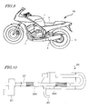
- FIG. 10 shows an exhaust gas cleaning system 200 disclosed in Pamphlet of International Publication No. 2004/113696.
- the exhaust gas cleaning system 200 includes an engine 201 and an exhaust pipe 207 connected to an exhaust port of the engine 201.
- a first catalyst 202A and a second catalyst 202B located downstream with respect to the first catalyst 202A are provided in the exhaust pipe 207.
- a secondary air introduction pipe 203 for introducing secondary air is connected to a portion of the exhaust pipe 207, the portion being between the first catalyst 202A and the second catalyst 202B.
- the first catalyst 202A and the second catalyst 202B have, for example, the same components as a known three-way catalyst.
- the engine 201 is driven at a fuel-rich side air/fuel ratio.
- Exhaust gas discharged from the engine 201 first contacts the first catalyst 202A.
- a three-way catalyst provides a high NO x cleaning ratio with a fuel-rich side air/fuel ratio. Therefore, NO x in the exhaust gas is removed by the first catalyst 202A until a required final cleaning ratio is achieved. At this point, CO and HC in the exhaust gas are also partially removed.
- the secondary air introduced from the secondary air introduction pipe 203 is mixed with the exhaust gas which has passed the first catalyst 202A, and thus the air/fuel ratio of the exhaust gas is shifted to a fuel-lean side.
- the exhaust gas of a fuel-lean side air/fuel ratio contacting the second catalyst 202B the CO and HC in the exhaust gas which have not been removed are now removed.
- this system first causes the exhaust gas to contact the first catalyst 202A under a reducing atmosphere to remove mainly NO x and then causes the exhaust gas to contact the second catalyst 202B under an oxidizing atmosphere to remove the remaining CO and HC.
- CO, HC and NO x in the exhaust gas can be removed highly efficiently.
- the exhaust gas cleaning system 200 described in Pamphlet of International Publication No. 2004/113696 allows the air/fuel ratio of the mixed gas supplied to the engine 201 to be smaller than the stoichiometric air/fuel ratio (i.e., to be set on the fuel-rich side). Therefore, the engine output of a saddle-riding type vehicle having a relatively small displacement can be improved to enhance the drivability thereof.
- this system functions sufficiently with the carburetor system used for generating mixed gas, which is advantageous over the injection system in terms of the cost.
- the present invention has been made in view of the above problems, and an objective thereof is to improve the NO x cleaning ratio in a saddle-riding type vehicle including an internal combustion engine causing combustion at an air/fuel ratio smaller than a stoichiometric air/fuel ratio.
- a saddle-riding type vehicle comprises: an internal combustion engine causing combustion at an air/fuel ratio smaller than a stoichiometric air/fuel ratio; a first catalyst provided in an exhaust path to which combustion gas is discharged from the internal combustion engine; a second catalyst provided in the exhaust path downstream with respect to the first catalyst; and a secondary air introduction device for introducing secondary air to a portion of the exhaust path, the portion being between the first catalyst and the second catalyst, wherein, the first catalyst and the second catalyst each contain a precious metal component containing at least one of Pt, Rh, Pd, and Au; and the first catalyst further contains a zeolite carrier and Co or Fe being carried on the zeolite carrier in an amount which is greater than an ion-exchangeable amount thereof.
- a carried amount of Co or Fe on the zeolite carrier is equal to or greater than twice the ion-exchangeable amount thereof.
- a carried amount of Co or Fe on the zeolite carrier is 25wt% or less.
- a carried amount of Co or Fe on the zeolite carrier is 20wt% or less.
- the first catalyst contains Rh in a carried amount of 0.2g/L or more.
- the internal combustion engine causes combustion at an air/fuel ratio of no less than 12.5 and no more than 14.5.
- the saddle-riding type vehicle according to the present invention further comprises a muffler, wherein the first catalyst and the second catalyst are located in the muffler.
- the first catalyst is distant from the internal combustion engine by 500 mm or more along the exhaust path.
- a saddle-riding type vehicle includes, in an exhaust path, a first catalyst and a second catalyst provided downstream with respect to the first catalyst, and also includes a secondary air introduction device for introducing secondary air in a portion of the exhaust path, the portion being between the first catalyst and the second catalyst.
- Combustion gas exhaust gas
- Combustion gas discharged from the internal combustion engine, causing combustion at an air/fuel ratio smaller than a stoichiometric air/fuel ratio, first contacts the first catalyst and, after being mixed with the secondary air introduced by the secondary air introduction device, contacts the second catalyst.
- the first catalyst and the second catalyst each contain a precious metal component containing at least one of Pt, Rh, Pd, and Au.
- the first catalyst of the saddle-riding type vehicle according to the present invention contains Co or Fe and a zeolite carrier carrying Co or Fe. Co and Fe function as catalysts for decomposing ammonia (NH 3 ).
- the zeolite carrier functions not only as a carrier of Co and Fe, but also as a promoter when decomposing ammonia.
- the first catalyst includes an ammonia decomposing component, NH 3 generated by the precious metal component in the first catalyst as a result of reducing NO x can be decomposed, and so the generation of NO x by the second catalyst can be suppressed.
- the NO x cleaning ratio can be improved. Furthermore, according to the present invention, since Co or Fe which is an ammonia decomposing component is carried on a zeolite carrier in an amount greater than the ion-exchangeable amount, Co or Fe is present in the zeolite carrier in a highly active zero-valent state. As a result, the NO x cleaning ratio is further improved. Since the internal combustion engine of the saddle-riding type vehicle according to the present invention causes combustion at an air/fuel ratio smaller than a stoichiometric air/fuel ratio (i.e., at a fuel-rich side air/fuel ratio), a high output is obtained and the drivability is improved. Hence, the saddle-riding type vehicle according to the present invention is superb both in the running performance and the environmental performance.
- the present invention can improve the NO x cleaning ratio in a saddle-riding type vehicle including an internal combustion engine causing combustion at an air/fuel ratio smaller than a stoichiometric air/fuel ratio.
- FIG. 1 A diagram schematically showing the construction of an exhaust gas cleaning system included in a saddle-riding type vehicle in a preferable embodiment of the present invention.
- FIG. 2 A diagram schematically showing the structure of a zeolite.
- FIG. 3 A graph showing a relationship between the amount of Co carried on a zeolite carrier and the generated amount of NO x .
- FIG. 4 A diagram schematically showing how Co may be carried on a zeolite carrier, in the case where the carried amount of Co is equal to or less than an ion-exchangeable amount thereof.
- FIG. 5 A diagram schematically showing how Co may be carried on a zeolite carrier, in the case where the carried amount of Co is greater than an ion-exchangeable amount thereof.
- FIG. 6 A graph showing a relationship between a carried amount of Co (wt%) on a zeolite carrier and an NO x cleaning ratio, with respect to Examples 1 to 4 and Comparative Examples 1 and 2.
- FIG. 7 A graph showing a relationship between the NO x concentration, NH 3 concentration, and the temperature of a first catalyst in exhaust gas which has passed the first catalyst.
- FIG. 8 A diagram schematically showing the construction of an exhaust gas cleaning system included in a saddle-riding type vehicle according to a preferable embodiment of the present invention.
- FIG. 9 A diagram showing an example of a motorcycle including an exhaust gas cleaning system as shown in FIG. 1 or FIG. 8 .
- FIG. 10 A diagram schematically showing the construction of a conventional exhaust gas cleaning system.
- FIG. 1 schematically shows the construction of an exhaust gas cleaning system included in a saddle-riding type vehicle in the present embodiment.
- the saddle-riding type vehicle in this embodiment includes an internal combustion engine 1, a first catalyst 2A and a second catalyst 2B, and a secondary air introduction device 3.
- the internal combustion engine (typically, gasoline engine) 1 causes combustion at an air/fuel ratio smaller than a stoichiometric air/fuel ratio. Since the combustion is caused at an air/fuel ratio smaller than the stoichiometric air/fuel ratio, i.e., a fuel-rich side air/fuel ratio, a higher output is obtained than in the case where the combustion is caused at the stoichiometric air/fuel ratio. Typically, the combustion is caused at an air/fuel ratio of no less than 12.5 and no more than 14.5.
- the internal combustion engine 1 is supplied with mixed gas from a carburetor 4 via an intake path 5a .
- the intake path 5a is a space enclosed by an intake pipe 5 connected to an intake port of the internal combustion engine 1.
- An air cleaner 6 is provided upstream with respect to the carburetor 4.
- the first catalyst 2A is provided in an exhaust path 7a to which combustion gas is discharged from the internal combustion engine 1.
- the second catalyst 2B is provided in the exhaust path 7a downstream with respect to the first catalyst 2A.
- the exhaust path 7a is a space enclosed by an exhaust pipe 7 connected to an exhaust port of the internal combustion engine 1.
- the secondary air introduction device 3 introduces secondary air to a portion 7a' of the exhaust path 7, the portion 7a' being between the first catalyst 2A and the second catalyst 2B.
- the secondary air introduction device 3 includes, for example, a secondary air introduction pipe 3a connected to the exhaust pipe 7 and a lead valve 3b provided between the secondary air introduction pipe 3a and the air cleaner 6.
- the lead valve 3b acts as a check valve for preventing a reverse flow of the secondary air supplied from the air cleaner 6 to the secondary air introduction pipe 3a.
- the secondary air introduction device 3 may have any construction which can introduce the secondary air to a portion between the first catalyst 2A and the second catalyst 2B, and is not limited to having a construction shown herein.
- a muffler 8 for reducing exhaust noise is connected to a downstream end of the exhaust pipe 7.
- the first catalyst 2A and the second catalyst 2B each contain a precious metal component.
- the precious metal component specifically contains at least one of platinum (Pt), rhodium (Rh), palladium (Pd) and gold (Au).
- the precious metal component of each of the first catalyst 2A and the second catalyst 2B oxidizes CO and HC, and reduces NO x , in the combustion gas (exhaust gas) discharged from the internal combustion engine 1, thus cleaning the combustion gas.
- the first catalyst 2A of the exhaust gas cleaning system in the present embodiment contains cobalt (Co) or iron (Fe) and a zeolite as a carrier for carrying Co or Fe ("zeolite carrier").
- Co and Fe function as catalysts for decomposing ammonia (NH 3 ).
- the zeolite carrier functions not only as a carrier of Co or Fe, but also as a promoter when decomposing ammonia.
- the first catalyst 2A contains an ammonia decomposing component.
- the exhaust gas cleaning system in the present embodiment can clean the exhaust gas from the internal combustion engine 1, which causes combustion at a fuel-rich side air/fuel ratio, at a high efficiency.
- the exhaust gas cleaning system in the present embodiment can prevent the generation of NO x derived from NH 3 , and thus can improve the final NO x cleaning ratio.
- the reason for this will be described specifically.
- Table 1 shows reactions caused by each of the first catalyst 202A and the second catalyst 202B in the conventional exhaust gas cleaning system 200.
- the second catalyst 202B As represented by chemical equations (6) and (7), the remaining CO and HC are removed. Specifically, as respectively represented by chemical equations (6) and (7), CO and HC react with the oxygen in the introduced secondary air, and are thus oxidized to generate CO 2 , or CO 2 and H 2 O. By the second catalyst 202B, as represented by chemical equation (8), NH 3 is oxidized to undesirably generate NO x .
- NO x is reduced into N 2 and also NH 3 by the first catalyst 202A, and NH 3 is oxidized by the second catalyst 202B to generate NO x . Therefore, the NO x cleaning ratio cannot be made sufficiently high.
- Table 2 shows reactions caused by each of the first catalyst 2A and the second catalyst 2B in the exhaust gas cleaning system in the present embodiment.
- the second catalyst 2B causes removal of the remaining CO and HC as represented by chemical equations (6) and (7), the NH 3 oxidation reaction as represented by chemical equation (8) in Table 1 decreases. Therefore, the generation of NO x is suppressed.
- the exhaust gas cleaning system in the present embodiment decomposes NH 3 (i.e., NH 3 generated as a result of reduction of NO x ) with the ammonia decomposing component contained in the first catalyst 2A. Since the generated amount of NH 3 is decreased by the first catalyst 2A in advance, generation of NO x by the second catalyst 2B is suppressed, whereby the NO x cleaning ratio is improved.
- NH 3 i.e., NH 3 generated as a result of reduction of NO x
- the first catalyst 2A of the exhaust gas cleaning system in the present embodiment contains Co or Fe as an ammonia decomposing component.
- Co and Fe allow the ammonia decomposition reaction represented by chemical equation (5) to occur efficiently under a reducing atmosphere.
- the zeolite carrier can promote the ammonia decomposition reaction by Co or Fe (chemical equation (5)).
- a zeolite having a silica/alumina ratio (SiO 2 /Al 2 O 3 ratio) of 10 mol/mol or more can be suitably used.
- an MFI-, FAU-, BEA-, or MOR-type zeolite can be suitably used.
- an MOR (mordenite) type zeolite those under the HSZ-600 series manufactured by TOSOH CORPORATION can be used, for example.
- Co or Fe is carried on the zeolite carrier in an amount which is greater than its ion-exchangeable amount.
- an "ion-exchangeable amount" is the maximum amount of Co or Fe which can be taken into the zeolite through an ion exchange reaction as described below.
- the NO x cleaning ratio is further improved because the first catalyst 2A contains Co or Fe being carried on the zeolite carrier in an amount which is greater than its ion-exchangeable amount. The reasons thereof will be described in detail below.
- a zeolite is a crystal of aluminosilicate having micropores within the crystal.
- a zeolite has a silicon dioxide backbone as its fundamental structure, such that the entire crystal lattice is negatively charged because some of the silicon is replaced by aluminum. Therefore, within its micropores, a zeolite contains cations (positive ions), e.g., sodium, thus maintaining an electric charge balance.
- cations positive ions
- sodium sodium
- a zeolite In the case where a zeolite is used as a carrier of a catalyst metal, the above ion exchange reaction is generally utilized to allow the catalyst metal to be taken into the zeolite. Therefore, when Co or Fe is carried on a zeolite carrier (i.e., taken into its micropores as Co 2+ , Fe 2+ ), usually, these elements will not be carried in an amount exceeding the ion-exchangeable amount.
- the first catalyst 2A of the exhaust gas cleaning system in the present embodiment contains Co or Fe being carried on the zeolite carrier in an amount which is greater than its ion-exchangeable amount.
- FIG. 3 shows an exemplary relationship between the amount of Co carried on a zeolite carrier and the generated amount of NO x .
- FIG. 3 illustrates a case where the ion-exchangeable amount of the zeolite carrier with respect to Co is about 2.4wt%.
- the Co carried on the zeolite carrier all exists as divalent cations (Co 2+ ) which have been taken into the micropores through ion exchange. Since Co 2+ is stable in this state, there is a low activity.
- the Co carried on the zeolite carrier includes not only the Co 2+ which has been taken into the micropores via ion exchange, but also zero-valent Co (Co°) which is carried at portions other than the micropores without undergoing ion exchange. Since the activity of Co° is higher than the activity of Co 2+ , the ammonia decomposition reaction is promoted as compared to the case where only Co 2+ exists, and thus the NO x cleaning ratio is improved.
- FIG. 4 and FIG. 5 illustrate exemplary backbones of an MOR (mordenite) type zeolite.
- MOR memory oxide
- FIG. 4 and FIG. 5 illustrate exemplary backbones of an MOR (mordenite) type zeolite.
- the backbone of a zeolite actually has a three-dimensional gridlike structure, it is shown in simplified forms in FIG. 4 and FIG. 5 .
- the NO x cleaning ratio can be improved also with Fe for a similar reason, because of the carried amount being greater than the ion-exchangeable amount.
- a method for allowing Co (or Fe) to be carried on the zeolite carrier in an amount which is greater than the ion-exchangeable amount for example, a method which is obtained by modifying the usual ion exchange-based carrying method (ion exchange technique) as follows can be used.
- ion exchange technique ion exchange technique
- ion-exchangeable amount [mol] amount of cations in zeolite [mol]/2.
- the amount of substance of Al ions is equal to the amount of substance of any monovalent cation in the zeolite
- the ion-exchangeable amount with respect to Co or Fe of 1 g of zeolite is 0.000833/2 ⁇ 0.00042 mol.
- this ion-exchangeable amount When expressed in terms of wt% of Co or Fe with respect to the zeolite carrier (that contains Co or Fe), this ion-exchangeable amount is 2.39549wt% for Co, and 2.272823wt% for Fe. That is, in the case where a zeolite whose silica/alumina ratio is 40 mol/mol is used as a carrier, the ion-exchangeable amount (wt%) is about 2.40wt% for Co, and about 2.27wt% for Fe.
- the NO x cleaning ratio can be greatly improved.
- the effect of decreasing the generated amount of NO x becomes higher as there is a larger carried amount of Co (or Fe) on the zeolite carrier. Therefore, from the standpoint of sufficiently decreasing the generated amount of NO x , it is preferable that the carried amount of Co (or Fe) is equal to or greater than twice the ion-exchangeable amount.
- the carried amount of Co (or Fe) on the zeolite carrier exceeds a certain amount, the generated amount of NO x will hardly change; that is, the effect of improving the NO x cleaning ratio will be saturated. Therefore, if the carried amount of Co (or Fe) is made excessive, there will be an increased amount of Co (or Fe) that does not contribute to the decomposition of NH 3 . Moreover, if the carried amount of Co (or Fe) is made excessive, the thermal resistance may be deteriorated. Therefore, from the standpoint of reducing the production cost and ensuring a thermal resistance, the carried amount of Co (or Fe) is preferably 25wt% or less, and more preferably 20wt% or less.
- the first catalyst 2A contains Rh such that the carried amount of Rh is 0.2 g/L or more.
- Exhaust gas cleaning systems of Examples 1 to 7 and Comparative Examples 1 to 3 were produced as follows.
- Examples 1 to 6 are exhaust gas cleaning systems according to the present embodiment, where Co is contained in the first catalyst 2A as an ammonia decomposing component in an amount which is greater than the ion-exchangeable amount.
- Example 7 is an exhaust gas cleaning system according to the present embodiment, where Fe is contained in the first catalyst 2A as an ammonia decomposing component in an amount which is greater than the ion-exchangeable amount.
- the exhaust gas cleaning system of Comparative Example 1 does not contain any Co or Fe, i.e., ammonia decomposing component, in the first catalyst (upstream catalyst).
- Co is contained in the first catalyst (upstream catalyst) in an amount which is smaller than the ion-exchangeable amount.
- an alumina carrier is contained in the first catalyst instead of a zeolite carrier.
- the coated metal honeycomb was immersed in 300 g of distilled water to which dinitro diamine platinum and rhodium nitrate had been added, and left for a predetermined period of time, thus allowing Pt and Rh to adsorb to the surface of the metal honeycomb. Thereafter, the metal honeycomb was dried at 120°C, and baked at 600°C, whereby a metal honeycomb carrying 1.0 g/L of Pt and 0.5 g/L of Rh was obtained. In this manner, a first catalyst 2A containing precious metal components, a zeolite carrier, and Co being carried on the zeolite carrier in an amount greater than the ion-exchangeable amount was produced.
- oxidation catalyst material Pt1.0 g/L, Rh0.5 g/L
- the first catalyst 2A was attached at an upstream portion of the exhaust path 7a, and the second catalyst 2B was attached at a downstream portion of the exhaust path 7a, thus producing an exhaust gas cleaning system having the construction as shown in FIG. 1 .
- An exhaust gas cleaning system was produced in a similar manner to Example 1, except that the amount of cobalt nitrate hexahydrate used when producing the first catalyst 2A was 9.3 g.
- the first catalyst 2A contained 4wt% Co-zeolite.
- An exhaust gas cleaning system was produced in a similar manner to Example 1, except that the amount of cobalt nitrate hexahydrate used when producing the first catalyst 2A was 19.3 g.
- the first catalyst 2A contained 8wt% Co-zeolite.
- An exhaust gas cleaning system was produced in a similar manner to Example 1, except that the amount of cobalt nitrate hexahydrate used when producing the first catalyst 2A was 55.6 g.
- the first catalyst 2A contained 20wt% Co-zeolite.
- An exhaust gas cleaning system was produced in a similar manner to Example 1, except that the carried amount of Rh when producing the first catalyst 2A was 0 g/L (whereas the carried amount of Pt was still 1.0 g/L).
- An exhaust gas cleaning system was produced in a similar manner to Example 1, except that the carried amount of Rh when producing the first catalyst 2A was 0.2 g/L (whereas the carried amount of Pt was still 1.0 g/L).
- An exhaust gas cleaning system was produced in a similar manner to Example 1, except that, instead of 24.7 g of cobalt nitrate hexahydrate, 34.3 g of iron nitrate (III) nonahydrate was used when producing the first catalyst 2A.
- the first catalyst 2A contained 10wt% Fe-zeolite.
- An exhaust gas cleaning system was produced in a similar manner to Example 1, except that the amount of cobalt nitrate hexahydrate used when producing the first catalyst 2A was 0 g.
- the first catalyst 2A contained a zeolite, but contained neither Co nor Fe.
- An exhaust gas cleaning system was produced in a similar manner to Example 1, except that the amount of cobalt nitrate hexahydrate used when producing the first catalyst 2A was 4.5 g.
- the first catalyst 2A contained 2wt% Co-zeolite.
- An exhaust gas cleaning system was produced in a similar manner to Example 1, except that, instead of an MFI-type zeolite, ⁇ alumina was used when producing the first catalyst 2A.
- the first catalyst 2A contained 10wt% Co- ⁇ alumina.
- Table 4 shows results of, with respect to Examples 1 to 7 and Comparative Examples 1 to 3, attaching each prototyped exhaust gas cleaning system to a motorcycle having a displacement of 125cc, whose A/F was set in a range from 13.0 to 14.0, and measuring the NO x cleaning ratio while the motorcycle traveled in the ECE40 mode.
- the "carried amount of Co (carried amount of Fe)" column of Table 4 describes not only the carried amount (wt%) of Co(Fe) on the carrier (zeolite or alumina), but also the carried amount (g/L) of Co(Fe) in the entire first catalyst.
- the “carrier of Co (carrier of Fe)” column describes not only what the carrier of Co (carrier of Fe) is, but also the carried amount (g/L) of the carrier of Co (carrier of Fe) in the entire first catalyst.
- the "judgment” column indicates “ ⁇ ” if the NO x cleaning ratio is very high (specifically, 70% or more); “ ⁇ ” if it is sufficiently high (specifically, no less than 55% but less than 70%); and “ ⁇ ” if it is not sufficiently high (specifically, less than 55%).
- FIG. 6 shows a relationship between the carried amount of Co (wt%) on the zeolite carrier and the NO x cleaning ratio, with respect to Examples 1 to 4 and Comparative Examples 1 and 2.
- Example 4 precious metal component carried amount of Co (carried amount of Fe) carrier of Co (carrier of Fe) NO x cleaning ratio judg- ment Pt(g/L) Rh(g/L)
- Example 1 1.0 0.5 10wt% (2.5 g/L) MFI zeolite (22.5 g/L) 72% ⁇
- Example 2 1.0 0.5 4wt% (1.0 g/L) MFI zeolite (24.0 g/L) 59% ⁇
- Example 3 1.0 0.5 8wt% (2.0 g/L) MFI zeolite (23.0 g/L) 70% ⁇
- Example 4 1.0 0.5 20wt% (5.0 g/L) MFI zeolite (20.0 g/L) 74% ⁇
- Example 5 1.0 0 10wt% (2.5 g/L) MFI zeolite (22.5 g/L) 61% ⁇
- Example 6 1.0 0.2 10wt% (2.5 g/L) MFI zeo
- Example 1 1.0 0.5 0 MFI zeolite (25.0 g/L) 53% ⁇ Comp.
- Example 2 1.0 0.5 2wt% (0.5 g/L) MFI zeolite (24.5 g/L) 52% ⁇ Comp.
- Example 3 1.0 0.5 10wt% (2.5 g/L) ⁇ alumina (22.5 g/L) 53% ⁇
- a comparison between Examples 1 to 7 and Comparative Examples 1 and 2 indicates that the NO x cleaning ratio is improved in Examples 1 to 7 (in which Co or Fe is carried on the zeolite carrier in an amount greater than the ion-exchangeable amount), as compared to Comparative Example 1 (in which no Co or Fe is contained) and Comparative Example 2 (in which Co is carried in an amount smaller than the ion-exchangeable amount). Moreover, a comparison between Examples 1, 3, 4, and 6 and Example 2 indicates that the NO x cleaning ratio is further improved when the carried amount of Co is greater than twice the ion-exchangeable amount.
- Example 1 and 6 indicates that it is preferable for the first catalyst 2A to contain Rh in a carried amount of 0.2 g/L or more.
- Example 1 and Comparative Example 3 indicates that it is preferable to use a zeolite as a Co carrier, rather than alumina.
- the exhaust gas cleaning system according to the present embodiment can highly efficiently remove NO x in the combustion gas which is discharged from an internal combustion engine causing combustion at an air/fuel ratio smaller than a stoichiometric air/fuel ratio.
- the NH 3 which is generated by the first catalyst 2A located upstream is decomposed by an ammonia decomposing component contained in the first catalyst 2A.
- a construction would be possible in which not only an upstream catalyst but also a downstream catalyst (e.g., the second catalyst 202B of the exhaust gas cleaning system 200 shown in FIG. 10 ) contains an ammonia decomposing component.
- oxidation of NH 3 , CO and HC would occur substantially simultaneously under an oxidizing atmosphere, so that NH 3 would tend to be over-oxidized, thus allowing NO x to occur.
- the cleaning ratios of CO and HC would not be made sufficiently high, thus making it necessary to add still other oxidation catalysts as a compliment, thus resulting in an increased production cost.
- the first catalyst 2A contains an ammonia decomposing component, removal of NO x and decomposition of NH 3 can simultaneously occur under a reducing atmosphere, so that the aforementioned problem does not occur.
- the first catalyst 2A contains an ammonia decomposing component so that a sufficiently high NO x cleaning ratio can be realized at a lower temperature than conventionally. That is, the exhaust gas cleaning system in the present embodiment is preferably usable even at a lower temperature than conventionally.
- FIG. 7 is a graph showing, with respect to the exhaust gas cleaning system in the present embodiment and the conventional exhaust gas cleaning system 200, a relationship between NO x concentration and NH 3 concentration in the exhaust gas which has passed the first catalyst, and temperature of the first catalyst.
- the NH 3 concentration is high, thus resulting in a low final NO x cleaning ratio.
- the NH 3 concentration can be made sufficiently low at 550°C or above, so that the final NO x cleaning ratio can be made sufficiently high. Therefore, whereas the conventional exhaust gas cleaning system has a temperature range of use of 650°C to 900°C (arrow A in FIG. 7 ), the temperature range of use of the exhaust gas cleaning system in the present embodiment is 550°C to 900°C (arrow B in FIG. 7 ). The reason why the upper limit of the temperature range of use is 900°C in either case is that it becomes difficult to maintain durability of the catalysts at 900°C or above.
- the first catalyst 202A is placed somewhat near the engine 1 so that the temperature of the first catalyst 202A will be rapidly increased.
- the first catalyst 2A can be located at a position farther from the internal combustion engine 1 than conventionally.
- the first catalyst 202A is located at a position 150 mm to 400 mm away from the engine 201.
- the first catalyst 2A can be located at a position 150 mm to 600 mm away from the internal combustion engine 1.
- the distance from an internal combustion engine to a muffler is about 500 mm.
- the first catalyst 2A can be located away from the internal combustion engine 1 along the exhaust path 7a by 500 mm or more. Therefore, as shown in FIG. 8 , both of the first catalyst 2A and the second catalyst 2B can be located in the muffler 8.
- An area around the first catalyst 2A and an area around the second catalyst 2B have a high temperature because of the reaction heat caused by the cleaning reactions. Locating (accommodating) the first catalyst 2A and the second catalyst 2B in the muffler 8 as shown in FIG. 8 prevents peripheral elements from being softened or deteriorated (heat-damaged). Moreover, since there is no need to employ a thick exhaust pipe 7 in order to accommodate the first catalyst 2A and the second catalyst 2B, the layout of the exhaust pipe 7 is facilitated, whereby advantages in the external appearance (improvement of design, etc.) are also provided.
- FIG. 9 shows a motorcycle 100 including the exhaust gas cleaning system in the present embodiment.
- the motorcycle 100 includes the engine (e.g., a 4-stroke gasoline engine) 1 which is located frontward of a seat 11 on which the rider sits, the exhaust pipe 7 which is connected to the exhaust port of the engine 1, and the muffler 8 which is connected to the exhaust pipe 7 and provided near the rear wheel 12.
- the first catalyst 2A and the second catalyst 2B are provided in the exhaust pipe 7, although not shown.
- the motorcycle 100 further includes the secondary air introduction device 3 for introducing secondary air to the exhaust pipe 7.
- the engine 1 is driven at a fuel-rich side air/fuel ratio. Therefore, a high engine output is obtained and a high drivability is realized.
- the motorcycle 100 includes the above-described exhaust gas cleaning system and so can highly efficiently clean NO x contained in the exhaust gas from the engine 1 driven at a fuel-rich side air/fuel ratio. As a result, the motorcycle 100 is superb both in the running performance and the environmental performance.
- the carburetor 4 is provided (carburetor system) as an example.
- the motorcycle 100 may have a construction including an injector (namely, mixed gas may be generated by the injection system).
- the exhaust gas cleaning system in the present embodiment is not limited to being used in motorcycles and is suitably usable in any saddle-riding type vehicle on which a rider may sit astraddle.
- the exhaust gas cleaning system in the present embodiment is usable for ATVs such as buggies.
- a saddle-riding type vehicle generally has a small displacement and so it is preferable that the internal combustion engine thereof is driven at a fuel-rich side air/fuel ratio. Therefore, it is highly meaningful to mount the exhaust gas cleaning system in the present embodiment.
- the present invention can improve the NOx cleaning ratio in a saddle-riding type vehicle including an internal combustion engine causing combustion at an air/fuel ratio smaller than a stoichiometric air/fuel ratio.
Landscapes
- Engineering & Computer Science (AREA)
- Chemical & Material Sciences (AREA)
- Chemical Kinetics & Catalysis (AREA)
- Combustion & Propulsion (AREA)
- Mechanical Engineering (AREA)
- General Engineering & Computer Science (AREA)
- Health & Medical Sciences (AREA)
- Toxicology (AREA)
- Biomedical Technology (AREA)
- Environmental & Geological Engineering (AREA)
- Analytical Chemistry (AREA)
- General Chemical & Material Sciences (AREA)
- Oil, Petroleum & Natural Gas (AREA)
- Materials Engineering (AREA)
- Exhaust Gas After Treatment (AREA)
- Catalysts (AREA)
- Exhaust Gas Treatment By Means Of Catalyst (AREA)
Applications Claiming Priority (1)
| Application Number | Priority Date | Filing Date | Title |
|---|---|---|---|
| JP2009074888A JP5306871B2 (ja) | 2009-03-25 | 2009-03-25 | 鞍乗り型車両 |
Publications (3)
| Publication Number | Publication Date |
|---|---|
| EP2233197A2 true EP2233197A2 (fr) | 2010-09-29 |
| EP2233197A3 EP2233197A3 (fr) | 2010-11-10 |
| EP2233197B1 EP2233197B1 (fr) | 2014-01-22 |
Family
ID=42286730
Family Applications (1)
| Application Number | Title | Priority Date | Filing Date |
|---|---|---|---|
| EP09176627.9A Active EP2233197B1 (fr) | 2009-03-25 | 2009-11-20 | Véhicule à monture |
Country Status (4)
| Country | Link |
|---|---|
| EP (1) | EP2233197B1 (fr) |
| JP (1) | JP5306871B2 (fr) |
| CN (1) | CN101845981A (fr) |
| ES (1) | ES2449595T3 (fr) |
Cited By (5)
| Publication number | Priority date | Publication date | Assignee | Title |
|---|---|---|---|---|
| CN104005823A (zh) * | 2014-06-06 | 2014-08-27 | 四川中自尾气净化有限公司 | 一种用于摩托车尾气处理的催化转化器及其制备方法 |
| US9517434B2 (en) | 2012-02-15 | 2016-12-13 | Toyota Jidosha Kabushika Kaisha | Catalyst system for exhaust gas purification utilizing base metals, and controlling method therefor |
| WO2018224064A1 (fr) * | 2017-06-06 | 2018-12-13 | Christian Koch | Catalyseur à trois voies |
| EP3511541A1 (fr) * | 2018-01-15 | 2019-07-17 | AM Group Redback AB | Convertisseur catalytique pour voitures classiques |
| CN117899925A (zh) * | 2024-01-17 | 2024-04-19 | 江苏金胜机车部件有限公司 | 一种低铑型的摩托车三元催化触媒及其制备方法 |
Families Citing this family (6)
| Publication number | Priority date | Publication date | Assignee | Title |
|---|---|---|---|---|
| CN102465731B (zh) * | 2010-11-05 | 2016-05-04 | 常州光阳摩托车有限公司 | 内燃机的尾气净化消声器 |
| DE102015219113A1 (de) * | 2015-10-02 | 2017-04-06 | Volkswagen Ag | Verfahren und Vorrichtung zur Abgasnachbehandlung eines Verbrennungsmotors |
| CN107345494A (zh) * | 2016-05-06 | 2017-11-14 | 上汽通用汽车有限公司 | 一种汽车尾气排放后处理系统 |
| DE102017115399A1 (de) | 2017-07-10 | 2019-01-10 | Volkswagen Ag | Abgasnachbehandlungssystem und Verfahren zur Abgasnachbehandlung eines Verbrennungsmotors |
| KR101977009B1 (ko) * | 2019-02-07 | 2019-05-09 | 정종구 | 매연 저감장치 |
| JP7742604B2 (ja) * | 2021-07-30 | 2025-09-22 | 太平洋セメント株式会社 | 水素の製造方法、アンモニア含有ガスの処理材および処理材の製造方法 |
Citations (3)
| Publication number | Priority date | Publication date | Assignee | Title |
|---|---|---|---|---|
| US20060101813A1 (en) | 2004-07-13 | 2006-05-18 | Wu Hsiao C | Muffler device with catalysts for improving purifying exhaust gas of nitrogen oxides within a motorcycle exhaust pipe |
| WO2008036908A2 (fr) | 2006-09-21 | 2008-03-27 | Basf Catalysts Llc | Systèmes et procédés de traitement pour des flux d'échappement de moteur à combustion interne |
| US20080292519A1 (en) | 2007-02-27 | 2008-11-27 | Caudle Matthew T | Bifunctional Catalysts for Selective Ammonia Oxidation |
Family Cites Families (7)
| Publication number | Priority date | Publication date | Assignee | Title |
|---|---|---|---|---|
| JPH05168942A (ja) * | 1991-12-20 | 1993-07-02 | Toyota Central Res & Dev Lab Inc | 窒素酸化物浄化触媒 |
| US7229597B2 (en) * | 2003-08-05 | 2007-06-12 | Basfd Catalysts Llc | Catalyzed SCR filter and emission treatment system |
| JP2006037891A (ja) * | 2004-07-29 | 2006-02-09 | Sentec E & E Co Ltd | オートバイのマフラーの排気通路内において触媒の浄化、窒酸化を高める方法。 |
| JP2007245050A (ja) * | 2006-03-17 | 2007-09-27 | Toyota Central Res & Dev Lab Inc | 窒素酸化物吸着材、その製造方法、及びそれを用いた窒素酸化物の除去方法 |
| DE602008000554D1 (de) * | 2007-03-13 | 2010-03-11 | Yamaha Motor Co Ltd | Abgassystem und Verfahren zur Steuerung eines Motors eines Zweiradfahrzeugs |
| JP5110954B2 (ja) * | 2007-05-09 | 2012-12-26 | エヌ・イーケムキャット株式会社 | 選択還元型触媒を用いた排気ガス浄化触媒装置並びに排気ガス浄化方法 |
| BRPI0812314A2 (pt) * | 2007-05-30 | 2014-11-25 | Yamaha Motor Co Ltd | Dispositivo de exaustão e veículo do tipo de montar |
-
2009
- 2009-03-25 JP JP2009074888A patent/JP5306871B2/ja active Active
- 2009-11-20 EP EP09176627.9A patent/EP2233197B1/fr active Active
- 2009-11-20 ES ES09176627.9T patent/ES2449595T3/es active Active
- 2009-12-28 CN CN200910261146A patent/CN101845981A/zh active Pending
Patent Citations (3)
| Publication number | Priority date | Publication date | Assignee | Title |
|---|---|---|---|---|
| US20060101813A1 (en) | 2004-07-13 | 2006-05-18 | Wu Hsiao C | Muffler device with catalysts for improving purifying exhaust gas of nitrogen oxides within a motorcycle exhaust pipe |
| WO2008036908A2 (fr) | 2006-09-21 | 2008-03-27 | Basf Catalysts Llc | Systèmes et procédés de traitement pour des flux d'échappement de moteur à combustion interne |
| US20080292519A1 (en) | 2007-02-27 | 2008-11-27 | Caudle Matthew T | Bifunctional Catalysts for Selective Ammonia Oxidation |
Cited By (6)
| Publication number | Priority date | Publication date | Assignee | Title |
|---|---|---|---|---|
| US9517434B2 (en) | 2012-02-15 | 2016-12-13 | Toyota Jidosha Kabushika Kaisha | Catalyst system for exhaust gas purification utilizing base metals, and controlling method therefor |
| CN104005823A (zh) * | 2014-06-06 | 2014-08-27 | 四川中自尾气净化有限公司 | 一种用于摩托车尾气处理的催化转化器及其制备方法 |
| WO2018224064A1 (fr) * | 2017-06-06 | 2018-12-13 | Christian Koch | Catalyseur à trois voies |
| EP3511541A1 (fr) * | 2018-01-15 | 2019-07-17 | AM Group Redback AB | Convertisseur catalytique pour voitures classiques |
| US10605139B2 (en) | 2018-01-15 | 2020-03-31 | Am Group Redback Ab | Catalytic converter for classic cars |
| CN117899925A (zh) * | 2024-01-17 | 2024-04-19 | 江苏金胜机车部件有限公司 | 一种低铑型的摩托车三元催化触媒及其制备方法 |
Also Published As
| Publication number | Publication date |
|---|---|
| EP2233197A3 (fr) | 2010-11-10 |
| CN101845981A (zh) | 2010-09-29 |
| EP2233197B1 (fr) | 2014-01-22 |
| JP2010229817A (ja) | 2010-10-14 |
| JP5306871B2 (ja) | 2013-10-02 |
| ES2449595T3 (es) | 2014-03-20 |
Similar Documents
| Publication | Publication Date | Title |
|---|---|---|
| EP2233197A2 (fr) | Véhicule à monture | |
| JP5875586B2 (ja) | ディーゼルエンジンの排ガスから窒素酸化物を除去するための触媒 | |
| EP2113296A2 (fr) | Procédé de purification de gaz d'échappement utilisant un catalyseur de réduction sélectif | |
| EP0832688B1 (fr) | Catalyseur d'epuration de gaz d'echappement et procede d'epuration correspondant | |
| CN101588865B (zh) | 用于还原氧化氮的催化剂组合物 | |
| EP2431094A1 (fr) | Catalyseur pour la purification de gaz d'échappement | |
| KR101986388B1 (ko) | Egr 회로에서 암모니아 슬립 촉매를 가지는 배기 시스템 | |
| US20110258994A1 (en) | Bifunctional Catalyst for Decomposition and Oxidation of Nitrogen Monoxide, Composite Catalyst Including the Same for Apparatus to Decrease Exhaust Gas, and Method for Preparation Thereof | |
| JP5549656B2 (ja) | 内燃機関の排気浄化装置 | |
| EP0719580A1 (fr) | Dispositif et méthode pour la purification de gaz d'échappement | |
| EP3892837B1 (fr) | Dispositif de purge de gaz d'échappement | |
| CN100526618C (zh) | 用于改进机动车中NOx还原效率的方法 | |
| EP1797945A1 (fr) | Procédé pour la réduction catalytique des oxydes d'azote | |
| KR20200096016A (ko) | 일산화탄소 제거 촉매, 이를 사용한 후처리 장치, 그리고 후처리 방법 | |
| EP2169193A1 (fr) | Véhicule de type à selle | |
| WO2005023421A1 (fr) | Catalyseur et procede de decomposition d'oxyde d'azote par contact | |
| US20150337709A1 (en) | Exhaust gas processing apparatus and method | |
| KR20100134605A (ko) | 내연기관 배기 가스의 정화용 촉매 및 이 촉매를 사용한 배기 가스의 정화 방법 | |
| KR101571660B1 (ko) | 디젤 차를 포함하는 상용 차량을 위한 산화 촉매 | |
| EP2153896A1 (fr) | Catalyseur purificateur de NOx | |
| CN1215794A (zh) | 机动车湿法排气净化及其装置和净化液 | |
| TW200925394A (en) | Straddle-type vehicle | |
| EP2141333B1 (fr) | Appareil de purification de gaz d'échappement | |
| KR101274468B1 (ko) | 디젤엔진의 배기가스 정화용 산화촉매 | |
| US20180065087A1 (en) | Scr catalyst |
Legal Events
| Date | Code | Title | Description |
|---|---|---|---|
| PUAI | Public reference made under article 153(3) epc to a published international application that has entered the european phase |
Free format text: ORIGINAL CODE: 0009012 |
|
| AK | Designated contracting states |
Kind code of ref document: A2 Designated state(s): AT BE BG CH CY CZ DE DK EE ES FI FR GB GR HR HU IE IS IT LI LT LU LV MC MK MT NL NO PL PT RO SE SI SK SM TR |
|
| PUAL | Search report despatched |
Free format text: ORIGINAL CODE: 0009013 |
|
| AK | Designated contracting states |
Kind code of ref document: A3 Designated state(s): AT BE BG CH CY CZ DE DK EE ES FI FR GB GR HR HU IE IS IT LI LT LU LV MC MK MT NL NO PL PT RO SE SI SK SM TR |
|
| 17P | Request for examination filed |
Effective date: 20110509 |
|
| 17Q | First examination report despatched |
Effective date: 20120726 |
|
| RIC1 | Information provided on ipc code assigned before grant |
Ipc: B01D 53/94 20060101AFI20130318BHEP Ipc: F01N 3/30 20060101ALI20130318BHEP Ipc: F01N 3/28 20060101ALI20130318BHEP Ipc: F01N 3/10 20060101ALI20130318BHEP |
|
| GRAP | Despatch of communication of intention to grant a patent |
Free format text: ORIGINAL CODE: EPIDOSNIGR1 |
|
| INTG | Intention to grant announced |
Effective date: 20130913 |
|
| GRAS | Grant fee paid |
Free format text: ORIGINAL CODE: EPIDOSNIGR3 |
|
| GRAA | (expected) grant |
Free format text: ORIGINAL CODE: 0009210 |
|
| AK | Designated contracting states |
Kind code of ref document: B1 Designated state(s): AT BE BG CH CY CZ DE DK EE ES FI FR GB GR HR HU IE IS IT LI LT LU LV MC MK MT NL NO PL PT RO SE SI SK SM TR |
|
| RAP1 | Party data changed (applicant data changed or rights of an application transferred) |
Owner name: YAMAHA HATSUDOKI KABUSHIKI KAISHA |
|
| REG | Reference to a national code |
Ref country code: GB Ref legal event code: FG4D |
|
| REG | Reference to a national code |
Ref country code: CH Ref legal event code: EP |
|
| REG | Reference to a national code |
Ref country code: AT Ref legal event code: REF Ref document number: 650500 Country of ref document: AT Kind code of ref document: T Effective date: 20140215 |
|
| REG | Reference to a national code |
Ref country code: IE Ref legal event code: FG4D |
|
| REG | Reference to a national code |
Ref country code: DE Ref legal event code: R096 Ref document number: 602009021547 Country of ref document: DE Effective date: 20140306 |
|
| REG | Reference to a national code |
Ref country code: ES Ref legal event code: FG2A Ref document number: 2449595 Country of ref document: ES Kind code of ref document: T3 Effective date: 20140320 |
|
| REG | Reference to a national code |
Ref country code: NL Ref legal event code: VDEP Effective date: 20140122 |
|
| REG | Reference to a national code |
Ref country code: AT Ref legal event code: MK05 Ref document number: 650500 Country of ref document: AT Kind code of ref document: T Effective date: 20140122 |
|
| REG | Reference to a national code |
Ref country code: LT Ref legal event code: MG4D |
|
| PG25 | Lapsed in a contracting state [announced via postgrant information from national office to epo] |
Ref country code: IS Free format text: LAPSE BECAUSE OF FAILURE TO SUBMIT A TRANSLATION OF THE DESCRIPTION OR TO PAY THE FEE WITHIN THE PRESCRIBED TIME-LIMIT Effective date: 20140522 Ref country code: LT Free format text: LAPSE BECAUSE OF FAILURE TO SUBMIT A TRANSLATION OF THE DESCRIPTION OR TO PAY THE FEE WITHIN THE PRESCRIBED TIME-LIMIT Effective date: 20140122 Ref country code: NO Free format text: LAPSE BECAUSE OF FAILURE TO SUBMIT A TRANSLATION OF THE DESCRIPTION OR TO PAY THE FEE WITHIN THE PRESCRIBED TIME-LIMIT Effective date: 20140422 |
|
| PG25 | Lapsed in a contracting state [announced via postgrant information from national office to epo] |
Ref country code: AT Free format text: LAPSE BECAUSE OF FAILURE TO SUBMIT A TRANSLATION OF THE DESCRIPTION OR TO PAY THE FEE WITHIN THE PRESCRIBED TIME-LIMIT Effective date: 20140122 Ref country code: CY Free format text: LAPSE BECAUSE OF FAILURE TO SUBMIT A TRANSLATION OF THE DESCRIPTION OR TO PAY THE FEE WITHIN THE PRESCRIBED TIME-LIMIT Effective date: 20140122 Ref country code: NL Free format text: LAPSE BECAUSE OF FAILURE TO SUBMIT A TRANSLATION OF THE DESCRIPTION OR TO PAY THE FEE WITHIN THE PRESCRIBED TIME-LIMIT Effective date: 20140122 Ref country code: FI Free format text: LAPSE BECAUSE OF FAILURE TO SUBMIT A TRANSLATION OF THE DESCRIPTION OR TO PAY THE FEE WITHIN THE PRESCRIBED TIME-LIMIT Effective date: 20140122 Ref country code: PT Free format text: LAPSE BECAUSE OF FAILURE TO SUBMIT A TRANSLATION OF THE DESCRIPTION OR TO PAY THE FEE WITHIN THE PRESCRIBED TIME-LIMIT Effective date: 20140522 Ref country code: SE Free format text: LAPSE BECAUSE OF FAILURE TO SUBMIT A TRANSLATION OF THE DESCRIPTION OR TO PAY THE FEE WITHIN THE PRESCRIBED TIME-LIMIT Effective date: 20140122 |
|
| PG25 | Lapsed in a contracting state [announced via postgrant information from national office to epo] |
Ref country code: BE Free format text: LAPSE BECAUSE OF FAILURE TO SUBMIT A TRANSLATION OF THE DESCRIPTION OR TO PAY THE FEE WITHIN THE PRESCRIBED TIME-LIMIT Effective date: 20140122 Ref country code: LV Free format text: LAPSE BECAUSE OF FAILURE TO SUBMIT A TRANSLATION OF THE DESCRIPTION OR TO PAY THE FEE WITHIN THE PRESCRIBED TIME-LIMIT Effective date: 20140122 Ref country code: HR Free format text: LAPSE BECAUSE OF FAILURE TO SUBMIT A TRANSLATION OF THE DESCRIPTION OR TO PAY THE FEE WITHIN THE PRESCRIBED TIME-LIMIT Effective date: 20140122 |
|
| REG | Reference to a national code |
Ref country code: DE Ref legal event code: R097 Ref document number: 602009021547 Country of ref document: DE |
|
| PG25 | Lapsed in a contracting state [announced via postgrant information from national office to epo] |
Ref country code: CZ Free format text: LAPSE BECAUSE OF FAILURE TO SUBMIT A TRANSLATION OF THE DESCRIPTION OR TO PAY THE FEE WITHIN THE PRESCRIBED TIME-LIMIT Effective date: 20140122 Ref country code: DK Free format text: LAPSE BECAUSE OF FAILURE TO SUBMIT A TRANSLATION OF THE DESCRIPTION OR TO PAY THE FEE WITHIN THE PRESCRIBED TIME-LIMIT Effective date: 20140122 Ref country code: EE Free format text: LAPSE BECAUSE OF FAILURE TO SUBMIT A TRANSLATION OF THE DESCRIPTION OR TO PAY THE FEE WITHIN THE PRESCRIBED TIME-LIMIT Effective date: 20140122 Ref country code: RO Free format text: LAPSE BECAUSE OF FAILURE TO SUBMIT A TRANSLATION OF THE DESCRIPTION OR TO PAY THE FEE WITHIN THE PRESCRIBED TIME-LIMIT Effective date: 20140122 |
|
| PG25 | Lapsed in a contracting state [announced via postgrant information from national office to epo] |
Ref country code: PL Free format text: LAPSE BECAUSE OF FAILURE TO SUBMIT A TRANSLATION OF THE DESCRIPTION OR TO PAY THE FEE WITHIN THE PRESCRIBED TIME-LIMIT Effective date: 20140122 Ref country code: SK Free format text: LAPSE BECAUSE OF FAILURE TO SUBMIT A TRANSLATION OF THE DESCRIPTION OR TO PAY THE FEE WITHIN THE PRESCRIBED TIME-LIMIT Effective date: 20140122 |
|
| PLBE | No opposition filed within time limit |
Free format text: ORIGINAL CODE: 0009261 |
|
| STAA | Information on the status of an ep patent application or granted ep patent |
Free format text: STATUS: NO OPPOSITION FILED WITHIN TIME LIMIT |
|
| 26N | No opposition filed |
Effective date: 20141023 |
|
| REG | Reference to a national code |
Ref country code: DE Ref legal event code: R097 Ref document number: 602009021547 Country of ref document: DE Effective date: 20141023 |
|
| PG25 | Lapsed in a contracting state [announced via postgrant information from national office to epo] |
Ref country code: SI Free format text: LAPSE BECAUSE OF FAILURE TO SUBMIT A TRANSLATION OF THE DESCRIPTION OR TO PAY THE FEE WITHIN THE PRESCRIBED TIME-LIMIT Effective date: 20140122 |
|
| PG25 | Lapsed in a contracting state [announced via postgrant information from national office to epo] |
Ref country code: LU Free format text: LAPSE BECAUSE OF FAILURE TO SUBMIT A TRANSLATION OF THE DESCRIPTION OR TO PAY THE FEE WITHIN THE PRESCRIBED TIME-LIMIT Effective date: 20141120 Ref country code: MC Free format text: LAPSE BECAUSE OF FAILURE TO SUBMIT A TRANSLATION OF THE DESCRIPTION OR TO PAY THE FEE WITHIN THE PRESCRIBED TIME-LIMIT Effective date: 20140122 |
|
| REG | Reference to a national code |
Ref country code: CH Ref legal event code: PL |
|
| PG25 | Lapsed in a contracting state [announced via postgrant information from national office to epo] |
Ref country code: CH Free format text: LAPSE BECAUSE OF NON-PAYMENT OF DUE FEES Effective date: 20141130 Ref country code: LI Free format text: LAPSE BECAUSE OF NON-PAYMENT OF DUE FEES Effective date: 20141130 |
|
| REG | Reference to a national code |
Ref country code: IE Ref legal event code: MM4A |
|
| PG25 | Lapsed in a contracting state [announced via postgrant information from national office to epo] |
Ref country code: IE Free format text: LAPSE BECAUSE OF NON-PAYMENT OF DUE FEES Effective date: 20141120 |
|
| REG | Reference to a national code |
Ref country code: FR Ref legal event code: PLFP Year of fee payment: 7 |
|
| PG25 | Lapsed in a contracting state [announced via postgrant information from national office to epo] |
Ref country code: SM Free format text: LAPSE BECAUSE OF FAILURE TO SUBMIT A TRANSLATION OF THE DESCRIPTION OR TO PAY THE FEE WITHIN THE PRESCRIBED TIME-LIMIT Effective date: 20140122 |
|
| PG25 | Lapsed in a contracting state [announced via postgrant information from national office to epo] |
Ref country code: GR Free format text: LAPSE BECAUSE OF FAILURE TO SUBMIT A TRANSLATION OF THE DESCRIPTION OR TO PAY THE FEE WITHIN THE PRESCRIBED TIME-LIMIT Effective date: 20140423 Ref country code: BG Free format text: LAPSE BECAUSE OF FAILURE TO SUBMIT A TRANSLATION OF THE DESCRIPTION OR TO PAY THE FEE WITHIN THE PRESCRIBED TIME-LIMIT Effective date: 20140122 |
|
| PG25 | Lapsed in a contracting state [announced via postgrant information from national office to epo] |
Ref country code: MT Free format text: LAPSE BECAUSE OF FAILURE TO SUBMIT A TRANSLATION OF THE DESCRIPTION OR TO PAY THE FEE WITHIN THE PRESCRIBED TIME-LIMIT Effective date: 20140122 Ref country code: HU Free format text: LAPSE BECAUSE OF FAILURE TO SUBMIT A TRANSLATION OF THE DESCRIPTION OR TO PAY THE FEE WITHIN THE PRESCRIBED TIME-LIMIT; INVALID AB INITIO Effective date: 20091120 Ref country code: TR Free format text: LAPSE BECAUSE OF FAILURE TO SUBMIT A TRANSLATION OF THE DESCRIPTION OR TO PAY THE FEE WITHIN THE PRESCRIBED TIME-LIMIT Effective date: 20140122 |
|
| REG | Reference to a national code |
Ref country code: FR Ref legal event code: PLFP Year of fee payment: 8 |
|
| REG | Reference to a national code |
Ref country code: FR Ref legal event code: PLFP Year of fee payment: 9 |
|
| PG25 | Lapsed in a contracting state [announced via postgrant information from national office to epo] |
Ref country code: MK Free format text: LAPSE BECAUSE OF FAILURE TO SUBMIT A TRANSLATION OF THE DESCRIPTION OR TO PAY THE FEE WITHIN THE PRESCRIBED TIME-LIMIT Effective date: 20140122 |
|
| PGFP | Annual fee paid to national office [announced via postgrant information from national office to epo] |
Ref country code: GB Payment date: 20201119 Year of fee payment: 12 |
|
| PGFP | Annual fee paid to national office [announced via postgrant information from national office to epo] |
Ref country code: ES Payment date: 20210122 Year of fee payment: 12 |
|
| GBPC | Gb: european patent ceased through non-payment of renewal fee |
Effective date: 20211120 |
|
| PG25 | Lapsed in a contracting state [announced via postgrant information from national office to epo] |
Ref country code: GB Free format text: LAPSE BECAUSE OF NON-PAYMENT OF DUE FEES Effective date: 20211120 |
|
| REG | Reference to a national code |
Ref country code: ES Ref legal event code: FD2A Effective date: 20230227 |
|
| PG25 | Lapsed in a contracting state [announced via postgrant information from national office to epo] |
Ref country code: ES Free format text: LAPSE BECAUSE OF NON-PAYMENT OF DUE FEES Effective date: 20211121 |
|
| P01 | Opt-out of the competence of the unified patent court (upc) registered |
Effective date: 20230527 |
|
| REG | Reference to a national code |
Ref country code: DE Ref legal event code: R082 Ref document number: 602009021547 Country of ref document: DE Representative=s name: SCHOPPE, ZIMMERMANN, STOECKELER, ZINKLER, SCHE, DE |
|
| PGFP | Annual fee paid to national office [announced via postgrant information from national office to epo] |
Ref country code: DE Payment date: 20251119 Year of fee payment: 17 |
|
| PGFP | Annual fee paid to national office [announced via postgrant information from national office to epo] |
Ref country code: IT Payment date: 20251125 Year of fee payment: 17 |
|
| PGFP | Annual fee paid to national office [announced via postgrant information from national office to epo] |
Ref country code: FR Payment date: 20251121 Year of fee payment: 17 |