EP2233217A2 - Dispositif et procédé de séparation de matériau, notamment de fourrage vert, et utilisation correspondante - Google Patents
Dispositif et procédé de séparation de matériau, notamment de fourrage vert, et utilisation correspondante Download PDFInfo
- Publication number
- EP2233217A2 EP2233217A2 EP20090011016 EP09011016A EP2233217A2 EP 2233217 A2 EP2233217 A2 EP 2233217A2 EP 20090011016 EP20090011016 EP 20090011016 EP 09011016 A EP09011016 A EP 09011016A EP 2233217 A2 EP2233217 A2 EP 2233217A2
- Authority
- EP
- European Patent Office
- Prior art keywords
- screen
- disc
- shaft
- fraction
- discs
- Prior art date
- Legal status (The legal status is an assumption and is not a legal conclusion. Google has not performed a legal analysis and makes no representation as to the accuracy of the status listed.)
- Withdrawn
Links
- 239000000463 material Substances 0.000 title claims abstract description 111
- 239000002699 waste material Substances 0.000 title claims abstract description 24
- 238000000034 method Methods 0.000 title claims abstract description 17
- 238000009264 composting Methods 0.000 claims description 11
- 238000006073 displacement reaction Methods 0.000 claims description 10
- 238000007373 indentation Methods 0.000 claims description 9
- 239000013590 bulk material Substances 0.000 claims description 4
- 238000000926 separation method Methods 0.000 description 39
- 239000002361 compost Substances 0.000 description 6
- 238000012216 screening Methods 0.000 description 5
- 238000011161 development Methods 0.000 description 4
- 238000012986 modification Methods 0.000 description 4
- 230000004048 modification Effects 0.000 description 4
- 239000000470 constituent Substances 0.000 description 3
- 238000013461 design Methods 0.000 description 3
- 239000007787 solid Substances 0.000 description 3
- 239000002023 wood Substances 0.000 description 3
- 244000025254 Cannabis sativa Species 0.000 description 2
- 238000002360 preparation method Methods 0.000 description 2
- 238000012546 transfer Methods 0.000 description 2
- 238000011144 upstream manufacturing Methods 0.000 description 2
- TVEXGJYMHHTVKP-UHFFFAOYSA-N 6-oxabicyclo[3.2.1]oct-3-en-7-one Chemical compound C1C2C(=O)OC1C=CC2 TVEXGJYMHHTVKP-UHFFFAOYSA-N 0.000 description 1
- 230000006978 adaptation Effects 0.000 description 1
- 230000000454 anti-cipatory effect Effects 0.000 description 1
- 230000001174 ascending effect Effects 0.000 description 1
- 238000005266 casting Methods 0.000 description 1
- 238000002485 combustion reaction Methods 0.000 description 1
- 238000010276 construction Methods 0.000 description 1
- 238000000354 decomposition reaction Methods 0.000 description 1
- 230000003247 decreasing effect Effects 0.000 description 1
- 238000007599 discharging Methods 0.000 description 1
- 238000005516 engineering process Methods 0.000 description 1
- 239000003337 fertilizer Substances 0.000 description 1
- 239000010921 garden waste Substances 0.000 description 1
- 238000002955 isolation Methods 0.000 description 1
- 238000004519 manufacturing process Methods 0.000 description 1
- 244000005700 microbiome Species 0.000 description 1
- 239000011368 organic material Substances 0.000 description 1
- 239000002245 particle Substances 0.000 description 1
- 230000035515 penetration Effects 0.000 description 1
- 230000002093 peripheral effect Effects 0.000 description 1
- 238000012545 processing Methods 0.000 description 1
- 230000002035 prolonged effect Effects 0.000 description 1
- 239000002689 soil Substances 0.000 description 1
- 238000003860 storage Methods 0.000 description 1
- 238000012549 training Methods 0.000 description 1
Images



Classifications
-
- B—PERFORMING OPERATIONS; TRANSPORTING
- B07—SEPARATING SOLIDS FROM SOLIDS; SORTING
- B07B—SEPARATING SOLIDS FROM SOLIDS BY SIEVING, SCREENING, SIFTING OR BY USING GAS CURRENTS; SEPARATING BY OTHER DRY METHODS APPLICABLE TO BULK MATERIAL, e.g. LOOSE ARTICLES FIT TO BE HANDLED LIKE BULK MATERIAL
- B07B1/00—Sieving, screening, sifting, or sorting solid materials using networks, gratings, grids, or the like
- B07B1/46—Constructional details of screens in general; Cleaning or heating of screens
- B07B1/4609—Constructional details of screens in general; Cleaning or heating of screens constructional details of screening surfaces or meshes
- B07B1/4636—Regulation of screen apertures
-
- B—PERFORMING OPERATIONS; TRANSPORTING
- B07—SEPARATING SOLIDS FROM SOLIDS; SORTING
- B07B—SEPARATING SOLIDS FROM SOLIDS BY SIEVING, SCREENING, SIFTING OR BY USING GAS CURRENTS; SEPARATING BY OTHER DRY METHODS APPLICABLE TO BULK MATERIAL, e.g. LOOSE ARTICLES FIT TO BE HANDLED LIKE BULK MATERIAL
- B07B1/00—Sieving, screening, sifting, or sorting solid materials using networks, gratings, grids, or the like
- B07B1/12—Apparatus having only parallel elements
- B07B1/14—Roller screens
- B07B1/15—Roller screens using corrugated, grooved or ribbed rollers
Definitions
- the invention relates to the separation of material such as bulk or bulk in several material fractions. Such a separation has a variety of applications.
- the invention relates z. B. Apparatus and methods for separating compostable waste such as so-called “green waste”, which includes all types of garden waste, tree sections, shrubs and mown grass, etc. understood.
- Composting is the decomposition of organic material by micro-organisms to create “compost”, which can be used in many ways, such as fertilizers or soil conditioners.
- the material to be composted may, for example, be deposited as a "compost heap" at a certain place for a certain time ("compost hire”) to allow the composting to proceed.
- the known devices are also often elaborately designed custom-made in adaptation to a very specific, to be separated material. It would therefore be desirable to have a universal (for different material properties) usable device.
- the basic idea of the invention is to use a so-called disk screen for material separation, which is suitably modified to achieve a high separation accuracy and to enable a simple variability of the separation characteristic.
- the invention can be used in particular for material separation for the purpose of more efficient utilization of the individual material fractions.
- a Scheibensieb as z. B. from the German patent publication DE 44 30 682 A1 is known, comprises from a Scheibensiebsweeping to a Scheibensiebende extending series of axially parallel shafts on which respective discs, in particular discs are arranged with non-circular outer periphery, which are offset from shaft to shaft and preferably interlock and by a to the Waves attacking drive are rotationally driven in the same direction.
- rotation of the discs material applied to the disc screen along the disc screen in the direction of Scheibensiebende out
- a screening of this material takes place through spaces remaining between the shafts or disks, so that a "sieve fraction" is provided below the disk screen and an "oversize fraction” is provided at the disk sieve end.
- an apparatus for separating material into a plurality of material fractions comprising a pulp screen having a material transfer direction therefrom that extends from a pulley screen end to a pulp screen end for providing a first fraction of the applied material as a screen fraction below the pulley screen and a second fraction of the deposited material as an oversize fraction at the pulp screen end, wherein an inclination of the pulley screen is provided to provide a third fraction of the deposited material as an oversize fraction at the pulp screen beginning.
- an additional oversize fraction is advantageously provided, which moves due to the inclination of the disk screen due to the gravitational force against the transport direction on the disk screen down to Scheibensiebagging.
- This additional oversize fraction like the oversize fraction provided on the screen sieve, is characterized in that its constituents do not pass through the sieve openings provided by the screen sieve or only in a few specific orientations.
- the additional oversize fraction provided at the beginning of the disc sieve is formed by "rather voluminous and heavy” constituents. Due to the technically easy to implement and just as easily adjustable inclination of the disc screen so a further (third) fraction can be obtained and thus the separation accuracy can be increased.
- the device comprises at least 10, in particular at least 15 discs provided with discs:
- Such a number of waves is z. B. in particular for a Scheibensiebfur in the order of a few meters appropriate. Regardless of the Siebfur it is often advantageous if the device has 2 to 6 waves per meter Sieberia.
- the pivot bearing of the waves can be fixed, or provided variably adjustable with respect to the mutual shaft spacing.
- the device comprises at least 10, in particular at least 20 discs per shaft.
- Such a number of slices is z. B. in particular for a mobile Grüngutseparator with a working width (width of a screen area) in the order of about 1 m appropriate.
- the working width it is often advantageous if the device has at least 10 discs per meter working width. For most applications, it is sufficient if the device can be operated with up to 20, in particular up to 40 discs per meter working width.
- the number and / or axial arrangement of the disks on the shaft is variable. Preferably, no release of the shafts from their pivot bearings is required for such a variation.
- the apparatus comprises a material feeding device for applying the material to a (in the direction of transport) central region of the disk screen.
- This task area preferably starts at a location which is at least 20% of the total screen screen length, in particular at least 30% of the total screen screen distance, from the screen screen beginning.
- this task area ends at a location which is at least 20% of the total screen screen length, in particular at least 30% of the total screen sieve length, away from the screen sieve end.
- a material feeding device for applying the material to a (in the direction of transport) central region of the disk screen.
- This task area preferably starts at a location which is at least 20% of the total screen screen length, in particular at least 30% of the total screen screen distance, from the screen screen beginning.
- this task area ends at a location which is at least 20% of the total screen screen length, in particular at least 30% of the total screen sieve length, away from the screen sieve end.
- in the "middle third" of the Scheibensieb usually results in a particularly high selectivity
- the inclination of the pulley is variably adjustable, in particular z. B. infinitely adjustable (eg., By means of an electric or hydraulic drive).
- a slice plane is tilted by at least 30 °, in particular at least 40 ° with respect to the horizontal or is tilted at a lack of adjustability of the slope.
- An adjustment can z. B. allow the setting of a variable skew angle at least over an angular range of 30 ° to 80 °, in particular 40 ° to 70 °.
- the device comprises at least one collection container for collecting one of the fractions.
- the device may comprise at least one elongate conveyor for discharging one of the fractions.
- an elongated conveying device is provided for conveying off for each of the three fractions provided.
- the shafts of Scheibensiebes each (viewed axially) a "sieve area", which carries the rotating disks during operation of the device and which join in the axial direction on both sides more shaft sections for pivotal mounting or for rotary drive of the shaft.
- this sieve region is formed by a substantially hollow-cylindrical shaft section, whereas the mutually adjoining shaft sections are formed with a smaller diameter and preferably solid.
- an apparatus for separating material into a plurality of material fractions comprising a disc screen having a transport direction for material applied thereto beginning from a disc screen to a pulp screen end, for providing a first fraction of the applied material as a screen fraction below the pulp screen and a second fraction of the deposited material as an oversize fraction at the pulley screen end, wherein for varying the number and / or the axial arrangement of pulleys on a respective one of the pulley screen a positive connection between each disc and the associated shaft is provided, which in a first relative rotational position of the disc with respect to the shaft allows axial displacement of the disc on the shaft and blocked in a second relative rotational position of the disc with respect to the shaft axial displacement of the disc on the shaft further means are provided for securing the disc in the second relative rotational position during operation of the device.
- the separation accuracy or adaptability of the separation characteristic can be improved in a technically simple manner, wherein optionally one or more of the embodiments already described above (eg skewed position) can be provided.
- the shaft has a radially outwardly projecting and extending in the axial direction Arret istsil in a screen area at least at one point of its circumference, wherein the disc with a matched to the circumference of the sieve region of the shaft passage opening for the passage of Shaft is formed whose opening edge has a radially outwardly directed recess for the passage of the locking strip, and wherein the locking bar on one of its circumferentially viewed sides has a plurality of axially spaced Arret istsbuchten, in which one of the indentation in the circumferential direction immediately adjacent portion the disc can be engaged by relative rotation of the disc with respect to the shaft to block its axial displacement on the shaft.
- the number of Arretianssbuchten the Arret michself in the range of 10 to 100, in particular from 20 to 60.
- the locking bar may be formed integrally with a central shaft portion, or as a separate, subsequently attached to the middle shaft portion component.
- the Arretianssbuchten viewed in the axial direction are equidistant distributed over the sieve region of the shaft.
- the relative rotational position of the disc with respect to the shaft, in which the disc is blocked in the axial direction, represents the position referred to above as the "second relative rotational position.”
- the torque exerted by the material on the discs during operation of the device Trying to hold discs in their second relative rotational position or this torque secures the discs in this position.
- This can be accomplished in a simple manner by arranging the locking bays on that side of the locking strip which is viewed in the circumferential direction, which constitutes the "front or anticipatory" side of the locking strip during rotation of the shaft.
- a means for securing the disc in the second relative rotational position also z.
- Example be realized by a safety bar, which is threaded parallel to the locking bar in the axial direction by intermediate spaces or pushed, which result in located in the second relative rotational position of the discs on the side facing away from the Arretsammlungsbuchten Arret réellesological. In such a retracted security rod turning back of discs in the first relative rotational position and thus a release of discs from the Arret réellesbuchten is particularly reliable excluded.
- the sieve region of the shaft is formed by a hollow-cylindrical shaft section on which shaft sections of smaller diameter adjoin in the axial direction on both sides, which are preferably solid and which in each case extend over the length of the shaft Scheibensiebes extending Scheibensiebrahmen are rotatably mounted.
- the locking strip is designed as a profile extending in the axial direction (the profile cross-section being, for example, quadrangular).
- the sieve region has a hollow cylindrical shape, ie z. B. in the simplest way as a pipe section (eg., With closed ends) is formed, it is preferred, the locking strip as a component separately from the shaft and then attach to the outer circumference of the shaft (eg to weld).
- the locking strip is initially provided as a profile component, in which then the locking bays are worked out (for example, milled out). This is preferred before the attachment of the profile on the outer circumference of the shaft.
- it is z. B. conceivable to subsequently provide a profile component with a plurality of additional components (eg, to be welded thereto), so that remaining spaces between these additional components provide the Arretismesbuchten.
- the profile cross section of the locking strip is substantially rectangular, possibly with a slight slope of its radially outer surface (as described below). This is especially easy in terms of manufacturing technology.
- the profile cross section of the locking strip and the indentation edge of the disc are designed such that with the engagement of the disc with a locking bay of the locking strip, a clamping of the disc is accompanied.
- this clamping has the advantage that thus a backlash of the disc blocked on the shaft can be achieved.
- this clamp can be a means for securing the disc in the second relative rotational position or contribute to such a backup. The clamping can take place in the radial direction and / or axial direction and inhibit a turning back of the disc (out of the locking bay) by frictional forces.
- the locking strip of the shaft and, accordingly, the indentation at the passage opening of the disc are provided several times, viewed in the circumferential direction, at a plurality of locations.
- for. B. Arret istsangn and associated Scheibeneinbuchtitch provided at three points of the circumference. If locking strips are provided at several points of the circumference, then these points are particularly preferably arranged distributed equidistantly over the circumference. In this case, in addition to a greater load capacity of the positive connection advantageously results in minimizing the imbalance of each formed from a shaft and the associated discs component.
- a material separating apparatus comprising a disc screen having a material transfer direction therefrom extending from a disc screen end to a disc screen end for providing a first fraction of the applied material as a screen fraction below the disc screen and a screen second fraction of the applied material as an oversize fraction at the Scheibensiebende, wherein for a variation of the number of discs on a respective shaft of the Scheibensiebes in the region of at least one shaft end, a receiving space for accommodating a not required for the current operation of the device number of discs is formed, and the disks are axially displaceable from a screen area of the shaft into the receiving space and out of the receiving area into the screen area of the shaft.
- the separation accuracy or adaptability of the separation characteristic can be improved, wherein optionally one or more of the embodiments already explained above can be provided.
- the size of the receiving space is dimensioned such that at least half of the number of maximum can be arranged on the shaft discs can be accommodated therein.
- the receiving space z. B be sized to accommodate at least 10, in particular at least 15 discs suitable.
- the sieve region of the shaft is essentially formed by a hollow cylindrical shaft section, followed on both sides in the axial direction by shaft sections of a smaller diameter, which are preferably solid and which each extend over the length of the pulley screen are supported rotatably drivable extending Scheibensiebrahmen, and wherein the receiving space surrounds one of the shaft portions of smaller diameter.
- the recording room can be upwards z. B. be limited by a releasably attached to the Scheibensiebrahmen cover, which z. B. simultaneously forms a cover for a pivot bearing of the shaft.
- a method for separating material such as bulk material, in particular green material, provided in a plurality of material fractions, comprising applying material to a preferably inclined disc screen whose transport direction from a Scheibensieb rotating to a Scheibensiebende runs, collecting and optionally conveying off a first fraction provided below the disc screen as a sieve fraction, a second fraction provided on the disc sieve end as an oversize fraction and, if appropriate, a third fraction of the applied material provided as the oversize fraction on the disc screen end.
- this method is carried out using a device of the type already explained above. Accordingly, embodiments and special features, individually or combinations already explained above for the device, can also be provided in an analogous manner for further development of the method.
- z. B be provided in the method that at least one of the disk screen provided by the fractions of the applied material is conveyed away by means of an elongated conveyor.
- a particularly preferred field of application of the invention is the separation of green waste into several green waste fractions, for example in the context of the provision and / or processing of composted material.
- fresh green waste can be separated into several green waste fractions.
- the device used for this purpose comprises as "separating component" only a pulley screen of the type described above.
- separating component only a pulley screen of the type described above.
- already two or three green waste fractions can be obtained.
- further separating components are used in this case, for example to further separate at least one of the fractions delivered by the disc screen and / or to supply the disc screen with a material which has been provided as a material fraction by an upstream separating component.
- the resulting fractions can then be fed to a respective advantageous use.
- the invention can also be used for the preparation of compost, for example already partly composted green material, for example to separate already “finished composted” components from the compost (and to subject the remainder, for example, to further composting or to feed it to another use ).
- the separation accuracy or adaptability of the separation characteristic created by the invention is extremely important, in particular for the field of application of composting, because with one and the same separation device after only minor modifications to the window screen, an optimum separation result can be achieved.
- the nature of the compost or of its Components changed very strongly, so that depending on the composting stage, a preparation of Kompostiergutes each very different demands on the number of fractions to be separated and / or the separation characteristics.
- Fig. 1 shows a device 10 for separating material such as bulk material, in particular green material, in several material fractions.
- the illustrated device 10 is used for separating green material ("Grüngutseparator").
- the device 10 comprises an inclined disc screen 12 with a transport direction T for material applied thereon, which extends from a lower disc screen beginning 14 to an upper disc screen end 16. Furthermore the device 10 comprises conveying devices (here: conveyor belts) 18, 20, 22 and 24, the conveying direction of which is indicated in the figure by an arrow symbol.
- conveying devices here: conveyor belts
- the green material 30 to be separated is applied by means of the conveyor belt 18 from above onto the pulley screen 12 (arrow 32). As shown, the material feed area lies approximately in the middle third of the inclined pulley screen 12.
- a first green waste fraction 34 is provided as a sieve fraction below the pulley screen 12 (arrow 36) and conveyed away from the conveyor belt 20.
- This fraction 34 consists of smaller wood particles and other fine material (which passes through the screen openings of the disk screen 12).
- a second green waste fraction 38 is provided as a first oversize fraction at the upper disc sieve end 16 (arrow 40) and conveyed away by means of the conveyor belt 22.
- This fraction 38 may also be referred to as "light oversize grain” and in the illustrated example of application consists predominantly of leaves, grass, etc.
- Scheibensiebes 12 Due to the inclination of the Scheibensiebes 12, which is inclined in the illustrated operating case by about 50 ° relative to the horizontal, creates a third crop 42 as a second oversize fraction, which gravitationally against the transport direction T on the pulley 12 down to Scheibensiebagging 14 migrates and from there is conveyed away by means of the conveyor belt 24.
- This fraction 42 may also be referred to as "heavy oversize fraction" and consists in the illustrated application example mainly of branches and other larger pieces of wood.
- the device 10 preferably also comprises the devices required for driving the described device components (eg electric, petrol or diesel engine (s) for driving the disc screen 12 and the conveying devices).
- the drive devices of the device 10 can also be provided by device components which are in any case provided with a drive.
- This is z. B. to think of components which are the Scheibensieb 12 upstream.
- the device 10 in training it as Grüngutseparator it may be such z. B. to a screening machine, a shredder or a shredder act.
- the device 10 can be easily brought to a desired place of use.
- other device components such as in particular the conveyor belts 18, 22 and 24 may be arranged during transport of the device 10 in a suitable manner to the trailer frame.
- the entire device preferably has a maximum width of 3 m during transport, more preferably a maximum of 2.5 m, approximately to comply with road traffic laws.
- a maximum width of 3 m during transport more preferably a maximum of 2.5 m, approximately to comply with road traffic laws.
- such dimensions may be exceeded, for example after the delivery devices have been unfolded or spread out.
- the skew angle of the disk screen 12 with respect to the horizontal is preferably infinitely adjustable, wherein the remaining device components operatively connected thereto can be adjusted accordingly.
- a hydraulic device (not shown) may be provided by means of which, if necessary, the said other device components (eg., Conveyor belts 18 and / or 22) can be mitver Mother, if necessary.
- a hydraulic pressure generating device may advantageously z. B. by an electric motor or an internal combustion engine (eg., Otto engine or diesel engine) are driven, in particular if such a drive device z. B. to drive the disc screen 12 and / or at least one of the conveyor belts is provided anyway.
- each of the conveyor belts 18 to 24 could be replaced by any other suitable conveyor.
- the conveyor belts 20, 22 and 24 provided for removing the three greenware fractions could optionally even be omitted or optionally replaced by collecting containers.
- On the feed side of the feeding conveyor belt 18 or instead of this feeding Conveyor belt 18 could z.
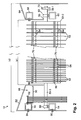
- Fig. 2 shows the disc screen 12 in a schematic side view.
- a conventional disk screen like a conventional disk screen (see, for example, the already mentioned at the outset DE 44 30 682 A1 ) comprises the Scheibensieb 12 a Scheibensiebsweeping 14 to Scheibensiebende 16 extending series of axially parallel waves, of which Fig. 2 one to recognize and designated 50.
- a plurality of spaced apart in the axial direction of disks 52 are arranged and rotatably connected to the respective associated shaft 50 during operation of the disk screen.
- the axial positions of the discs 52 are provided offset from shaft to shaft in such a way that the discs of comb-like mesh of adjacent waves.
- the discs 52 have a non-circular outer periphery, which is formed in the illustrated embodiment of a circle with a plurality of equidistantly distributed in the circumferential direction, arranged approximately semicircular indentations. Deviating from this, other peripheral designs are conceivable (eg, as with a so-called "star screen").
- the illustrated screen 12 has a number of advantageous features, which are the above with respect to Fig. 1 already described green waste separation with respect to the separation accuracy or adaptability of the device 10 respectively significantly improve currently required separation properties. These features are described in more detail below.
- the disk screen 12 comprises a longitudinal frame with frame profile parts 54, 56, 58 and 60, which serve for the storage of the example shown in the example 16 waves 50 and side cover plates 62 and 64.
- bearing brackets 66 and 68 are respectively arranged for supporting each shaft 50 for laterally supporting outer shaft sections 50-3 and 50-1, respectively.
- the upper frame profile parts 56 and 58 in the figure serve to stiffen the construction and, in the example shown, also to fasten the longitudinally extending cover plates 62 and 64.
- the rotary drive of the shafts 50 takes place by way of a drive gear wheel 70 which is connected in a rotationally fixed manner to the respective shaft section 50-1 and which during operation of the device 10 is driven by a drive chain (not shown) for rotating the respective shaft 50.
- the drive chain extends in this case in the longitudinal direction of the Scheibensiebrahmens within the area bounded by the cover plate 64 and is for simultaneous and co-rotational drive of all shafts 50 in engagement with all drive gears 70 of the shafts 50th
- each shaft 50 could also be provided for each shaft 50 own drive, for example, in each case an electric motor or a hydraulic motor.
- shaft section 50-2 In an axially central region of the shaft 50 (shaft section 50-2), this is designed as a hollow-cylindrical tube section which is closed on both sides and has a substantially larger diameter compared to the lateral shaft sections 50-1, 50-3.
- This axial region of the disk screen 12 is also referred to below as the "screen area” because only in this area does the screening (and the transport) of the applied material take place.
- the cover plates 62 and 64 cover the areas arranged on both sides thereof in order to prevent penetration of the material 30 applied from above onto the screen area into these areas.
- the size of the "screen openings" and thus the screen characteristic of the screen screen 12 is determined by the arrangement, shape and dimensions of the gaps, which remain between the shafts 50 and the discs 52 attached thereto.
- An advantageous feature of the disc screen 12 is that the number and axial arrangement of the discs 52 on each associated shaft 50 can be changed in a simple manner, such as to adapt the separator 10 to a new good to be separated.
- Fig. 2 left portion of the screen area exemplified with a relatively large density of discs 52
- the right part of the screen area is shown with a lower occupation density of discs 52.
- the discs 52 arranged distributed in the axial direction equidistantly, which is preferred in most applications.
- each disc 52 and the associated shaft 50 is provided, which in a first relative rotational position of the disc 52 with respect to the shaft 50 allows axial displacement of the disc 52 on the shaft 50 and in a second relative rotational position of the disc 52 with respect to the shaft 50 blocks such axial displacement.
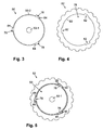
- Fig. 3 shows the shaft 50 viewed from the side.
- the shaft 50 has at three offset by 120 ° to each other arranged points of its circumference each radially outwardly projecting and in the axial direction over the entire screen area 50-. 2 extending locking bar 76th
- Fig. 4 shows in isolation the disc 52, which has a to the circumference of the shaft portion 50-2 of the shaft 50 for passage of the shaft 50 adapted passage opening 78, the opening edge 80 has three radially outwardly directed indentations 82.
- the indentations 82 like the arresting strips 76, are each offset by 120 ° relative to one another in order to allow the passage of the (correspondingly arranged) arresting strips 76 and thus an axial displacement of the disk 52 on the shaft 50.
- Each locking strip 76 has, on one of its sides viewed in the circumferential direction, a plurality of detent bays 84 spaced equidistant from each other in the axial direction.
- the Arretianssang 76 with the grid-like distributed in the axial direction arrangement of Arret michsbuchten 84 is also good in Fig. 2 recognizable.
- each detent bay 84 corresponds to the thickness of the disc 52 (plus, if appropriate, a certain amount of oversize which facilitates the screwing-in of the disc portion into the desired detent bay 84.
- Fig. 5 illustrates this situation in which the disc 52 is blocked on the shaft 50.
- the locking bar 76 apart from the Arretismesbuchten 84, designed as an axially extending profile with a square profile cross-section. Deviating from this, a different profile cross-section could also be provided. It is essential that the contour defined by the indentation edge of the disc 52 corresponds with the profile cross section of the locking strip 76 in such a way that the disc 52 can be slipped onto the shaft 50 or displaced on the shaft 50.
- the radially outer Profile cross-section edge of the locking strip 76 is not straight tangential or circular arc in the circumferential direction extending, but somewhat conical as shown (with a slight inclination or slope to the tangential or circumferential direction, eg., From about 1 to 10 °).
- the radially outer recessed edge portion on the disc 52 is not formed parallel to the radially outer profile cross-section edge of the locking strip 76, but on the other hand again slightly inclined (eg, about 1 to 2 °). This has the advantage that in a relative rotation of the disc 52 to block their Axialverschiebles a clamping of the disc 52 takes place in the radial direction, which fixes the disc 52 to the shaft 50.
- a clamping in the axial direction may be provided by z.
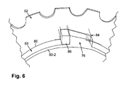
- Fig. 6 shows again in an enlarged perspective view of the area around a locking bar 76 with disc 52 blocked thereon.
- the disc screen 12 are in the screening area of the shaft 50 (shaft portion 52-2 in Fig. 2 ) z. B. a total of 40 Arret istsbuchten 84 provided on each locking bar 76 in the axial direction equidistantly distributed. Accordingly, when each of these detent bays 84 is occupied by a washer 52, there is a maximum of 40 washers 52 per shaft 50. This occupancy density is in Fig. 2 illustrated in the left part of the screen area. With an axial width b1 of the screen area of, for example, 1.5 m, this means that the disks 52 are arranged at a mutual distance of about 4 cm.
- a further advantageous feature of the disk screen 12 is that in a region surrounding the shaft section 50-3 (and covered by the cover plate 62 during operation of the device), a receiving space 88 is provided for accommodating the number of disks not required for the current operation of the device 10 52 is formed.
- the not required in the example described here 20 discs 52 find in this receiving space 88 place and as shown simply on a horizontal Bracket 90 lined up and optionally fixed by a screw 92.
- the headband 90 is formed in the example shown as a suitably shaped sheet and z. B. welded to the frame profile part 56.
- the cover plate 62 After stowing the currently not required discs 52 in the receiving space 88, the cover plate 62 is finally put back and fixed (screws 94 and 96).
- the disk screen 12 and the device 10 is ready for use with a newly set opening width of the disk screen 12th
- the inclination of the pulley 12 can be changed during the stoppage.
- the larger the skew angle with respect to the horizontal the more of the material applied by the conveyor belt 18 migrates to the material fraction 42 provided at the lower pulley screen start 14 (at the expense of the amount of fraction 38 provided at the upper pulp screen end 16).
- the skew angle has a meaning insofar as the material transport (transport direction T) is slower at a larger angle, which advantageously increases the selectivity between the oversize fraction 38 and the sieve fraction 34.
- an in Fig. 2 drawn width b2 of the Scheibensiebes 12 smaller than 3 m, preferably at most 2.5 m.
- Fig. 7 shows a further embodiment of a separating device 10a, the structure and function substantially the same with reference to FIG Fig. 1 corresponds to described embodiment.
- a modification of the illustrated device 10a with respect to the above-described device 10 is that to be separated green material 30a is not supplied by means of a transverse to Scheibensieb 12a conveyor belt but by means of a material feed hopper 18a, which has a parallel to the pulley 12a conveyor belt 19a.
- the conveyor belt 24 or 24a provided for conveying off the green material fraction 42 or 42a is not arranged as shown in a plane with the disk screen but extends transversely thereto (ie ab tot side).
- the supply of the material to be separated can also be carried out in a more expedient manner in the plane of the disk screen.
- it can be provided with a view to a possible universal usability of the separation device, that provided for the removal of the third material fraction discharge device, ie, for. B.
- the conveyor belt 24 and 24 a of the described embodiments is mounted so pivotable that the Ab raw politicians can be adapted to the respective requirements.
- the conveyor belt 24 or 24a could thus z. B. also sideways pivotable (from the drawing levels of Fig. 1 and 7 out) be provided. If in a specific application z. B. a supply of the material to be separated approximately parallel to the disc screen (see. Fig. 8 ), so this can be created more space by the discharge conveyor is pivoted at Scheibensiebsweeping accordingly (eg, to the left or right).
- Fig. 8 shows a still further embodiment of a separator 10b.
- the device 10b there are no discharge devices for removing the oversize fraction 42b arising at the beginning of the slice screen 14b and the oversize fraction 38b arising at the slice end 16b. These material fractions 42b, 38b simply fall on the floor next to the device 10b in this example.
- the material 30b to be separated is supplied by means of a conveying device (in this case for example so-called ascending conveyor) elongated in the plane of the disk screen 12b.
- a conveying device in this case for example so-called ascending conveyor
- pivotability which is also preferably provided in the case of the device 10b, or a pivoting region for the disk screen 12b, is in FIG Fig. 8 symbolized by a double arrow.
- a frame of the disk screen 12b is pivotably mounted about a pivot axis 98b in order to be able to adapt the disk screen progression with respect to the inclination to the respectively desired requirements.
- the pivot axis is realized by a corresponding pivot bearing on a support frame 100b, which consists essentially of two approximately U-shaped and arranged on both sides of the pulley screen 12b support frame brackets (In Fig. 8 one of these bars can be seen).
- the support frame 100b is not directly on the ground but is attached or attached via detachable fasteners 102b at upper edges of boundary walls 104b of a material bunker.
- this material bunker or the corresponding lateral boundary walls 104b may be z.
- B. may be a stationary device, whereas the other device components may also be designed for mobile use.
- the screen fraction 34b obtained below the screen screen 12b falls directly into an interior 106b of the material bunker.
- the concrete structural design of the support frame 100b can be modified in practice in many ways. A significant feature of the support frame 100b of the type shown is that so that a structurally simple Possibility of realizing a pivoting (see double arrow) of the Scheibensiebes 12b is created.
Landscapes
- Combined Means For Separation Of Solids (AREA)
- Processing Of Solid Wastes (AREA)
Applications Claiming Priority (1)
| Application Number | Priority Date | Filing Date | Title |
|---|---|---|---|
| DE200910014548 DE102009014548A1 (de) | 2009-03-24 | 2009-03-24 | Vorrichtung und Verfahren zum Trennen von Material, insbesondere Grüngut, sowie Verwendung hierfür |
Publications (2)
| Publication Number | Publication Date |
|---|---|
| EP2233217A2 true EP2233217A2 (fr) | 2010-09-29 |
| EP2233217A3 EP2233217A3 (fr) | 2010-10-06 |
Family
ID=42008510
Family Applications (1)
| Application Number | Title | Priority Date | Filing Date |
|---|---|---|---|
| EP20090011016 Withdrawn EP2233217A3 (fr) | 2009-03-24 | 2009-08-27 | Dispositif et procédé de séparation de matériau, notamment de fourrage vert, et utilisation correspondante |
Country Status (2)
| Country | Link |
|---|---|
| EP (1) | EP2233217A3 (fr) |
| DE (1) | DE102009014548A1 (fr) |
Cited By (4)
| Publication number | Priority date | Publication date | Assignee | Title |
|---|---|---|---|---|
| DE202012006328U1 (de) | 2012-06-29 | 2012-07-09 | Martin Hirschauer | Vorrichtung zur programmgesteuerten Fraktionierung vonRecycling-Material |
| DE102012012979A1 (de) | 2012-06-29 | 2014-01-02 | Martin Hirschauer | Verfahren und Vorrichtung zur programmgesteuertenFraktionierung von Recycling-Material |
| CN107350140A (zh) * | 2017-07-27 | 2017-11-17 | 临川环境技术(天津)有限公司 | 城市生活垃圾模块化碟盘筛分设备 |
| CN120169661A (zh) * | 2025-03-05 | 2025-06-20 | 庆云鲁庆制粉有限公司 | 面粉加工用谷物输送装置 |
Families Citing this family (1)
| Publication number | Priority date | Publication date | Assignee | Title |
|---|---|---|---|---|
| DE202017001636U1 (de) * | 2017-03-27 | 2017-07-10 | Veritec Ag | Vorrichtung zum Abtrennen von Fremdstoffen von einem Schüttgut |
Citations (1)
| Publication number | Priority date | Publication date | Assignee | Title |
|---|---|---|---|---|
| DE4430682A1 (de) | 1994-08-30 | 1996-03-07 | Ernst Josef Kronenberger | Scheibensieb |
Family Cites Families (3)
| Publication number | Priority date | Publication date | Assignee | Title |
|---|---|---|---|---|
| US3870627A (en) * | 1972-11-27 | 1975-03-11 | John W Herkes | Mechanical screening device for machine-harvested sugar cane |
| US7004332B2 (en) * | 2001-11-21 | 2006-02-28 | Cp Manufacturing, Inc. | Articulating disc screen apparatus for recyclable materials |
| US7584856B2 (en) * | 2006-11-03 | 2009-09-08 | Emerging Acquisitions, Llc | Air separation of recyclable material |
-
2009
- 2009-03-24 DE DE200910014548 patent/DE102009014548A1/de not_active Withdrawn
- 2009-08-27 EP EP20090011016 patent/EP2233217A3/fr not_active Withdrawn
Patent Citations (1)
| Publication number | Priority date | Publication date | Assignee | Title |
|---|---|---|---|---|
| DE4430682A1 (de) | 1994-08-30 | 1996-03-07 | Ernst Josef Kronenberger | Scheibensieb |
Cited By (5)
| Publication number | Priority date | Publication date | Assignee | Title |
|---|---|---|---|---|
| DE202012006328U1 (de) | 2012-06-29 | 2012-07-09 | Martin Hirschauer | Vorrichtung zur programmgesteuerten Fraktionierung vonRecycling-Material |
| DE102012012979A1 (de) | 2012-06-29 | 2014-01-02 | Martin Hirschauer | Verfahren und Vorrichtung zur programmgesteuertenFraktionierung von Recycling-Material |
| WO2014000728A1 (fr) | 2012-06-29 | 2014-01-03 | Martin Hirschauer | Procédé et dispositif de fractionnement de matériaux de recyclage commandé par ordinateur |
| CN107350140A (zh) * | 2017-07-27 | 2017-11-17 | 临川环境技术(天津)有限公司 | 城市生活垃圾模块化碟盘筛分设备 |
| CN120169661A (zh) * | 2025-03-05 | 2025-06-20 | 庆云鲁庆制粉有限公司 | 面粉加工用谷物输送装置 |
Also Published As
| Publication number | Publication date |
|---|---|
| DE102009014548A1 (de) | 2010-09-30 |
| EP2233217A3 (fr) | 2010-10-06 |
Similar Documents
| Publication | Publication Date | Title |
|---|---|---|
| EP2329891B1 (fr) | Dispositif et procédé de séparation de matériau, notamment de fourrage vert, et utilisation correspondante | |
| DE69608918T3 (de) | Zerkleinerungsvorrichtung | |
| WO2004112973A2 (fr) | Tamiseur a tambour | |
| EP1621522B1 (fr) | Dispositif pour mélanger des substances humides | |
| DE102012014085A1 (de) | Pflückeinheit, Erntevorsatz und Erntemaschine für Mais oder dergleichen | |
| EP0748583A1 (fr) | Moissonneuse-batteuse | |
| EP4308314B1 (fr) | Appareil de séparation de matériau d'alimentation | |
| DE2516111C2 (de) | Zerkleinerungsvorrichtung, insbesondere zur Verarbeitung von Papier und Kunststoffmaterial | |
| EP2058097A2 (fr) | Machine à déchiqueter | |
| AT509612B1 (de) | Vorrichtung zum verarbeiten von garten-, erdgut und dergleichen | |
| EP2300666B1 (fr) | Dispositif mobile muni d'un systeme d'enlevement | |
| DE68902795T2 (de) | Mischer, insbesondere fuer faserige produkte. | |
| DE3807983C2 (de) | Vorrichtung zum Zerkleinern | |
| EP2564694B1 (fr) | Dispositif d'acheminement | |
| WO2014000728A1 (fr) | Procédé et dispositif de fractionnement de matériaux de recyclage commandé par ordinateur | |
| EP0022537B1 (fr) | Machine pour le broyage d'objets encombrants | |
| DE102009014548A1 (de) | Vorrichtung und Verfahren zum Trennen von Material, insbesondere Grüngut, sowie Verwendung hierfür | |
| DE60105981T2 (de) | Vorrichtung zum zerschneiden von pflanzengut | |
| DE19603370C2 (de) | Erntemaschine | |
| DE102005030041A1 (de) | Siebvorrichtung für eine Siebmaschine | |
| DE2810359A1 (de) | Vorrichtung zum selektiven sortieren von materialschnitzeln | |
| EP2708340B1 (fr) | Dispositif de tri pour des copeaux de bois | |
| EP2140988A2 (fr) | Machine à découper des aliments et procédé de dépôt et de transport de tranches de produits à découper | |
| EP0801975A1 (fr) | Dispositif pour le traitement des déchets organiques | |
| DE10204772A1 (de) | Schneidwerk, insbesondere zur Zerkleinerung von Spänen |
Legal Events
| Date | Code | Title | Description |
|---|---|---|---|
| PUAI | Public reference made under article 153(3) epc to a published international application that has entered the european phase |
Free format text: ORIGINAL CODE: 0009012 |
|
| PUAL | Search report despatched |
Free format text: ORIGINAL CODE: 0009013 |
|
| AK | Designated contracting states |
Kind code of ref document: A2 Designated state(s): AT BE BG CH CY CZ DE DK EE ES FI FR GB GR HR HU IE IS IT LI LT LU LV MC MK MT NL NO PL PT RO SE SI SK SM TR |
|
| AX | Request for extension of the european patent |
Extension state: AL BA RS |
|
| AK | Designated contracting states |
Kind code of ref document: A3 Designated state(s): AT BE BG CH CY CZ DE DK EE ES FI FR GB GR HR HU IE IS IT LI LT LU LV MC MK MT NL NO PL PT RO SE SI SK SM TR |
|
| AX | Request for extension of the european patent |
Extension state: AL BA RS |
|
| 17P | Request for examination filed |
Effective date: 20110328 |
|
| 17Q | First examination report despatched |
Effective date: 20121022 |
|
| GRAP | Despatch of communication of intention to grant a patent |
Free format text: ORIGINAL CODE: EPIDOSNIGR1 |
|
| INTG | Intention to grant announced |
Effective date: 20150324 |
|
| STAA | Information on the status of an ep patent application or granted ep patent |
Free format text: STATUS: THE APPLICATION IS DEEMED TO BE WITHDRAWN |
|
| 18D | Application deemed to be withdrawn |
Effective date: 20150804 |