EP2233221A2 - Punching device for a progressive die punching machine for metal punched parts - Google Patents
Punching device for a progressive die punching machine for metal punched parts Download PDFInfo
- Publication number
- EP2233221A2 EP2233221A2 EP10405048A EP10405048A EP2233221A2 EP 2233221 A2 EP2233221 A2 EP 2233221A2 EP 10405048 A EP10405048 A EP 10405048A EP 10405048 A EP10405048 A EP 10405048A EP 2233221 A2 EP2233221 A2 EP 2233221A2
- Authority
- EP
- European Patent Office
- Prior art keywords
- punching
- station
- punching device
- follow
- punch press
- Prior art date
- Legal status (The legal status is an assumption and is not a legal conclusion. Google has not performed a legal analysis and makes no representation as to the accuracy of the status listed.)
- Withdrawn
Links
- 238000004080 punching Methods 0.000 title claims abstract description 65
- 239000002184 metal Substances 0.000 title claims abstract description 20
- 230000000750 progressive effect Effects 0.000 title description 3
- 210000000078 claw Anatomy 0.000 claims abstract description 7
- 238000005516 engineering process Methods 0.000 claims description 7
- 238000004519 manufacturing process Methods 0.000 claims description 3
- 238000005520 cutting process Methods 0.000 abstract description 4
- 238000007599 discharging Methods 0.000 abstract 1
- 238000000034 method Methods 0.000 description 5
- 230000007246 mechanism Effects 0.000 description 2
- 238000000926 separation method Methods 0.000 description 2
- 241001136792 Alle Species 0.000 description 1
- 238000006243 chemical reaction Methods 0.000 description 1
- 210000002023 somite Anatomy 0.000 description 1
- 238000003856 thermoforming Methods 0.000 description 1
Images
Classifications
-
- B—PERFORMING OPERATIONS; TRANSPORTING
- B21—MECHANICAL METAL-WORKING WITHOUT ESSENTIALLY REMOVING MATERIAL; PUNCHING METAL
- B21D—WORKING OR PROCESSING OF SHEET METAL OR METAL TUBES, RODS OR PROFILES WITHOUT ESSENTIALLY REMOVING MATERIAL; PUNCHING METAL
- B21D28/00—Shaping by press-cutting; Perforating
- B21D28/24—Perforating, i.e. punching holes
- B21D28/36—Perforating, i.e. punching holes using rotatable work or tool holders
-
- B—PERFORMING OPERATIONS; TRANSPORTING
- B21—MECHANICAL METAL-WORKING WITHOUT ESSENTIALLY REMOVING MATERIAL; PUNCHING METAL
- B21D—WORKING OR PROCESSING OF SHEET METAL OR METAL TUBES, RODS OR PROFILES WITHOUT ESSENTIALLY REMOVING MATERIAL; PUNCHING METAL
- B21D24/00—Special deep-drawing arrangements in, or in connection with, presses
- B21D24/005—Multi-stage presses
-
- B—PERFORMING OPERATIONS; TRANSPORTING
- B21—MECHANICAL METAL-WORKING WITHOUT ESSENTIALLY REMOVING MATERIAL; PUNCHING METAL
- B21D—WORKING OR PROCESSING OF SHEET METAL OR METAL TUBES, RODS OR PROFILES WITHOUT ESSENTIALLY REMOVING MATERIAL; PUNCHING METAL
- B21D28/00—Shaping by press-cutting; Perforating
- B21D28/24—Perforating, i.e. punching holes
- B21D28/26—Perforating, i.e. punching holes in sheets or flat parts
-
- B—PERFORMING OPERATIONS; TRANSPORTING
- B21—MECHANICAL METAL-WORKING WITHOUT ESSENTIALLY REMOVING MATERIAL; PUNCHING METAL
- B21D—WORKING OR PROCESSING OF SHEET METAL OR METAL TUBES, RODS OR PROFILES WITHOUT ESSENTIALLY REMOVING MATERIAL; PUNCHING METAL
- B21D37/00—Tools as parts of machines covered by this subclass
- B21D37/08—Dies with different parts for several steps in a process
-
- B—PERFORMING OPERATIONS; TRANSPORTING
- B21—MECHANICAL METAL-WORKING WITHOUT ESSENTIALLY REMOVING MATERIAL; PUNCHING METAL
- B21D—WORKING OR PROCESSING OF SHEET METAL OR METAL TUBES, RODS OR PROFILES WITHOUT ESSENTIALLY REMOVING MATERIAL; PUNCHING METAL
- B21D43/00—Feeding, positioning or storing devices combined with, or arranged in, or specially adapted for use in connection with, apparatus for working or processing sheet metal, metal tubes or metal profiles; Associations therewith of cutting devices
- B21D43/02—Advancing work in relation to the stroke of the die or tool
- B21D43/04—Advancing work in relation to the stroke of the die or tool by means in mechanical engagement with the work
- B21D43/05—Advancing work in relation to the stroke of the die or tool by means in mechanical engagement with the work specially adapted for multi-stage presses
-
- B—PERFORMING OPERATIONS; TRANSPORTING
- B21—MECHANICAL METAL-WORKING WITHOUT ESSENTIALLY REMOVING MATERIAL; PUNCHING METAL
- B21D—WORKING OR PROCESSING OF SHEET METAL OR METAL TUBES, RODS OR PROFILES WITHOUT ESSENTIALLY REMOVING MATERIAL; PUNCHING METAL
- B21D43/00—Feeding, positioning or storing devices combined with, or arranged in, or specially adapted for use in connection with, apparatus for working or processing sheet metal, metal tubes or metal profiles; Associations therewith of cutting devices
- B21D43/02—Advancing work in relation to the stroke of the die or tool
- B21D43/04—Advancing work in relation to the stroke of the die or tool by means in mechanical engagement with the work
- B21D43/14—Advancing work in relation to the stroke of the die or tool by means in mechanical engagement with the work by turning devices, e.g. turn-tables
Definitions
- the present invention relates to a punching device for a follow-cut punching machine for the production of metal stamped parts according to the preamble of patent claim 1.
- the metal part is processed in a series of workstations which are each provided with at least one punch and one die, each of which is provided for carrying out a specific work step, for example for severing and / or folding and / or drawing or thermoforming.
- a specific work step for example for severing and / or folding and / or drawing or thermoforming.
- the metal part changes shape until the final shape is achieved according to the design drawing.
- stamp here always a combination of one or more stamps in conjunction with its own associated die to understand.
- a "simple" punch press that can perform a single punching operation has a punch and a single die, while a progressive punch press has a series of punches, each with its own die.
- the feed of the sheet metal strip, and thus also of the stamped part is given by the feed device of the punch press, which advances the strip by one "step" for each punching stroke (the step being in the case of a number of more than two workstations of the follow-cut punch press is equal to the distance between one workstation and the next one).
- the above-described technology of the following step punching can not be used, in which the stamped part remains connected to the sheet metal strip and thus transported with it until it is cut off (cut off) only at the last work station. It may happen, for example, that certain stampings have no area in which the connection with the sheet-metal strip can remain. In such cases, the stamped part must already be separated from the band at the first workstation and then brought as a separate or independent part to the subsequent workstations.
- transfer punching technology in which the punching device is replaced by a series of individual stations arranged in a straight line, the transfer from one station to the next by means of a series of grippers accomplished, which are attached to a transporting arm.
- transfer punch press Such a transport system becomes an integral part of the stamping press, thus called “transfer punch press”, which is a special punch press type.
- this particular type of punch press is known as a "transfer punch press", with punching stations arranged in a single plane for punched parts cut off from the sheet metal strip from the first work station.
- This is, in the sense of an example, from the EP0778094 can be seen in the gripper devices formed by gripper tongs, with an access station and with an unloading station, wherein each of the clamping devices is mounted on a suitable sliding rod, or from the DE4022560 in which the punching stations are arranged along a zig-zag course to reduce the space requirement, the gripper arms transporting the stamped parts along this path.
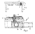
- the Fig. 1 shows the punching press according to the invention in elevation. It consists of an upper part 1 and a lower part. 2
- Fig. 1 In the Fig. 1 are the two parts 1 and 2, which together form the punching device, are shown lifted off from each other: this is the position of the punching device in its open position or rest position. It is clear that in the working position, the punching stroke, the upper part 1 lowers to the lower part 2, so that the stamp (in the Fig. 2 only one punch 3 is shown in section) can penetrate into the corresponding dies 4, which in the Fig. 2 can be seen better, showing the bottom of the punching press in plan.
- the punching device 1,2 is shown on a punch press, which is not shown here for the sake of clarity, and because it is a conventional punch press type comprising a base 2 supporting frame, a horizontal portal on which the upper part. 1 the punching device is attached, as well as vertical guides along which the portal can move upwards (for opening the punching device) and downwards (for closing the punching device during the punching stroke), and the required movement and control mechanisms for the portal. All these movements are in the Fig. 1 indicated by the double arrow f itself, which indicates the movements of the upper part of the punching device upwards and downwards.
- the upper part 1 of the punching device consists of a substantially horizontal plate 5, on which the punch 3 in a well-defined arrangement resulting from the positions of the dies 4, which are fixed in the lower part 2 of the punching device, and, as explained later is a basic aspect of the present invention, as well as four guide elements 6 (one for each corner of the plate 5) whose purpose it is to guide the plate exactly when lowering on the lower part 2 of the punching device.
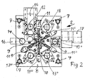
- Fig. 2 showing the bottom part 2 of the punching device with the top removed in plan view.
- Fig. 2 corresponds to the horizontal plate 8 of the lower part 2 of the punching device in shape of the plate 5 in the upper part 1, wherein through the center of the axis of rotation 9 of an arm star 10 extends, which is provided with gripper claws 11.
- the processing stations 12, 13, 13 ', 13 ", 13"' have matrices 4, each of which is designed for the operation to be performed in cooperation with the corresponding punch 3.
- Each processing station is thus equipped with a punch and a die which are different from those of the preceding station, so that the continuous deformation of the stamped part is performed.
- the processing stations 12, 13, 13 ', 13 ", 13"' and 14 are arranged according to the invention along a circular path which begins with a loading and cutting station 12 and ends with an unloading station 14.
- the charging station 12 while the stamped part is separated or cut from the metal strip 15 and thus becomes an independent part, which at best also experiences a first deformation by pulling during the separation, and thus, after it has been gripped by the gripper jaw 11 of the corresponding arm of the arm star 10, can be transported to the next processing station 13 , To perform this operation, the arm star 10, starting from his in the Fig.
- the arm star 10 shown at first a rotational movement about the center of the circular path from, in the counterclockwise direction, over an angle corresponding to half the angular distance between two successive arms of the arm star 10, so that the gripper claw 11 over the separated in the processing station 12 part located. Then, the claw 11 suitably grips the part and the arm of the star-shaped arm 10 rotates clockwise through an angle corresponding to the angular distance between two consecutive arms of the arm star 10, so that the part is in coaxial coincidence with the processing station 13 is brought. Then, the arm star 10 returns to its original position by making a counterclockwise rotation through an angle equal to half the angular distance between two successive arms of the arm star 10.
- the number of arms of Arm Star 10 depends on the number of processing stations provided along the circular path, and is always equal to this number minus one.
- FIGS. 1 and 2 In the illustrated case of an implementation of the present invention, which may be considered as a preferred case for many practical applications, six processing stations 12, 13, 13 ', 13 ", 13"' and 14 are provided which are angularly spaced from one another by 60 ° station arranged to the other.
- the arm star 10 has five arms, between two of which - those cooperating with the loading and unloading station 12 and the unloading station 14 - the angular distance is 120 °.
- FIGS. 1 and 2 is, merely in the sense of an example, a drive motor 17 for the arm star 10 shown, which acts via a reduction gear 18 and a camshaft 19.
- this arrangement is not part of the inventive idea and is left to the creativity of the designer.
- the present invention has been described here on the basis of a vertical punch press, in which the upper part 1 of the punching device is lowered onto the lower part 2 in a vertical movement.
- This is a preferred way of realizing the inventive concept, as it allows the use of normal punching presses with vertical lifting movement.
- the present invention can also be applied independently of the particular arrangement of the plane in which the circular path of the processing stations is designed, for example on stamping presses in which the lifting movement of the punching in the horizontal or similar (inclined) direction he follows.
- the access type of gripper jaws 11, 11 ', 11 ", 11"', 11 IV of the arm star 10 on the stamped part depending on the shape of the can be different to be produced stamped part.
- the gripper jaws 11,... 11 IV are equipped with pliers which mechanically grasp the stamped part, wherein according to a further preferred embodiment of the present invention, the pliers are pneumatic or hydraulically operated.
- a further preferred embodiment of the present invention then provides that the gripper jaws 11, 11 ', 11 ", 11"', 11 IV are equipped for the metallic stampings with suction cups, which access by means of pneumatic suction, or by means of magnetic attraction.
Landscapes
- Engineering & Computer Science (AREA)
- Mechanical Engineering (AREA)
- Press Drives And Press Lines (AREA)
Abstract
Description
Die vorliegende Erfindung betrifft eine Stanzvorrichtung für eine Folgeschnitt-Stanzmaschine zum Herstellung von Metall-Stanzteilen gemäss dem Oberbegriff des Patentanspruchs 1.The present invention relates to a punching device for a follow-cut punching machine for the production of metal stamped parts according to the preamble of patent claim 1.
Beim Folgeschnittstanzen von Metall-Stanzteilen wird das Metallteil in einer Reihe von Arbeitsstationen bearbeitet, die mit je mindestens einem Stempel und einer Matrize versehen sind, von denen jede zur Ausführung eines bestimmten Arbeitsschrittes vorgesehen ist, beispielsweise zum Abtrennen und/oder Abkanten und/oder Ziehen bzw. Tiefziehen. Beim Durchlaufen der Arbeitsstationen ändert das Metallteil seine Form, bis die endgültige Form entsprechend der Konstruktionszeichnung erreicht ist.In the case of punching metal stamped parts, the metal part is processed in a series of workstations which are each provided with at least one punch and one die, each of which is provided for carrying out a specific work step, for example for severing and / or folding and / or drawing or thermoforming. As the workstations pass through, the metal part changes shape until the final shape is achieved according to the design drawing.
Gemäss der bekannten Technik des Folgeschnittstanzens ist die Übergabe bzw. Transfer der Teile von einer Arbeitsstation an die folgende dadurch gewährleistet, dass das Stanzteil mit dem Blechband verbunden bleibt, von welchem es erst an der letzten Arbeitsstation weggenommen wird. Festgehalten sei hier, dass der Begriff "Stempel" hier immer eine Kombination eines oder mehrerer Stempel in Verbindung mit der eigenen zugehörigen Matrize zu verstehen ist.According to the known technique of follow-cut punching, the transfer or transfer of the parts from one workstation to the next is ensured by the fact that the stamped part remains connected to the sheet-metal strip, from which it is only removed at the last workstation. It should be noted here that the term "stamp" here always a combination of one or more stamps in conjunction with its own associated die to understand.
Eine "einfache" Stanzpresse, die eine einzige Stanzoperation ausführen kann, besitzt also einen Stempel und eine einzige Matrize, während eine Folgeschnitt-Stanzmaschine eine Reihe von Stempeln aufweist, von denen jeder mit seiner eigenen Matrize versehen ist.Thus, a "simple" punch press that can perform a single punching operation has a punch and a single die, while a progressive punch press has a series of punches, each with its own die.
In der bisher bekannten Folgeschnitt-Stanztechnik ist der Vorschub des Blechbandes, und damit auch des Stanzteils, durch die Vorschubeinrichtung der Stanzpresse gegeben, die das Band für jeden Stanzhub um einen "Schritt" vorschiebt (wobei der Schritt im Fall von einer Anzahl von mehr als zwei Arbeitsstationen der Folgeschnitt-Stanzpresse gleich dem Abstand zwischen einer Arbeitsstation und der darauffolgenden ist).In the previously known follow-cut punching technique, the feed of the sheet metal strip, and thus also of the stamped part, is given by the feed device of the punch press, which advances the strip by one "step" for each punching stroke (the step being in the case of a number of more than two workstations of the follow-cut punch press is equal to the distance between one workstation and the next one).
In gewissen Fällen kann wegen der Ausgestaltung des Stanzteils die oben beschriebene Technologie des Folgeschrittstanzens nicht angewendet werden, bei welcher das Stanzteil mit dem Blechband verbunden bleibt und somit mit diesem transportiert wird, bis es erst bei der letzten Arbeitsstation davon getrennt (abgeschnitten) wird. Es kann beispielsweise vorkommen, dass gewisse Stanzteile keinen Bereich aufweisen, in welchem die Verbindung mit dem Blechband bestehen bleiben kann. In solchen Fällen muss das Stanzteil bereits bei der ersten Arbeitsstation vom Band getrennt werden und dann als abgetrenntes oder unabhängiges Teil zu den nachfolgenden Arbeitsstationen gebracht werden.In certain cases, because of the configuration of the stamped part, the above-described technology of the following step punching can not be used, in which the stamped part remains connected to the sheet metal strip and thus transported with it until it is cut off (cut off) only at the last work station. It may happen, for example, that certain stampings have no area in which the connection with the sheet-metal strip can remain. In such cases, the stamped part must already be separated from the band at the first workstation and then brought as a separate or independent part to the subsequent workstations.
Gemäss dem Stand der Technik wird in solchen Fällen die so genannte "Transfer-Stanztechnologie" angewendet, bei welcher die Stanzeinrichtung durch eine Reihe einzelner, auf einer geraden Linie angeordneter Stationen ersetzt wird, wobei die Weitergabe von einer Station zur darauffolgenden mittels einer Reihe von Greifern bewerkstelligt wird, die an einem transportierenden Arm befestigt sind. Ein solches Transportsystem wird zum integrierenden Bestandteil der Stanzpresse, die solchermassen ausgerüstet als "Transfer-Stanzpresse" bezeichnet wird, und die einen besonderen Stanzpressen-Typ darstellt.According to the prior art, in such cases the so-called "transfer punching technology" is used in which the punching device is replaced by a series of individual stations arranged in a straight line, the transfer from one station to the next by means of a series of grippers accomplished, which are attached to a transporting arm. Such a transport system becomes an integral part of the stamping press, thus called "transfer punch press", which is a special punch press type.
In der Patentliteratur ist dieser besondere Stanzpressen-Typ als "Transfer-Stanzpresse" bekannt, mit in einer Ebene angeordneten Stanz-Stationen für ausgestanzte und von der ersten Arbeitsstation an vom Blechband abgetrennte Stanzteile. Dies ist, im Sinne eines Beispiels, aus der
Aus der Praxis sind viele Anwendungen dieses Transfer-Systems bekannt, bei denen die Stanzteile längs eines mehr oder weniger gradlinigen Kurses weitergereicht werden, wobei sich die Nachteile dieses Systems folgendermassen zusammengefasst werden können:
- a) Notwendigkeit, Stanzpressen vorzusehen, die speziell für diese Art der Weitergabe der Stanzteile ausgerüstet sind, wodurch sie sich von den einfachen Folgeschnitt-Stanzpressen unterscheiden, die ohne besondere Vorrichtungen für den Transport der Stanzteile auskommen, weil die Stanzpresse mit einem einfachen Vorschubmechanismus ausgerüstet ist, der den Blechstreifen schrittweise vorschiebt;
- b) Beträchtlicher Platzbedarf, weil die verschiedenen, in einer Ebene angeordneten Stanz-Stationen beachtlichen Raum benötigen.
- a) Need to provide stamping presses that are specially equipped for this type of transfer of the stamped parts, which distinguishes them from the simple follow-cut stamping presses, which do without special devices for the transport of stampings, because the punch press is equipped with a simple feed mechanism who advances the sheet metal strip step by step;
- b) Considerable space, because the different, arranged in a plane punching stations require considerable space.
Die vorliegende Erfindung schlägt daher vor, die gemäss der beschriebenen und bekannten Transfer-Stanztechnologie längs eines gradlinigen Pfades noch vorhandenen Nachteile zu beheben, und gegenüber dem Stand der Technik insbesondere die folgenden Vorteile zu erreichen:
- 1. Möglichkeit, eine gewöhnliche Folgeschritt-Stanzpresse ohne ein längs eines linear ausgelegten Pfades Transfer-System zu verwenden, womit die Notwendigkeit entfällt, verschieden ausgerüstete Maschinen (Transfer-Stanzen oder Folgeschnitt-Stanzen) haben zu müssen. Alle Maschinen, über die der Stanz-Betrieb verfügt, können somit gleich ausgerüstet sein, was bessere Auswechselbarkeit und bessere Anpassungsfähigkeit des Betriebs sicherstellt;
- 2. Verkleinern des Platzbedarfs im Vergleich mit einem Transfer-Stanzsystem mit gradlinig aufgereihten Stanz-Stationen. Geringerer Platzbedarf bedeutet kleinere Kosten;
- 3. Dank der Kompaktheit der Stanzpresse können kleinere bzw. mit weniger Stanzkräften und damit geringerem Energieverbrauch arbeitende Stanzpressen verwendet werden;
- 4. Reduktion der Stillstandszeiten für das Umrüsten der Stanzpresse für zu produzierende Stanzteile (auch Einrichtzeiten genannt) gegenüber einer linear ausgelegten Transfer-Stanzpresse. Diese Reduktion kann, wie die Praxis gezeigt hat, bis zu etwa 50% betragen.
- 1. Possibility of using an ordinary sequential punch press without a linear path transfer system, eliminating the need to have differently equipped machines (transfer punching or progressive punching). All machines that have the punching operation can thus be equipped the same, which ensures better interchangeability and better adaptability of the operation;
- 2. Reduction of the space requirement in comparison with a transfer punching system with straight-lined punching stations. Less space required means lower costs;
- 3. Thanks to the compactness of the punch press, smaller or less punching and thus less energy consuming punch presses can be used;
- 4. Reduction of downtimes for the conversion of the punch press for punched parts to be produced (also called set-up times) compared to a linear transfer punch press. This reduction can, as the practice has shown, be up to about 50%.
Dies alles ergibt eine bessere Rentabilität der Stanz-Anlage.All this gives a better profitability of the punching plant.
Diese Vorteile werden erreicht mit einer Stanzvorrichtung für eine Folgeschnitt-Stanzpresse für Metall-Stanzteile gemäss dem Oberbegriff des Anspruchs 1, die die besonderen Merkmale entsprechend dem kennzeichnenden Teil des Anspruchs 1 aufweist.These advantages are achieved with a punching device for a subsequent punching press for metal stampings according to the preamble of claim 1, which has the special features according to the characterizing part of claim 1.
Neu und erfinderisch ist, über die Anwendung der genannten Transfer-Stanztechnologie hinaus, auf einer dafür nicht besonders eingerichteten Stanzpresse (also ohne die bekannten Transfer-Systeme längs einem linearen Pfad) die Eigenschaft, dass die Abschneidestation und die Stanz-Stationen längs einem kreisförmigen Pfad angeordnet sind, der mit einer Einzugs- und Abtrennstation beginnt und mit einer Entladestation für das fertige Stanzteil endet.What is new and inventive, beyond the application of said transfer punching technology, on a stamping press not particularly equipped for this purpose (ie without the known transfer systems along a linear path) is the property that the cutting station and the stamping stations are along a circular path are arranged, which starts with a collection and separation station and ends with an unloading station for the finished stamped part.
Dank dieser Eigenschaft der erfindungsgemässen Stanzpresse kann eine gewöhnliche Folgeschnitt-Stanzpresse ohne lineare Transportsysteme verwendet werden, mit allen erwähnten praktischen Vorteilen, insbesondere bezüglich Kosten.Thanks to this feature of the punch press according to the invention, an ordinary follow-up punch press without linear transport systems can be used, with all the mentioned practical advantages, in particular with regard to costs.
Die vorliegende Erfindung wird im Folgenden anhand eines Realisierungs-Beispiels beschrieben, unter Bezugnahme auf die entsprechenden Abbildungen. Diese Zeigen in der:
- Fig. 1
- Die Stanzvorrichtung der erfindungsgemässen Stanzpresse teilweise schematisch im Aufriss dargestellt;
- Fig. 2
- Grundriss der erfindungsgemässen Stanzpresse, bei abgenommenem Oberteil der Stanzpresse von oben gesehen;
- Fig. 1
- The punching device of the punching press according to the invention is shown partially schematically in elevation;
- Fig. 2
- Floor plan of the punching press according to the invention, seen from above when the upper part of the punching press is removed;
Die
In der
Selbstverständlich ist die Stanzvorrichtung 1,2 auf einer Stanzpresse gezeigt, die hier besserer Klarheit halber selbst nicht dargestellt ist, und weil es sich um einen konventionellen Stanzpressentyp handelt, der ein den Unterteil 2 tragendes Gestell, ein horizontales Portal umfasst, an welchem der Oberteil 1 der Stanzvorrichtung befestigt ist, sowie vertikale Führungen, längs welchen sich das Portal nach oben (zum Öffnen der Stanzvorrichtung) und nach unten (zum Schliessen der Stanzvorrichtung beim Stanzhub) bewegen kann, und die erforderlichen Bewegungs- und Steuerungsmechanismen für das Portal. Alle diese Bewegungen sind in der
Der Oberteil 1 der erfindungsgemässen Stanzvorrichtung besteht aus einer im wesentlichen horizontalen Platte 5, an welcher die Stempel 3 in genau definierter Anordnung, die sich aus den Stellungen der Matrizen 4 ergibt, die im Unterteil 2 der Stanzvorrichtung befestigt sind, und die, wie später erklärt wird, einen grundlegenden Aspekt der vorliegenden Erfindung darstellt, sowie aus vier Führungselementen 6 (eines für jede Ecke der Platte 5), deren Zweck darin besteht, die Platte beim Absenken auf den Unterteil 2 der Stanzvorrichtung genau zu führen. Diese Führungselemente 6, auch Säulen genannt, dringen dabei in die Büchsen 7 (ebenfalls vier und rohrförmig) ein und führen den Oberteil 1 sehr genau vertikal gegenüber dem Unterteil 2.The upper part 1 of the punching device according to the invention consists of a substantially
Zu unterstreichen ist dabei, dass bei offener Stanzvorrichtung 1, 2 die Säulen 6 nicht unbedingt aus den Büchsen 7 austreten, wie dies in der
Zum Verständnis der vorliegenden Erfindung ist die
In der
Auf der Platte 8 sind sodann befestigt:
- eine Speise- und Abschneide-
Station 12 für den Metallstreifen; - vier Stanz-
oder Ziehstationen eine Entladestation 14 für das fertige Stanzteil.
- a feeding and cutting
station 12 for the metal strip; - four punching or drawing
stations - an unloading
station 14 for the finished stamped part.
Die Bearbeitungsstationen 12, 13, 13', 13", 13"' weisen Matrizen 4 auf, von denen jede für den im Zusammenwirken mit dem entsprechenden Stempel 3 auszuführenden Arbeitsschritt ausgelegt ist. Jede Bearbeitungsstation ist also mit einem Stempel und einer Matrize ausgerüstet, die von jenen der vorangehenden Station verschieden sind, damit die fortlaufende Verformung des Stanzteils durchgeführt wird.The
Die Bearbeitungsstationen 12, 13, 13', 13", 13"' und 14 sind erfindungsgemäss längs eines kreissförmigen Pfades angeordnet, der mit einer Lade- und Abschneidestation 12 beginnt und mit einer Entladestation 14 endet. In der Ladestation 12 wird dabei das Stanzteil vom Blechstreifen 15 abgetrennt bzw. abgeschnitten und wird so zu einem unabhängigen Teil, das allenfalls während des Abtrennens auch eine erste Verformung durch Ziehen erfährt, und das somit, nachdem es von der Greiferklaue 11 des entsprechenden Armes des Arm-Sterns 10 gefasst worden ist, zur nächsten Bearbeitungsstation 13 transportiert werden kann. Zum Ausführen dieser Operation führt der Arm-Stern 10 ausgehend von seiner in der
Dieser Ablauf wiederholt sich sooft als erforderlich, um das fertige Teil zur Entladestation 14 zu bringen, wo das Teil aus der Klaue 11IV des entsprechenden Arms des Arm-Sterns 10 befreit und auf einer Rutsche 16 wegtransportiert wird.This process repeats as often as necessary to bring the finished part to the unloading
Die Anzahl Arme des Arm-Sterns 10 (in der
In dem in den
Die Anzahl der Arbeitsstationen, und damit die entsprechende Auslegung des Arm-Sterns 10, kann selbstverständlich innerhalb recht weiten Grenzen variieren, die hauptsächlich durch die Abmessungen der Trägerplatten 5 und 8 und die Abmessungen der zu produzierenden Teile diktiert werden, immer im Rahmen der vorliegenden Erfindung.The number of work stations, and thus the corresponding design of the
Die beschriebene abwechselnde Drehbewegung des Arm-Sterns 10 (eine Art Pilgerschritt-Bewegung) kann auf verschiedene Arten verwirklicht werden, von denen die klassische Lösung mittels eines passend gesteuerten Schrittmotors bewerkstelligt wird, eine Technik, die jedem Fachmann auf dem Gebiet vertraut ist.The described alternating rotational movement of the arm star 10 (a type of pilgrim step movement) can be accomplished in various ways, the classical solution of which is accomplished by means of an appropriately controlled stepping motor, a technique familiar to any person skilled in the art.
In den
Die vorliegende Erfindung wurde hier auf der Basis einer vertikal arbeitenden Stanzpresse beschrieben, bei welcher der Oberteil 1 der Stanzvorrichtung in vertikaler Bewegung auf den Unterteil 2 abgesenkt wird. Dies ist eine bevorzugte Art der Realisierung des erfindungsgemässen Konzepts, da sie die Verwendung normaler Stanzpressen mit vertikaler Hubbewegung erlaubt. Zu unterstreichen ist hier jedoch, dass die vorliegende Erfindung auch unabhängig von der besonderen Anordnung der Ebene, in welcher der kreisförmige Pfad der Bearbeitungsstationen ausgelegt ist, angewendet werden kann, beispielsweise auf Stanzpressen bei welchen die Hubbewegung des Stanzens in horizontaler oder ähnlicher (geneigter) Richtung erfolgt.The present invention has been described here on the basis of a vertical punch press, in which the upper part 1 of the punching device is lowered onto the
Schon vorgängig wurde festgehalten, dass die Zugriff-Art der Greiferklauen 11, 11', 11 ", 11 "', 11IV des Arm-Sterns 10 auf das Stanzteil je nach der Form des zu produzierenden Stanzteils verschieden sein kann. So sind beispielsweise gemäss einer bevorzugten Ausführungsform der vorliegenden Erfindung (nicht in den Figuren dargestellt) die Greiferklauen 11, .... 11IV mit Zangen ausgerüstet, welche as Stanzteil mechanisch erfassen, wobei gemäss einer weiteren bevorzugten Ausführungsform der vorliegenden Erfindung die Zangen pneumatisch oder hydraulisch betätigt werden können.Earlier it was noted that the access type of
Eine weitere bevorzugte Ausführungsform der vorliegenden Erfindung sieht sodann vor, dass die Greiferklauen 11, 11', 11 ", 11 "', 11IV für die metallischen Stanzteile mit Saugnäpfen ausgerüstet sind, die mittels pneumatischem Ansaugen zugreifen, oder mittels magnetischer Anziehungskraft.A further preferred embodiment of the present invention then provides that the
Alle diese speziellen Ausführungsformen der Greiferklauen 11, 11', 11 ", 11"', 11IV sowie weitere vorstellbare Lösungen stehen dem Fachmann auf dem Gebiet zur Verfügung, der sie entsprechend der vorgesehenen Verwendung der hier beschriebenen erfindungsgemässen Technologie auswählt.All of these specific embodiments of the
Die Vorteile der vorliegenden Erfindung wurden schon weiter oben als Zweck der Erfindung beschrieben, so dass sie hier keiner weiteren Erklärung bedürfen. Anpassungsfähigkeit des Arbeitsvorgangs, geringer Platzbedarf, geringerer Energiebedarf, kurze Stillstandszeiten zur Anpassung der konventionellen Stanzpresse, usw., sind alles Faktoren, die die Wirtschaftlichkeit der Produktion metallischer Stanzteile aus einem Blechband beeinflussen; Vorteile, die insbesondere dank der Anordnung erreicht werden, dass die Bearbeitungsstationen längs einem kreisförmigen Pfad angeordnet sind, anders als längs einem linearen Pfad gemäss dem bekannten Stand der Technik der Transfer-Stanztechnologie.The advantages of the present invention have already been described above as the purpose of the invention, so that they need not be further explained here. Adaptability of the work process, small footprint, lower energy requirements, short downtimes to adapt the conventional punch press, etc., are all factors that affect the economics of the production of metallic stampings from a sheet metal strip; Advantages achieved in particular by the arrangement that the processing stations are arranged along a circular path, unlike along a linear path according to the known state of the art of transfer punching technology.
- 11
- Oberteil der StanzpresseTop part of the punch press
- 22
- Unterteil der StanzpresseLower part of the punch press
- 33
- Stempelstamp
- 44
- Matrizedie
- 55
- Horizontale Platte des Oberteils 1Shell horizontal shell 1
- 66
- Führung oder SäuleLeadership or pillar
- 77
- BuchseRifle
- 88th
-
Horizontale Platte des Unterteils 2Bottom
horizontal panel 2 - 99
- Drehachseaxis of rotation
- 1010
- Arm-SternArm star
- 11, 11', 11 ", 11 "', 11IV 11, 11 ', 11 ", 11"', 11 IV
- Greiferklauegripper claw
- 1212
- Lade- und AbtrennstationLoading and separating station
- 13, 13', 13", 13"',13, 13 ', 13 ", 13"',
- Stanz- oder ZiehstationPunching or drawing station
- 1414
- Entladestationunloading
- 1515
- Blechstreifen (Band)Sheet metal strip (band)
- 1616
- Transportrutschetransport slide
- 1717
- Motorengine
- 1818
- UntersetzungsgetriebeReduction gear
- 1919
- Nockenwellecamshaft
Claims (7)
dadurch gekennzeichnet, dass
die Bearbeitungsstationen der Stanzpresse (12, 13, 13', 13", 13"', 14) längs einem kreisförmigen Pfad angeordnet sind, der mit einer Vorschub- und Abtrenn-Station (12) beginnt und mit einer Entladestation (14) endet, und dass
der Transfer des Stanzteils von einer Bearbeitungsstation zur nächstfolgenden mittels eines Arm-Sterns (10) bewerkstelligt wird, der um eine Achse rotiert, die durch das Zentrum des kreisförmigen Pfades geht und senkrecht zur Ebene steht, die durch die Matrizen (4) der Bearbeitungsstationen (12, 13, 13', 13", 13"', 14) der Stanzpresse definiert ist, und der mit den Greifklauen (11, 11', 11 ", 11 "', 11IV) versehen ist, deren Anordnung so gewählt ist, dass während der Bearbeitung beim Stanzhub die einzelnen Greifklauen (11, 11', 11 ", 11 "', 11IV) im freien Platz zwischen zwei Bearbeitungsstationen (12, 13, 13', 13", 13"', 14) liegen, wobei der Arm-Stern (10) nach jeder Transferoperation mit dem Stanzteil von einer Bearbeitungsstation zur nächstfolgenden in seine Anfangslage zurückkehrt.Punching device for a follow-up punching press for the production of metal stampings from a sheet metal strip (15), from which the stamped part is formed in successive processing steps by means of transfer from one processing station to the next, and in which is used by the known transfer technology, the providing that the stamped part at the first processing station (12) is separated from the sheet metal strip (15), which is a station for feeding and separating, and / or folding, and / or drawing,
characterized in that
the processing stations of the punch press (12, 13, 13 ', 13 ", 13"', 14) are arranged along a circular path which starts with a feed and tear station (12) and ends with an unloading station (14), and that
the transfer of the stamped part from one processing station to the next is accomplished by means of an arm star (10) rotating about an axis passing through the center of the circular path and perpendicular to the plane passing through the matrices (4) of the processing stations (4). 12, 13, 13 ', 13 ", 13"', 14) of the punching press is defined, and which is provided with the gripping jaws (11, 11 ', 11 ", 11"', 11 IV ), whose arrangement is selected in that the individual gripping claws (11, 11 ', 11 ", 11"', 11 IV ) lie in free space between two processing stations (12, 13, 13 ', 13 ", 13"', 14) during the processing during the punching stroke wherein the arm star (10) returns after each transfer operation with the stamped part from one processing station to the next to its initial position.
dadurch gekennzeichnet, dass
die Ebene, in der der kreisförmige Pfad der Bearbeitungsstationen (12, 13, 13', 13", 13"', 14) liegt, eine horizontale Ebene ist.Punching device for a follow-cut punch press according to claim 1,
characterized in that
the plane in which the circular path of the processing stations (12, 13, 13 ', 13 ", 13"', 14) lies is a horizontal plane.
dadurch gekennzeichnet, dass
längs des kreisförmigen Pfades ausser der Vorschub- und Abtrennstation (12) und der Entladestation (14) vier Folgeschnitt-Stanzstationen (13, 13', 13", 13"') angeordnet sind, und dass der Arm-Stern (10) fünf Arme aufweist, wobei zwischen dem ersten und dem letzten Arm ein Winkelabstand von 120° vorliegt, während der Winkelabstand zwischen den übrigen Armen 60° beträgt.Punching device for a follow-cut punch press according to claim 1,
characterized in that
along the circular path except the feed and removal station (12) and the unloading station (14) four follow-punch stations (13, 13 ', 13 ", 13"') are arranged, and that the arm star (10) five arms , wherein between the first and the last arm is an angular distance of 120 °, while the angular distance between the other arms is 60 °.
dadurch gekennzeichnet, dass
die Greifklauen (11, 11', 11 ", 11"') mit Zangen versehen sind, die die in Bearbeitung stehenden Stanzteile mechanisch erfassen.Punching device for a follow-cut punch press according to claim 1,
characterized in that
the gripping jaws (11, 11 ', 11 ", 11"') are provided with pliers which mechanically grasp the stamped parts being processed.
dadurch gekennzeichnet, dass
die Greifklauen (11, 11', 11 ", 11 "') pneumatisch oder hydraulisch betätigt werden.Punching device for a subsequent punching press according to claim 3,
characterized in that
the gripping jaws (11, 11 ', 11 ", 11"') are actuated pneumatically or hydraulically.
dadurch gekennzeichnet, dass
die Greifklauen (11, 11', 11 ", 11 "') mit Saugnäpfen versehen sind, die die Stanzteile mit pneumatischer Saugwirkung erfassen.Punching device for a follow-cut punch press according to claim 1,
characterized in that
the gripping jaws (11, 11 ', 11 ", 11"') are provided with suction cups, which grip the stamped parts with pneumatic suction action.
dadurch gekennzeichnet, dass
die Greifklauen (11, 11', 11 ", 11 "') die Stanzteile mit magnetischer Anziehungskraft erfassen.Punching device for a follow-cut punch press according to claim 1,
characterized in that
the gripping jaws (11, 11 ', 11 ", 11"') detect the stamped parts with magnetic attraction.
Applications Claiming Priority (1)
| Application Number | Priority Date | Filing Date | Title |
|---|---|---|---|
| CH00404/09A CH700631B1 (en) | 2009-03-18 | 2009-03-18 | A mold for a press for progressive stamping of metal parts. |
Publications (2)
| Publication Number | Publication Date |
|---|---|
| EP2233221A2 true EP2233221A2 (en) | 2010-09-29 |
| EP2233221A3 EP2233221A3 (en) | 2011-04-06 |
Family
ID=42313854
Family Applications (1)
| Application Number | Title | Priority Date | Filing Date |
|---|---|---|---|
| EP10405048A Withdrawn EP2233221A3 (en) | 2009-03-18 | 2010-03-10 | Punching device for a progressive die punching machine for metal punched parts |
Country Status (2)
| Country | Link |
|---|---|
| EP (1) | EP2233221A3 (en) |
| CH (1) | CH700631B1 (en) |
Cited By (24)
| Publication number | Priority date | Publication date | Assignee | Title |
|---|---|---|---|---|
| EP2524742A3 (en) * | 2011-05-19 | 2013-09-04 | MBB Fertigungstechnik GmbH | Multi-stage press plant |
| CN104070098A (en) * | 2014-06-12 | 2014-10-01 | 宁波新冠联机电有限公司 | Multi-station punching device |
| EP2842654A1 (en) * | 2013-08-26 | 2015-03-04 | Feintool International Holding AG | Device and method for transferring workpieces into and out of a tool |
| CN104607535A (en) * | 2015-01-20 | 2015-05-13 | 无锡铸华机械科技有限公司 | Automatic punching special machine for automobile glass guide rail |
| CN105033011A (en) * | 2015-08-05 | 2015-11-11 | 余姚市新新塑胶制品有限公司 | Equipment used for punching arc surfaces on valve seats |
| CN106984727A (en) * | 2017-05-20 | 2017-07-28 | 中山鑫辉精密技术股份有限公司 | A vertical multi-station processing platform and processing equipment using the platform |
| CN107262608A (en) * | 2017-08-15 | 2017-10-20 | 聊城市博源节能科技有限公司 | The decompressor of stamping parts of automobile |
| CH712403A1 (en) * | 2016-04-28 | 2017-10-31 | Hatebur Umformmaschinen Ag | Transport method for transferring workpieces between several successive stages of a processing device. |
| FR3070883A1 (en) * | 2017-09-13 | 2019-03-15 | Psa Automobiles Sa | BAKING INSTALLATION FOR PROCESSING PARTS TO SUCCESSIVE POSTS |
| CN110328531A (en) * | 2019-07-18 | 2019-10-15 | 宁波市姚江机床制造有限公司 | A kind of intelligence line burying machine |
| CN110918855A (en) * | 2019-11-28 | 2020-03-27 | 佛山市兴源标准件有限公司 | Screw heading machine system |
| CN110918720A (en) * | 2019-12-04 | 2020-03-27 | 淮北万里龙波电气有限公司 | Stamping forming equipment for metal mounting bar inside switch cabinet |
| US10737313B2 (en) | 2016-04-28 | 2020-08-11 | Hatebur Umformmaschinen Ag | Transport apparatus for transferring workpieces in a processing device |
| CN113351757A (en) * | 2021-07-15 | 2021-09-07 | 无锡雄伟精工科技有限公司 | Stamping die is used in sheet metal processing |
| CN114101457A (en) * | 2021-11-28 | 2022-03-01 | 海安金锻工业有限公司 | A stamping and forming production line |
| CN114210801A (en) * | 2021-12-17 | 2022-03-22 | 广东盈峰材料技术股份有限公司 | Semi-automatic stamping equipment |
| CN114378626A (en) * | 2022-03-04 | 2022-04-22 | 连云港久鑫电子有限公司 | Automatic feeding and discharging device for intelligent electronic accessory machining |
| CN114472711A (en) * | 2021-12-29 | 2022-05-13 | 浙江博秦精密工业有限公司 | Continuous die and method for stamping notebook computer shell |
| CN115338602A (en) * | 2022-08-25 | 2022-11-15 | 汇昊工业制造(大连)有限公司 | Processing method of solar panel mounting seat |
| CN115415428A (en) * | 2022-08-17 | 2022-12-02 | 互赢科技(东莞)有限公司 | Sealing machine for steel shell of cylindrical power battery |
| CN115555466A (en) * | 2022-09-29 | 2023-01-03 | 长春一东离合器股份有限公司 | A positioning device for annular porous punching die |
| CN118268445A (en) * | 2024-06-03 | 2024-07-02 | 杭州米格电机有限公司 | Motor rotor punching sheet stamping forming device |
| CN120862807A (en) * | 2025-09-26 | 2025-10-31 | 泉州利泰包袋有限公司 | Device is used in bag production |
| CN120903245A (en) * | 2025-10-11 | 2025-11-07 | 万向钱潮股份公司 | Material processing and transferring method and transferring system |
Families Citing this family (4)
| Publication number | Priority date | Publication date | Assignee | Title |
|---|---|---|---|---|
| CN112893631A (en) * | 2021-03-16 | 2021-06-04 | 北京亿华通科技股份有限公司 | Progressive stamping die and stamping method for processing fuel cell bipolar plate |
| CN114029391A (en) * | 2021-08-11 | 2022-02-11 | 滁州市朝友精密制造有限公司 | Electric cabinet metal plate stamping processing equipment |
| CN115447864B (en) * | 2022-09-13 | 2025-12-23 | 浙江海晨机械有限公司 | A cartoning production line |
| CN116652019B (en) * | 2023-07-28 | 2023-11-03 | 汉狮光动科技(广东)有限公司 | Shutter blade perforation equipment and method for shutter door processing |
Citations (2)
| Publication number | Priority date | Publication date | Assignee | Title |
|---|---|---|---|---|
| DE4022560A1 (en) | 1990-07-16 | 1992-01-23 | Manfred Wanzke | Workpiece transfer device for multistage press - has grippers attached to arms with synchronised operation |
| EP0778094A1 (en) | 1995-12-07 | 1997-06-11 | SCHULER PRESSEN GmbH & Co. | Transfer device for multi-stage presses |
Family Cites Families (6)
| Publication number | Priority date | Publication date | Assignee | Title |
|---|---|---|---|---|
| GB688046A (en) * | 1949-04-26 | 1953-02-25 | Ideal Capsules Ltd | A machine for making pleated metal foil capsules |
| GB774562A (en) * | 1954-09-11 | 1957-05-08 | Meccaniche Benelli Gavazzi Soc | Improvements in machines for the die-forming of metallic sheet elements |
| GB955339A (en) * | 1960-08-22 | 1964-04-15 | Joseph Rhodes & Sons Ltd | Improvements in or relating to multi-stage press feeding and feed means |
| US4287748A (en) * | 1979-09-28 | 1981-09-08 | Stewart Stamping Corp. | Rotary transfer press apparatus |
| EP0220214A1 (en) * | 1985-04-26 | 1987-05-06 | STYNER & BIENZ AG | Transfer installation |
| ES2245613B1 (en) * | 2005-04-18 | 2007-02-16 | Tecnologies Aplicades A Muntatges Electro-Mecanica, S.L.L. | PROVISION OF ROBOTS AND DEVICE THAT INCLUDES THE SAME. |
-
2009
- 2009-03-18 CH CH00404/09A patent/CH700631B1/en not_active IP Right Cessation
-
2010
- 2010-03-10 EP EP10405048A patent/EP2233221A3/en not_active Withdrawn
Patent Citations (2)
| Publication number | Priority date | Publication date | Assignee | Title |
|---|---|---|---|---|
| DE4022560A1 (en) | 1990-07-16 | 1992-01-23 | Manfred Wanzke | Workpiece transfer device for multistage press - has grippers attached to arms with synchronised operation |
| EP0778094A1 (en) | 1995-12-07 | 1997-06-11 | SCHULER PRESSEN GmbH & Co. | Transfer device for multi-stage presses |
Cited By (34)
| Publication number | Priority date | Publication date | Assignee | Title |
|---|---|---|---|---|
| EP2524742A3 (en) * | 2011-05-19 | 2013-09-04 | MBB Fertigungstechnik GmbH | Multi-stage press plant |
| CN104668382B (en) * | 2013-08-26 | 2018-09-28 | 法因图尔国际控股股份公司 | Workpiece is transported to mold and neutralizes the device and method for exporting workpiece from mold |
| EP2842654A1 (en) * | 2013-08-26 | 2015-03-04 | Feintool International Holding AG | Device and method for transferring workpieces into and out of a tool |
| CN104668382A (en) * | 2013-08-26 | 2015-06-03 | 法因图尔国际控股股份公司 | Device and method for transferring work pieces into and out of a tool |
| CN104070098A (en) * | 2014-06-12 | 2014-10-01 | 宁波新冠联机电有限公司 | Multi-station punching device |
| CN104607535A (en) * | 2015-01-20 | 2015-05-13 | 无锡铸华机械科技有限公司 | Automatic punching special machine for automobile glass guide rail |
| CN104607535B (en) * | 2015-01-20 | 2016-08-17 | 无锡铸华机械科技有限公司 | Automatic punching special machine for automobile glass guide rail |
| CN105033011A (en) * | 2015-08-05 | 2015-11-11 | 余姚市新新塑胶制品有限公司 | Equipment used for punching arc surfaces on valve seats |
| WO2017186675A1 (en) | 2016-04-28 | 2017-11-02 | Hatebur Umformmaschinen Ag | Transport method for transferring workpieces |
| CH712403A1 (en) * | 2016-04-28 | 2017-10-31 | Hatebur Umformmaschinen Ag | Transport method for transferring workpieces between several successive stages of a processing device. |
| US10537932B2 (en) | 2016-04-28 | 2020-01-21 | Hatebur Umformmaschinen Ag | Transport method for transferring workpieces |
| US10737313B2 (en) | 2016-04-28 | 2020-08-11 | Hatebur Umformmaschinen Ag | Transport apparatus for transferring workpieces in a processing device |
| CN106984727A (en) * | 2017-05-20 | 2017-07-28 | 中山鑫辉精密技术股份有限公司 | A vertical multi-station processing platform and processing equipment using the platform |
| CN107262608B (en) * | 2017-08-15 | 2023-10-10 | 聊城市博源节能科技有限公司 | Stamping device of automobile stamping part |
| CN107262608A (en) * | 2017-08-15 | 2017-10-20 | 聊城市博源节能科技有限公司 | The decompressor of stamping parts of automobile |
| FR3070883A1 (en) * | 2017-09-13 | 2019-03-15 | Psa Automobiles Sa | BAKING INSTALLATION FOR PROCESSING PARTS TO SUCCESSIVE POSTS |
| CN110328531A (en) * | 2019-07-18 | 2019-10-15 | 宁波市姚江机床制造有限公司 | A kind of intelligence line burying machine |
| CN110328531B (en) * | 2019-07-18 | 2024-05-24 | 宁波市姚江机床制造有限公司 | Intelligent wire burying machine |
| CN110918855A (en) * | 2019-11-28 | 2020-03-27 | 佛山市兴源标准件有限公司 | Screw heading machine system |
| CN110918855B (en) * | 2019-11-28 | 2021-05-07 | 佛山市兴源标准件有限公司 | Screw heading machine system |
| CN110918720A (en) * | 2019-12-04 | 2020-03-27 | 淮北万里龙波电气有限公司 | Stamping forming equipment for metal mounting bar inside switch cabinet |
| CN110918720B (en) * | 2019-12-04 | 2021-03-16 | 淮北万里龙波电气有限公司 | Stamping forming equipment for metal mounting bar inside switch cabinet |
| CN113351757A (en) * | 2021-07-15 | 2021-09-07 | 无锡雄伟精工科技有限公司 | Stamping die is used in sheet metal processing |
| CN114101457A (en) * | 2021-11-28 | 2022-03-01 | 海安金锻工业有限公司 | A stamping and forming production line |
| CN114210801A (en) * | 2021-12-17 | 2022-03-22 | 广东盈峰材料技术股份有限公司 | Semi-automatic stamping equipment |
| CN114472711A (en) * | 2021-12-29 | 2022-05-13 | 浙江博秦精密工业有限公司 | Continuous die and method for stamping notebook computer shell |
| CN114472711B (en) * | 2021-12-29 | 2023-09-05 | 浙江博秦精密工业有限公司 | Continuous die for stamping notebook computer shell and stamping method |
| CN114378626A (en) * | 2022-03-04 | 2022-04-22 | 连云港久鑫电子有限公司 | Automatic feeding and discharging device for intelligent electronic accessory machining |
| CN115415428A (en) * | 2022-08-17 | 2022-12-02 | 互赢科技(东莞)有限公司 | Sealing machine for steel shell of cylindrical power battery |
| CN115338602A (en) * | 2022-08-25 | 2022-11-15 | 汇昊工业制造(大连)有限公司 | Processing method of solar panel mounting seat |
| CN115555466A (en) * | 2022-09-29 | 2023-01-03 | 长春一东离合器股份有限公司 | A positioning device for annular porous punching die |
| CN118268445A (en) * | 2024-06-03 | 2024-07-02 | 杭州米格电机有限公司 | Motor rotor punching sheet stamping forming device |
| CN120862807A (en) * | 2025-09-26 | 2025-10-31 | 泉州利泰包袋有限公司 | Device is used in bag production |
| CN120903245A (en) * | 2025-10-11 | 2025-11-07 | 万向钱潮股份公司 | Material processing and transferring method and transferring system |
Also Published As
| Publication number | Publication date |
|---|---|
| EP2233221A3 (en) | 2011-04-06 |
| CH700631B1 (en) | 2014-06-13 |
| CH700631A2 (en) | 2010-09-30 |
Similar Documents
| Publication | Publication Date | Title |
|---|---|---|
| EP2233221A2 (en) | Punching device for a progressive die punching machine for metal punched parts | |
| EP2036629B1 (en) | Method and device for fine cutting and forming of a workpiece | |
| DE69204636T2 (en) | TRANSFER PRESS WITH CROSS BEAM. | |
| DE69501185T2 (en) | Break-out device in a cutting device | |
| EP3074152A1 (en) | Tool set-up system for a brake press | |
| EP3448597B1 (en) | Transport method for transferring workpieces | |
| WO1997046339A1 (en) | Shaping machine for sheet-like workpieces, especially for bending the edges of sheet-steel components | |
| EP0538570A1 (en) | Device for making a package | |
| DE102007015046B3 (en) | Stamping device for cutting blanks from band-shaped material, has blank holder rotatable about rotational axis of rotation of ram, and die rotatable about concurrent rotational angle, where die is movably supported in axial direction | |
| DE2718007A1 (en) | DEVICE FOR THE MANUFACTURING OF A COIL FROM A METAL STRIP | |
| EP3448596A1 (en) | Transport device having gripping tongs | |
| EP2570371A1 (en) | Method and device for separating large panels | |
| DE102004051977B4 (en) | Device for transporting and changing the position of workpieces | |
| DE69621886T2 (en) | DEVICE AND METHOD FOR PRODUCING WORKPIECES | |
| DE102016102940B4 (en) | Method and processing device for processing, in particular for reshaping elongated material sections, and clamping unit for carrying out the method | |
| DE3137811A1 (en) | CLAMPING DEVICE | |
| DE2029896C3 (en) | Device for bending a metal strip around a mandrel, especially when producing expanding sleeves | |
| EP0125540B1 (en) | Apparatus for making tubes with holes in the walls | |
| EP1657008A1 (en) | Device for feeding strip material to a press | |
| EP4284574B1 (en) | Apparatus for producing tear-off lids | |
| DE2152784A1 (en) | Apparatus and method for inserting self-clinching nuts into a workpiece | |
| DE60105348T2 (en) | Device for transporting parts under a deep-drawing press and / or stamping press | |
| EP4149698A1 (en) | Transfer system for presses and press assembly | |
| DE1802629C3 (en) | Device for transferring workpieces between successive processing stations on presses and similar machine tools | |
| EP1935527B1 (en) | Method and system for manufacturing moulded parts of a geometric shape made of sheet or strip material |
Legal Events
| Date | Code | Title | Description |
|---|---|---|---|
| PUAI | Public reference made under article 153(3) epc to a published international application that has entered the european phase |
Free format text: ORIGINAL CODE: 0009012 |
|
| AK | Designated contracting states |
Kind code of ref document: A2 Designated state(s): AT BE BG CH CY CZ DE DK EE ES FI FR GB GR HR HU IE IS IT LI LT LU LV MC MK MT NL NO PL PT RO SE SI SK SM TR |
|
| AX | Request for extension of the european patent |
Extension state: AL BA ME RS |
|
| PUAL | Search report despatched |
Free format text: ORIGINAL CODE: 0009013 |
|
| AK | Designated contracting states |
Kind code of ref document: A3 Designated state(s): AT BE BG CH CY CZ DE DK EE ES FI FR GB GR HR HU IE IS IT LI LT LU LV MC MK MT NL NO PL PT RO SE SI SK SM TR |
|
| AX | Request for extension of the european patent |
Extension state: AL BA ME RS |
|
| RIC1 | Information provided on ipc code assigned before grant |
Ipc: B23Q 7/02 20060101ALI20110228BHEP Ipc: B21D 43/14 20060101ALI20110228BHEP Ipc: B21D 24/00 20060101ALI20110228BHEP Ipc: B21D 43/05 20060101ALI20110228BHEP Ipc: B21D 28/36 20060101ALI20110228BHEP Ipc: B21D 28/26 20060101AFI20100715BHEP |
|
| 17P | Request for examination filed |
Effective date: 20111004 |
|
| 17Q | First examination report despatched |
Effective date: 20111229 |
|
| STAA | Information on the status of an ep patent application or granted ep patent |
Free format text: STATUS: THE APPLICATION IS DEEMED TO BE WITHDRAWN |
|
| 18D | Application deemed to be withdrawn |
Effective date: 20121001 |