EP2233247A1 - Autonomes Hochleistungs-Bearbeitungszentrum mit vertikaler Teileentnahme - Google Patents
Autonomes Hochleistungs-Bearbeitungszentrum mit vertikaler Teileentnahme Download PDFInfo
- Publication number
- EP2233247A1 EP2233247A1 EP09156509A EP09156509A EP2233247A1 EP 2233247 A1 EP2233247 A1 EP 2233247A1 EP 09156509 A EP09156509 A EP 09156509A EP 09156509 A EP09156509 A EP 09156509A EP 2233247 A1 EP2233247 A1 EP 2233247A1
- Authority
- EP
- European Patent Office
- Prior art keywords
- machining
- workpiece
- machining center
- center according
- pallet
- Prior art date
- Legal status (The legal status is an assumption and is not a legal conclusion. Google has not performed a legal analysis and makes no representation as to the accuracy of the status listed.)
- Granted
Links
- 238000003754 machining Methods 0.000 title claims abstract description 112
- 238000004519 manufacturing process Methods 0.000 title description 2
- 230000000295 complement effect Effects 0.000 claims description 12
- 238000005452 bending Methods 0.000 claims description 3
- 230000001360 synchronised effect Effects 0.000 claims description 3
- 238000007599 discharging Methods 0.000 claims 2
- 239000000725 suspension Substances 0.000 abstract 1
- 238000011084 recovery Methods 0.000 description 5
- 239000000314 lubricant Substances 0.000 description 4
- 238000003801 milling Methods 0.000 description 3
- 238000005553 drilling Methods 0.000 description 2
- 230000005484 gravity Effects 0.000 description 2
- 238000012423 maintenance Methods 0.000 description 2
- 238000010079 rubber tapping Methods 0.000 description 2
- 208000027744 congestion Diseases 0.000 description 1
- 238000006073 displacement reaction Methods 0.000 description 1
- 238000005304 joining Methods 0.000 description 1
- 238000005457 optimization Methods 0.000 description 1
- 239000002699 waste material Substances 0.000 description 1
Images





Classifications
-
- B—PERFORMING OPERATIONS; TRANSPORTING
- B23—MACHINE TOOLS; METAL-WORKING NOT OTHERWISE PROVIDED FOR
- B23Q—DETAILS, COMPONENTS, OR ACCESSORIES FOR MACHINE TOOLS, e.g. ARRANGEMENTS FOR COPYING OR CONTROLLING; MACHINE TOOLS IN GENERAL CHARACTERISED BY THE CONSTRUCTION OF PARTICULAR DETAILS OR COMPONENTS; COMBINATIONS OR ASSOCIATIONS OF METAL-WORKING MACHINES, NOT DIRECTED TO A PARTICULAR RESULT
- B23Q39/00—Metal-working machines incorporating a plurality of sub-assemblies, each capable of performing a metal-working operation
- B23Q39/02—Metal-working machines incorporating a plurality of sub-assemblies, each capable of performing a metal-working operation the sub-assemblies being capable of being brought to act at a single operating station
- B23Q39/021—Metal-working machines incorporating a plurality of sub-assemblies, each capable of performing a metal-working operation the sub-assemblies being capable of being brought to act at a single operating station with a plurality of toolheads per workholder, whereby the toolhead is a main spindle, a multispindle, a revolver or the like
- B23Q39/025—Metal-working machines incorporating a plurality of sub-assemblies, each capable of performing a metal-working operation the sub-assemblies being capable of being brought to act at a single operating station with a plurality of toolheads per workholder, whereby the toolhead is a main spindle, a multispindle, a revolver or the like with different working directions of toolheads on same workholder
- B23Q39/026—Metal-working machines incorporating a plurality of sub-assemblies, each capable of performing a metal-working operation the sub-assemblies being capable of being brought to act at a single operating station with a plurality of toolheads per workholder, whereby the toolhead is a main spindle, a multispindle, a revolver or the like with different working directions of toolheads on same workholder simultaneous working of toolheads
Definitions
- the present invention relates to the general technical field of the machining of industrial parts and more specifically to the technical field of CNC machine tools.
- the present invention relates more particularly to the configuration of automated machine tools with multispindle revolver heads for CNC machining centers.
- Machining centers with a tool changer are well known. These machining centers are designed to work with simple tools. It is always difficult to use complex and heavy tools like multispindle head and returns angles in good conditions. This results in reduced and difficult production with the use of such tools. Machining centers find their application in various industries such as: micromechanics, watchmaking, automotive, aeronautics or large marine engines.
- pallet will be understood as a removable support intimately related to the workpiece. But a pallet may have several machining faces, so several parts. These pallets are intended on the one hand to facilitate the loading and unloading of the workpieces, on the other hand by the gripping device and the handling of said parts to prepare the following parts to be machined in masked time, that is to say during the machining operation.
- a machining center as shown below can work with or without pallets.
- a machining center for machining a mechanical part comprising at least two mobile and distinct machining units, a workpiece holder comprising a gripping device for joining and separating the workpiece or a pallet with the workpiece holder, which is on the one hand mounted on a sliding carriage along a horizontal axis and transverse to the machining center and secondly movably mounted on the sliding carriage so as to be able to move along a vertical axis, said piece holder allowing thanks to the device gripping device to pick up the workpiece or pallet from above in a loading area, to move the suspended workpiece or pallet into a machining area and to unload the machined workpiece or pallet into an unloading area.
- Such a machining center nevertheless has disadvantages: dead time during machining. It is with spits alternately alternating but still working the same face. These spindles and tool changers make it possible to take tools of reduced size in weight and dimensions. This results in reduced productivity that is comparable to a conventional machining center. All these operating features mean that the machining center described in this document does not go in the direction of a significant optimization of the machining program and an improvement in performance and productivity.
- the present invention therefore aims to provide a new machining center to overcome the limitations mentioned above, significantly improving its performance.
- the object of the present invention is therefore to reduce downtime during machining programs, either during the machining operations of each part or during changes of workpieces or during tool changes. machining.
- Another object of the present invention is to simplify the handling of workpieces on the one hand and on the other hand allows the use of simple and conventional machining tools or multiple tools heavy and complex to perform operations machining centers dedicated to the workpiece and to obtain a very high productivity.
- Another object of the present invention is to reduce at best the constraints related to the evacuation of chips and lubricants.
- the two mobile and distinct machining units are arranged vis-à-vis along a longitudinal axis of the machining center, on either side of the machining area.
- the gripping device is mounted to move on the workpiece to rotate the part or the pallet suspended around a vertical axis of rotation, so as to optimally position the workpiece. or the pallet suspended relative to the corresponding machining unit.
- the workpiece or the pallet, secured to the workpiece holder can thus be moved along a left-right or right-left horizontal axis, along a vertical axis up-down or up-high and according to a vertical axis of rotation suspended.
- the machining center comprises a complementary machining unit, positioned in the bottom of the machining zone and intended to machine the suspended part on its free part directed downwards, the displacement of the workpiece relative to this complementary machining unit being ensured at least in part by the workpiece holder.
- the complementary machining unit comprises a vertical spindle with automatic tool changer, for machining the face or the free part directed downwards of the workpiece.
- the workpiece comprises means for pivoting on a horizontal axis the gripping device, so as to pivot the part or the pallet.
- the machining center comprises on one side of the machining zone, a first machining unit with a revolver head with multispindle heads and on the other side of the working zone. machining, vis-à-vis, a second horizontal machining unit with at least one horizontal pin associated with an automatic tool changer.
- the machining center comprises on each side of the machining area, a horizontal machining unit with at least one horizontal pin associated with an automatic tool changer.
- one of the horizontal machining units is a multi-spindle automatic cassette changer unit for drilling, heavy milling, tapping, bore, angle gear and other mechanical machining operation.
- the machining unit with a revolver head is associated with a multi-spindle magazine for automatically changing the multi-spindles on the revolver head or simple tools.
- the machining center comprises a two-station palletizing system in a single zone of loading and unloading.
- the machining center comprises a parts store or pallets in the loading area.
- the machining center comprises a single longitudinal conveyor to bring the pieces or raw pallets into the single area of loading and unloading and to evacuate the machined parts or pallets.
- the machining center comprises a first longitudinal conveyor on one side of the machining center, for bringing the pieces or raw pallets into the loading zone and a second longitudinal conveyor of the machining center. the other side of the machining center, to evacuate machined parts or pallets from the unloading area.
- the machining center comprises a holding device for stiffening the fixing of the piece or pallet on the workpiece holder in order to avoid bending of the workpiece or pallet during machining operations.
- the holding device comprises a system of the counter-tip, counter-spindle or hydraulic clamping type engaging with a free face of the workpiece, directed downwards, the translation of said device holding is ensured by a servomotor synchronized with a servomotor ensuring the horizontal translation of the workpiece holder. It is obvious that the holding device is discarded during the intervention of the complementary machining unit.
- the machining center according to the invention makes it possible, in all its variants, to fetch a blank or a pallet in the loading zone, to bring the part or the pallet into the machining zone, and perform a large number of machining operations, with multiple heads and / or with a single tool, in a minimal amount of time.
- the machining center comprises under the machining zone, gravity recovery and evacuation means, chips and lubricant.
- machining center Another advantage of the machining center according to the invention lies in the maintenance. Indeed, all important and / or vital elements of the machining center are accessible from the top and are therefore more easily replaceable. In addition, the particular arrangement of these elements with respect to the machining area reduces contact with chips and lubricant. The machining center therefore requires less frequent maintenance interventions.
- Another advantage of the machining center according to the invention lies in its great flexibility to adapt to changing parts and at a lower cost. Comparable results can not be achieved with special conventional machines, which are much less productive.
- FIGS. 1 and 2 illustrate, in profile, an embodiment of a machining center according to the invention.
- the machining center comprises a first machining unit 1 and a second machining unit 2 arranged vis-à-vis, on both sides of a machining area.
- a complementary machining unit 3 is also provided at the bottom of the machining area.
- the first machining unit 1 is for example a revolver head unit sliding along a horizontal axis H1 on a rail 1a.
- the second machining unit 2 is for example a horizontal pin sliding on a rail 2a along a horizontal axis H2.
- the complementary machining unit 3 is for example a vertical pin for working the fifth face beneath. It slides on a horizontal axis H4 and on a rail 3a for various machining operations and also change tools.
- the machining center also comprises a workpiece holder 4.
- the latter comprises a gripping device 5 for taking a workpiece 6 to be machined and for securing said workpiece 6 with the workpiece carrier 4.
- the workpiece holder 4 is mounted on a carriage 7, sliding on a rail 7a along a horizontal axis H3 and transverse to the machining center.
- the workpiece holder 4 is also movably mounted on the carriage 7 so as to be able to move along a vertical axis V1.
- the gripping device 5 is rotatably mounted on the workpiece holder 4 to rotate the suspended part 6 around a vertical axis V2. Such a rotation makes it possible to optimally position the part 6 with respect to the corresponding machining unit 1 or 2. Precise angular positioning of the part 6 relative to a tool is then possible.
- the complementary machining unit 3 When the complementary machining unit 3 is used to machine the part 6 on its free part directed downwards, the corresponding vertical pin slides on the rail 3a to be positioned longitudinally under the part 6, the latter being positioned transversely by virtue of It is thus possible to work piece 6 from below.
- the machining axes work alternately, there is no waste of time for tool changes. While a machining axis is working, the other machining axes change tools and remain in the waiting position until the current machining operations are completed.
- the machining center illustrated at figure 1 therefore comprises on one side of the machining zone, a first machining unit 1 with a revolver head with multispindle heads and on the other side of the machining zone, a second horizontal machining unit 2 with at least a horizontal spindle associated with an automatic tool changer 8.
- the first machining unit 1 will perform machining at different levels of the part 6, from bottom to top along the vertical machining axis and vice versa, or from left to right and vice versa according to the horizontal machining axis.
- the vertical axis V2 of rotation of the part 6 makes it possible to present said part 6 at all angles from 0 ° to 360 °.
- the revolver head is for example equipped with milling tools, multi-spindle drilling, boring, milling and tapping heads.
- the second machining unit 2 will make it possible to perform machining operations that have not been possible to perform with the revolver head. The second machining unit 2 therefore intervenes while the revolver head will change tool.
- the figure 2 more precisely illustrates a view along the direction AA identified at figure 1 .
- the workpiece holder 4 is shown in a lateral position in the loading zone of the workpiece 6, before gripping by the gripping device 5, as well as in a machining zone.
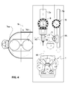
- the machining center illustrated at figure 3 comprises on each side of the machining area, a horizontal machining unit 1,2 with at least one horizontal pin associated respectively with an automatic tool changer 9 and 8.
- the complementary machining unit 3 comprises she a vertical pin with an automatic tool changer 10.
- the first machining unit 1 is a horizontal machining unit with automatic change of multi-spindle cassettes 11.
- the first machining unit 1 with a revolver head is associated with a multi-spindle magazine 12 to automatically change the multi-spindles on the revolver head.
- the workpiece holder 4 comprises means of rotation in two axes: axis V2 for 360 ° rotation and a divider axis H5 which allows precise angular positioning with respect to the machining units 1 or 2 in a pivot angle of between 0 ° and 90 °.
- a pivoting for example of 90 ° makes it easy to machine the fifth face of the workpiece 6 with a machining unit or with a machining unit with a revolver head.
- the means of rotation and pivoting are provided by servo motors.
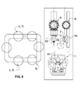
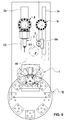
- the machining center illustrated at figure 5 shows a piece 6 fixed on a pallet 13, which will be gripped by the gripping device 5.
- the pallet 13 has for example a fastening portion 13a, in which is held the workpiece 6 and a free portion 13b in which comes s engaging the gripping device 5.
- the connection between the free portion 13b and the gripping device 5 is effected by any known means and in particular complementarity of tool attachment type shapes. Previously, the parts are loosened by the operator when machining is completed and tightened by the operator when placing the blank.
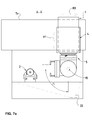
- the machining center comprises a palletizing system 14 at two positions 14a and 14b, in the single zone of loading and unloading.
- An operator performs for example a palletizing of a workpiece 6 at the station 14a while the machining center deposits a machined workpiece 6 mounted on its pallet 13 at the station 14b. It follows rotation permutation 14a stations and 14b on the one hand to the machining center to take a new part 6 rough to machine and secondly to the operator to evacuate the machined part 6, if necessary by separating it from its pallet 13 before palletizing a new piece 6 raw.
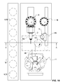
- the machining center according to the invention comprises a magazine 15 of parts 6 or pallets 13 in the loading zone.
- the machining center comprises a single longitudinal conveyor 16, to bring the pieces 6 or pallets 13 raw in the single area of loading and unloading and to evacuate the parts 6 or pallets 13 machined.
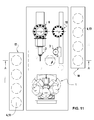
- a first longitudinal conveyor 17 is arranged on one side of the machining center, to bring the pieces 6 or pallets 13 raw into the loading area and a second longitudinal conveyor 18 is disposed on the other side of the machining center , to evacuate the machined parts 6 or pallets 13 from the unloading zone.
- the arrival of a new piece 6 raw in the loading area is thus in masked time during the unloading of the piece 6 previously finished.
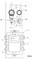
- the exemplary embodiment according to the invention and illustrated in FIG. figure 12 comprises a holding device 19 for stiffening the attachment of the part 6 or the pallet 13 on the workpiece holder 4, so as to avoid bending of the part 6 or the pallet 13 during machining operations.
- the holding device 19 comprises a system 20, retractable and extensible in a vertical direction V3, of the kind against-point counter-spindle or hydraulic clamping engaging with a free face of the part 6 directed downwards. The piece 6 is then held in position at both its low and high ends.
- the translational movement of the holding device 19 is effected by means of a movable carriage 21 mounted on a horizontal rail 21 a.
- the horizontal translation along an axis H6 of the holding device 19 is provided by a servomotor synchronized with a servomotor ensuring the horizontal translation of the workpiece carrier 4 along the axis H3.
- the machining center according to the invention can also comprise, under the machining zone, means for recovery and / or evacuation 22, by gravity, chips and lubricant.
- the recovery and evacuation means 22 may advantageously comprise suction means.
Landscapes
- Engineering & Computer Science (AREA)
- Mechanical Engineering (AREA)
- Machine Tool Units (AREA)
- Automatic Tool Replacement In Machine Tools (AREA)
Priority Applications (2)
| Application Number | Priority Date | Filing Date | Title |
|---|---|---|---|
| AT09156509T ATE521448T1 (de) | 2009-03-27 | 2009-03-27 | Autonomes hochleistungs-bearbeitungszentrum mit vertikaler teileentnahme |
| EP09156509A EP2233247B1 (de) | 2009-03-27 | 2009-03-27 | Autonomes Hochleistungs-Bearbeitungszentrum mit vertikaler Teileentnahme |
Applications Claiming Priority (1)
| Application Number | Priority Date | Filing Date | Title |
|---|---|---|---|
| EP09156509A EP2233247B1 (de) | 2009-03-27 | 2009-03-27 | Autonomes Hochleistungs-Bearbeitungszentrum mit vertikaler Teileentnahme |
Publications (2)
| Publication Number | Publication Date |
|---|---|
| EP2233247A1 true EP2233247A1 (de) | 2010-09-29 |
| EP2233247B1 EP2233247B1 (de) | 2011-08-24 |
Family
ID=41009319
Family Applications (1)
| Application Number | Title | Priority Date | Filing Date |
|---|---|---|---|
| EP09156509A Not-in-force EP2233247B1 (de) | 2009-03-27 | 2009-03-27 | Autonomes Hochleistungs-Bearbeitungszentrum mit vertikaler Teileentnahme |
Country Status (2)
| Country | Link |
|---|---|
| EP (1) | EP2233247B1 (de) |
| AT (1) | ATE521448T1 (de) |
Cited By (3)
| Publication number | Priority date | Publication date | Assignee | Title |
|---|---|---|---|---|
| WO2016188864A1 (de) * | 2015-05-22 | 2016-12-01 | Ffg Werke Gmbh | Werkzeugmaschine mit horizontalen arbeitsspindeln |
| EP3195976A1 (de) * | 2016-01-25 | 2017-07-26 | DECKEL MAHO Pfronten GmbH | Werkzeugmaschine, insbesondere mehrfachspindel-fräsmaschine |
| EP3195977A1 (de) * | 2016-01-25 | 2017-07-26 | DECKEL MAHO Pfronten GmbH | Werkzeugmaschine, insbesondere mehrfachspindel-fräsmaschine |
Citations (5)
| Publication number | Priority date | Publication date | Assignee | Title |
|---|---|---|---|---|
| WO1996000633A1 (de) | 1994-06-29 | 1996-01-11 | Gruener Magnus | Bearbeitungszentrum |
| DE19744157A1 (de) * | 1997-10-07 | 1999-04-08 | Heller Geb Gmbh Maschf | Werkzeugmaschinengruppe mit zwei einander gegenüberstehenden Bearbeitungseinheiten |
| EP1321225A2 (de) * | 2001-12-21 | 2003-06-25 | GROB-Werke Burkhart Grob e.K. | Bearbeitungsanlage mit mindestens einer Transportbahn und mehreren Bearbeitungsstationen |
| EP1346788A2 (de) * | 2002-03-22 | 2003-09-24 | GROB-Werke Burkhart Grob e.K. | Bearbeitungszentrum |
| DE10235518A1 (de) * | 2002-08-05 | 2004-03-04 | Emag Maschinenfabrik Gmbh | Verfahren und Vorrichtung zur Werkstück-Bearbeitung |
-
2009
- 2009-03-27 EP EP09156509A patent/EP2233247B1/de not_active Not-in-force
- 2009-03-27 AT AT09156509T patent/ATE521448T1/de not_active IP Right Cessation
Patent Citations (6)
| Publication number | Priority date | Publication date | Assignee | Title |
|---|---|---|---|---|
| WO1996000633A1 (de) | 1994-06-29 | 1996-01-11 | Gruener Magnus | Bearbeitungszentrum |
| US5781983A (en) * | 1994-06-29 | 1998-07-21 | Gruener; Magnus | Machining center |
| DE19744157A1 (de) * | 1997-10-07 | 1999-04-08 | Heller Geb Gmbh Maschf | Werkzeugmaschinengruppe mit zwei einander gegenüberstehenden Bearbeitungseinheiten |
| EP1321225A2 (de) * | 2001-12-21 | 2003-06-25 | GROB-Werke Burkhart Grob e.K. | Bearbeitungsanlage mit mindestens einer Transportbahn und mehreren Bearbeitungsstationen |
| EP1346788A2 (de) * | 2002-03-22 | 2003-09-24 | GROB-Werke Burkhart Grob e.K. | Bearbeitungszentrum |
| DE10235518A1 (de) * | 2002-08-05 | 2004-03-04 | Emag Maschinenfabrik Gmbh | Verfahren und Vorrichtung zur Werkstück-Bearbeitung |
Cited By (4)
| Publication number | Priority date | Publication date | Assignee | Title |
|---|---|---|---|---|
| WO2016188864A1 (de) * | 2015-05-22 | 2016-12-01 | Ffg Werke Gmbh | Werkzeugmaschine mit horizontalen arbeitsspindeln |
| EP3195976A1 (de) * | 2016-01-25 | 2017-07-26 | DECKEL MAHO Pfronten GmbH | Werkzeugmaschine, insbesondere mehrfachspindel-fräsmaschine |
| EP3195977A1 (de) * | 2016-01-25 | 2017-07-26 | DECKEL MAHO Pfronten GmbH | Werkzeugmaschine, insbesondere mehrfachspindel-fräsmaschine |
| US10322484B2 (en) | 2016-01-25 | 2019-06-18 | Deckel Maho Pfronten Gmbh | Machine tool, in particular multi-spindle milling machine |
Also Published As
| Publication number | Publication date |
|---|---|
| ATE521448T1 (de) | 2011-09-15 |
| EP2233247B1 (de) | 2011-08-24 |
Similar Documents
| Publication | Publication Date | Title |
|---|---|---|
| US9095954B2 (en) | Apparatus for machining an elongated workpiece | |
| EP0368977B1 (de) | Werkzeugmaschine für mehrere bearbeitungsarten und zur komplexen bearbeitung von langen werkstücken | |
| FR2986728A1 (fr) | Machine-outil avec un axe a | |
| JP5741531B2 (ja) | 回転加工機及び回転加工方法 | |
| EP2033725A1 (de) | Vorrichtung zum universellen automatischen Zuführen und Entladen von Werkstücken für Werkzeugmaschine | |
| FR2975619A1 (fr) | Machine-outil a chargement automatique avec broche porte-piece verticale | |
| CN108655494A (zh) | 一种涡轮盘榫槽拉削的自动化生产线 | |
| FR3004371A1 (fr) | Machine-outil a double broche | |
| CH636543A5 (fr) | Machine-outil comprenant deux broches coaxiales opposees. | |
| FR2979068A1 (fr) | Machine-outil a chargement automatique avec deux broches porte-piece verticales | |
| FR2981870A1 (fr) | Machine-outil avec axe y | |
| EP2851171B1 (de) | Schneidevorrichtung für Granit oder andere harte Materialien | |
| CN116619589A (zh) | 开磨一体机及其控制方法及系统、介质、设备 | |
| WO2011039700A1 (en) | Machine for processing material in the form of slabs, in particular natural and agglomerated stone material, ceramic material and glass material | |
| FR2972954A1 (fr) | Machine-outil a double broche | |
| EP2233247B1 (de) | Autonomes Hochleistungs-Bearbeitungszentrum mit vertikaler Teileentnahme | |
| FR3008335A1 (fr) | Procede de changement d'outil et machine-outil avec changeur d'outil | |
| JP5512354B2 (ja) | 棒状ワークの加工方法及びその装置 | |
| EP0032642B2 (de) | Drehbank mit horizontaler Spindel | |
| EP1851001B1 (de) | Transfermaschine zur herstellung von bohrern und bits | |
| FR2462100A1 (fr) | Machine-outil a changement d'outil automatique | |
| EP1509361B1 (de) | Mehrachsiges bearbeitungszentrum mit einer werkstückspindel | |
| US20140106950A1 (en) | Method for Changing a Gear Cutting Tool with Double-Sided Bearing in a Gear Cutting Machine and Device Therefor | |
| EP0468855B1 (de) | Werkzeugschnellwechselanordnung für eine Presse | |
| WO2025153706A1 (fr) | Dispositif de préhension |
Legal Events
| Date | Code | Title | Description |
|---|---|---|---|
| PUAI | Public reference made under article 153(3) epc to a published international application that has entered the european phase |
Free format text: ORIGINAL CODE: 0009012 |
|
| AK | Designated contracting states |
Kind code of ref document: A1 Designated state(s): AT BE BG CH CY CZ DE DK EE ES FI FR GB GR HR HU IE IS IT LI LT LU LV MC MK MT NL NO PL PT RO SE SI SK TR |
|
| AX | Request for extension of the european patent |
Extension state: AL BA RS |
|
| GRAP | Despatch of communication of intention to grant a patent |
Free format text: ORIGINAL CODE: EPIDOSNIGR1 |
|
| 17P | Request for examination filed |
Effective date: 20110217 |
|
| AKX | Designation fees paid |
Designated state(s): AT BE BG CH CY CZ DE DK EE ES FI FR GB GR HR HU IE IS IT LI LT LU LV MC MK MT NL NO PL PT RO SE SI SK TR |
|
| GRAS | Grant fee paid |
Free format text: ORIGINAL CODE: EPIDOSNIGR3 |
|
| GRAA | (expected) grant |
Free format text: ORIGINAL CODE: 0009210 |
|
| AK | Designated contracting states |
Kind code of ref document: B1 Designated state(s): AT BE BG CH CY CZ DE DK EE ES FI FR GB GR HR HU IE IS IT LI LT LU LV MC MK MT NL NO PL PT RO SE SI SK TR |
|
| REG | Reference to a national code |
Ref country code: GB Ref legal event code: FG4D Free format text: NOT ENGLISH |
|
| REG | Reference to a national code |
Ref country code: CH Ref legal event code: EP |
|
| REG | Reference to a national code |
Ref country code: IE Ref legal event code: FG4D Free format text: LANGUAGE OF EP DOCUMENT: FRENCH |
|
| REG | Reference to a national code |
Ref country code: CH Ref legal event code: NV Representative=s name: BOVARD AG |
|
| REG | Reference to a national code |
Ref country code: DE Ref legal event code: R096 Ref document number: 602009002232 Country of ref document: DE Effective date: 20111020 |
|
| REG | Reference to a national code |
Ref country code: NL Ref legal event code: VDEP Effective date: 20110824 |
|
| LTIE | Lt: invalidation of european patent or patent extension |
Effective date: 20110824 |
|
| PG25 | Lapsed in a contracting state [announced via postgrant information from national office to epo] |
Ref country code: PT Free format text: LAPSE BECAUSE OF FAILURE TO SUBMIT A TRANSLATION OF THE DESCRIPTION OR TO PAY THE FEE WITHIN THE PRESCRIBED TIME-LIMIT Effective date: 20111226 Ref country code: FI Free format text: LAPSE BECAUSE OF FAILURE TO SUBMIT A TRANSLATION OF THE DESCRIPTION OR TO PAY THE FEE WITHIN THE PRESCRIBED TIME-LIMIT Effective date: 20110824 Ref country code: IS Free format text: LAPSE BECAUSE OF FAILURE TO SUBMIT A TRANSLATION OF THE DESCRIPTION OR TO PAY THE FEE WITHIN THE PRESCRIBED TIME-LIMIT Effective date: 20111224 Ref country code: LT Free format text: LAPSE BECAUSE OF FAILURE TO SUBMIT A TRANSLATION OF THE DESCRIPTION OR TO PAY THE FEE WITHIN THE PRESCRIBED TIME-LIMIT Effective date: 20110824 Ref country code: NL Free format text: LAPSE BECAUSE OF FAILURE TO SUBMIT A TRANSLATION OF THE DESCRIPTION OR TO PAY THE FEE WITHIN THE PRESCRIBED TIME-LIMIT Effective date: 20110824 Ref country code: SE Free format text: LAPSE BECAUSE OF FAILURE TO SUBMIT A TRANSLATION OF THE DESCRIPTION OR TO PAY THE FEE WITHIN THE PRESCRIBED TIME-LIMIT Effective date: 20110824 Ref country code: HR Free format text: LAPSE BECAUSE OF FAILURE TO SUBMIT A TRANSLATION OF THE DESCRIPTION OR TO PAY THE FEE WITHIN THE PRESCRIBED TIME-LIMIT Effective date: 20110824 Ref country code: NO Free format text: LAPSE BECAUSE OF FAILURE TO SUBMIT A TRANSLATION OF THE DESCRIPTION OR TO PAY THE FEE WITHIN THE PRESCRIBED TIME-LIMIT Effective date: 20111124 |
|
| REG | Reference to a national code |
Ref country code: AT Ref legal event code: MK05 Ref document number: 521448 Country of ref document: AT Kind code of ref document: T Effective date: 20110824 |
|
| PG25 | Lapsed in a contracting state [announced via postgrant information from national office to epo] |
Ref country code: PL Free format text: LAPSE BECAUSE OF FAILURE TO SUBMIT A TRANSLATION OF THE DESCRIPTION OR TO PAY THE FEE WITHIN THE PRESCRIBED TIME-LIMIT Effective date: 20110824 Ref country code: CY Free format text: LAPSE BECAUSE OF FAILURE TO SUBMIT A TRANSLATION OF THE DESCRIPTION OR TO PAY THE FEE WITHIN THE PRESCRIBED TIME-LIMIT Effective date: 20110824 Ref country code: AT Free format text: LAPSE BECAUSE OF FAILURE TO SUBMIT A TRANSLATION OF THE DESCRIPTION OR TO PAY THE FEE WITHIN THE PRESCRIBED TIME-LIMIT Effective date: 20110824 Ref country code: SI Free format text: LAPSE BECAUSE OF FAILURE TO SUBMIT A TRANSLATION OF THE DESCRIPTION OR TO PAY THE FEE WITHIN THE PRESCRIBED TIME-LIMIT Effective date: 20110824 Ref country code: LV Free format text: LAPSE BECAUSE OF FAILURE TO SUBMIT A TRANSLATION OF THE DESCRIPTION OR TO PAY THE FEE WITHIN THE PRESCRIBED TIME-LIMIT Effective date: 20110824 Ref country code: GR Free format text: LAPSE BECAUSE OF FAILURE TO SUBMIT A TRANSLATION OF THE DESCRIPTION OR TO PAY THE FEE WITHIN THE PRESCRIBED TIME-LIMIT Effective date: 20111125 |
|
| REG | Reference to a national code |
Ref country code: IE Ref legal event code: FD4D |
|
| PG25 | Lapsed in a contracting state [announced via postgrant information from national office to epo] |
Ref country code: SK Free format text: LAPSE BECAUSE OF FAILURE TO SUBMIT A TRANSLATION OF THE DESCRIPTION OR TO PAY THE FEE WITHIN THE PRESCRIBED TIME-LIMIT Effective date: 20110824 Ref country code: IE Free format text: LAPSE BECAUSE OF FAILURE TO SUBMIT A TRANSLATION OF THE DESCRIPTION OR TO PAY THE FEE WITHIN THE PRESCRIBED TIME-LIMIT Effective date: 20110824 Ref country code: CZ Free format text: LAPSE BECAUSE OF FAILURE TO SUBMIT A TRANSLATION OF THE DESCRIPTION OR TO PAY THE FEE WITHIN THE PRESCRIBED TIME-LIMIT Effective date: 20110824 |
|
| PGFP | Annual fee paid to national office [announced via postgrant information from national office to epo] |
Ref country code: LU Payment date: 20120328 Year of fee payment: 4 |
|
| PG25 | Lapsed in a contracting state [announced via postgrant information from national office to epo] |
Ref country code: IT Free format text: LAPSE BECAUSE OF FAILURE TO SUBMIT A TRANSLATION OF THE DESCRIPTION OR TO PAY THE FEE WITHIN THE PRESCRIBED TIME-LIMIT Effective date: 20110824 Ref country code: RO Free format text: LAPSE BECAUSE OF FAILURE TO SUBMIT A TRANSLATION OF THE DESCRIPTION OR TO PAY THE FEE WITHIN THE PRESCRIBED TIME-LIMIT Effective date: 20110824 Ref country code: EE Free format text: LAPSE BECAUSE OF FAILURE TO SUBMIT A TRANSLATION OF THE DESCRIPTION OR TO PAY THE FEE WITHIN THE PRESCRIBED TIME-LIMIT Effective date: 20110824 |
|
| PG25 | Lapsed in a contracting state [announced via postgrant information from national office to epo] |
Ref country code: DK Free format text: LAPSE BECAUSE OF FAILURE TO SUBMIT A TRANSLATION OF THE DESCRIPTION OR TO PAY THE FEE WITHIN THE PRESCRIBED TIME-LIMIT Effective date: 20110824 |
|
| PGFP | Annual fee paid to national office [announced via postgrant information from national office to epo] |
Ref country code: BE Payment date: 20120329 Year of fee payment: 4 |
|
| PLBE | No opposition filed within time limit |
Free format text: ORIGINAL CODE: 0009261 |
|
| STAA | Information on the status of an ep patent application or granted ep patent |
Free format text: STATUS: NO OPPOSITION FILED WITHIN TIME LIMIT |
|
| 26N | No opposition filed |
Effective date: 20120525 |
|
| REG | Reference to a national code |
Ref country code: DE Ref legal event code: R097 Ref document number: 602009002232 Country of ref document: DE Effective date: 20120525 |
|
| PG25 | Lapsed in a contracting state [announced via postgrant information from national office to epo] |
Ref country code: MC Free format text: LAPSE BECAUSE OF NON-PAYMENT OF DUE FEES Effective date: 20120331 |
|
| PG25 | Lapsed in a contracting state [announced via postgrant information from national office to epo] |
Ref country code: MK Free format text: LAPSE BECAUSE OF FAILURE TO SUBMIT A TRANSLATION OF THE DESCRIPTION OR TO PAY THE FEE WITHIN THE PRESCRIBED TIME-LIMIT Effective date: 20110824 |
|
| PG25 | Lapsed in a contracting state [announced via postgrant information from national office to epo] |
Ref country code: ES Free format text: LAPSE BECAUSE OF FAILURE TO SUBMIT A TRANSLATION OF THE DESCRIPTION OR TO PAY THE FEE WITHIN THE PRESCRIBED TIME-LIMIT Effective date: 20111205 |
|
| PGFP | Annual fee paid to national office [announced via postgrant information from national office to epo] |
Ref country code: CH Payment date: 20130307 Year of fee payment: 5 |
|
| PG25 | Lapsed in a contracting state [announced via postgrant information from national office to epo] |
Ref country code: BG Free format text: LAPSE BECAUSE OF FAILURE TO SUBMIT A TRANSLATION OF THE DESCRIPTION OR TO PAY THE FEE WITHIN THE PRESCRIBED TIME-LIMIT Effective date: 20111124 |
|
| PG25 | Lapsed in a contracting state [announced via postgrant information from national office to epo] |
Ref country code: MT Free format text: LAPSE BECAUSE OF FAILURE TO SUBMIT A TRANSLATION OF THE DESCRIPTION OR TO PAY THE FEE WITHIN THE PRESCRIBED TIME-LIMIT Effective date: 20110824 |
|
| BERE | Be: lapsed |
Owner name: EMISSA S.A. Effective date: 20130331 |
|
| PG25 | Lapsed in a contracting state [announced via postgrant information from national office to epo] |
Ref country code: BE Free format text: LAPSE BECAUSE OF NON-PAYMENT OF DUE FEES Effective date: 20130331 |
|
| PG25 | Lapsed in a contracting state [announced via postgrant information from national office to epo] |
Ref country code: TR Free format text: LAPSE BECAUSE OF FAILURE TO SUBMIT A TRANSLATION OF THE DESCRIPTION OR TO PAY THE FEE WITHIN THE PRESCRIBED TIME-LIMIT Effective date: 20110824 |
|
| PG25 | Lapsed in a contracting state [announced via postgrant information from national office to epo] |
Ref country code: HU Free format text: LAPSE BECAUSE OF FAILURE TO SUBMIT A TRANSLATION OF THE DESCRIPTION OR TO PAY THE FEE WITHIN THE PRESCRIBED TIME-LIMIT Effective date: 20090327 |
|
| REG | Reference to a national code |
Ref country code: CH Ref legal event code: PL |
|
| PG25 | Lapsed in a contracting state [announced via postgrant information from national office to epo] |
Ref country code: LI Free format text: LAPSE BECAUSE OF NON-PAYMENT OF DUE FEES Effective date: 20140331 Ref country code: CH Free format text: LAPSE BECAUSE OF NON-PAYMENT OF DUE FEES Effective date: 20140331 |
|
| PG25 | Lapsed in a contracting state [announced via postgrant information from national office to epo] |
Ref country code: LU Free format text: LAPSE BECAUSE OF NON-PAYMENT OF DUE FEES Effective date: 20130327 |
|
| REG | Reference to a national code |
Ref country code: FR Ref legal event code: PLFP Year of fee payment: 8 |
|
| PGFP | Annual fee paid to national office [announced via postgrant information from national office to epo] |
Ref country code: GB Payment date: 20160321 Year of fee payment: 8 Ref country code: FR Payment date: 20160321 Year of fee payment: 8 |
|
| PGFP | Annual fee paid to national office [announced via postgrant information from national office to epo] |
Ref country code: DE Payment date: 20160330 Year of fee payment: 8 |
|
| REG | Reference to a national code |
Ref country code: DE Ref legal event code: R119 Ref document number: 602009002232 Country of ref document: DE |
|
| GBPC | Gb: european patent ceased through non-payment of renewal fee |
Effective date: 20170327 |
|
| REG | Reference to a national code |
Ref country code: FR Ref legal event code: ST Effective date: 20171130 |
|
| PG25 | Lapsed in a contracting state [announced via postgrant information from national office to epo] |
Ref country code: FR Free format text: LAPSE BECAUSE OF NON-PAYMENT OF DUE FEES Effective date: 20170331 Ref country code: DE Free format text: LAPSE BECAUSE OF NON-PAYMENT OF DUE FEES Effective date: 20171003 |
|
| PG25 | Lapsed in a contracting state [announced via postgrant information from national office to epo] |
Ref country code: GB Free format text: LAPSE BECAUSE OF NON-PAYMENT OF DUE FEES Effective date: 20170327 |