EP2233372A1 - Agencement de coussin d'air pour un véhicule automobile et procédé de fabrication d'un agencement de coussin d'air - Google Patents
Agencement de coussin d'air pour un véhicule automobile et procédé de fabrication d'un agencement de coussin d'air Download PDFInfo
- Publication number
- EP2233372A1 EP2233372A1 EP10155034A EP10155034A EP2233372A1 EP 2233372 A1 EP2233372 A1 EP 2233372A1 EP 10155034 A EP10155034 A EP 10155034A EP 10155034 A EP10155034 A EP 10155034A EP 2233372 A1 EP2233372 A1 EP 2233372A1
- Authority
- EP
- European Patent Office
- Prior art keywords
- cover
- component
- predetermined breaking
- airbag
- teeth
- Prior art date
- Legal status (The legal status is an assumption and is not a legal conclusion. Google has not performed a legal analysis and makes no representation as to the accuracy of the status listed.)
- Granted
Links
Images

Classifications
-
- B—PERFORMING OPERATIONS; TRANSPORTING
- B60—VEHICLES IN GENERAL
- B60R—VEHICLES, VEHICLE FITTINGS, OR VEHICLE PARTS, NOT OTHERWISE PROVIDED FOR
- B60R21/00—Arrangements or fittings on vehicles for protecting or preventing injuries to occupants or pedestrians in case of accidents or other traffic risks
- B60R21/02—Occupant safety arrangements or fittings, e.g. crash pads
- B60R21/16—Inflatable occupant restraints or confinements designed to inflate upon impact or impending impact, e.g. air bags
- B60R21/20—Arrangements for storing inflatable members in their non-use or deflated condition; Arrangement or mounting of air bag modules or components
- B60R21/215—Arrangements for storing inflatable members in their non-use or deflated condition; Arrangement or mounting of air bag modules or components characterised by the covers for the inflatable member
- B60R21/2165—Arrangements for storing inflatable members in their non-use or deflated condition; Arrangement or mounting of air bag modules or components characterised by the covers for the inflatable member characterised by a tear line for defining a deployment opening
- B60R2021/21652—Arrangements for storing inflatable members in their non-use or deflated condition; Arrangement or mounting of air bag modules or components characterised by the covers for the inflatable member characterised by a tear line for defining a deployment opening the tearing being done or assisted by cutters
Definitions
- the invention relates to an airbag assembly for a motor vehicle and a method for producing an airbag assembly according to the preambles of claims 1 and 13.
- airbag assemblies are known from a variety of documents, for example DE 195 16 230 C2 ; DE 10 2006 054 590 B3 ; EP 0 428 935 B1 and EP 0 741 062 B1 ,
- the known airbag assemblies which are typically used as a frontal or side impact protection in a motor vehicle, include an airbag impact pad and associated operating equipment housed in a receiving space of a support member, such as in the instrument panel of a motor vehicle.
- the receiving space is covered by a cover, which can be manufactured as a molded part together with the support member.
- the cover and the carrier component for example a carrier of an instrument panel, are connected to one another, predetermined breaking points being formed between the cover and the carrier component.
- Such airbag arrangements are installed, for example, in the steering wheel of a motor vehicle and, on the passenger side, in the instrument panel. It is also known to incorporate airbag devices in the doors as side impact protection. All the known airbag arrangements are covered by covers made of plastic or foamed metal parts, which are generally referred to as a molded part, these covers are provided with predetermined breaking points, which break at an airbag deployment and proper leakage of the impact pad, which lies under the cover, guarantee. The predetermined breaking points are dimensioned so that a defined tear behavior is achieved at a predetermined breaking strength.
- a covering material such as a cover made of genuine leather or synthetic leather, plastic films, hides and the like. This cover material spans both the support member and the cover.
- the documents DE 197 38493 A1 and US Pat. No. 6,942,243 B2 show airbag covers, which have at their edge a kind of rotating cutting blade, the airbag cover protrudes upward in the direction of the cover material and cuts into the covering material when the airbag is triggered.
- the US 5,466,000 shows an airbag cover with a cutting edge, wherein the entire edge of the airbag cover has teeth that project upwards at an angle of 90 degrees from the airbag cover and cut into the covering material.
- the US 5,375,875 shows an airbag cover with individual cutting tips, which also project from the airbag cover upwards to cut into the cover material.
- the last described airbag covers thus have separate cutting aids projecting from the cover at an angle upwards, in the direction of the cover material. These cutting aids require an additional manufacturing cut and involve the risk of injury when a passenger hits the airbag cover with his or her head or other body part. The cutting aids would be punched in the head of a forehead of the passenger.
- the invention provides an airbag arrangement, in particular for use in a motor vehicle, with a carrier component with integrated cover component.
- the cover member covers in the closed position a receiving space for an airbag impact cushion and dissolves when the airbag is triggered at least partially from the support member to release the receiving space.
- the cover component and the carrier component are covered with a cover material.
- at least one tooth is formed on the edge of the cover component, which tooth extends from the edge of the cover component in its plane and which tears the cover material when the cover component is detached from the carrier component.
- this at least one tooth is preferably cut free along a predetermined breaking line, which is formed between the cover component and the carrier component.
- the invention thus provides a cutting aids for which no extra component and no separate manufacturing step is required, but this cutting aid is formed in the formation of the predetermined breaking line or tear seam between the support member and cover component quasi as a "byproduct".
- the invention has the great advantage that the tooth or teeth are oriented in the direction of the plane of the carrier and not in the direction of the cover material, which is to be torn open. As a result, injuries due to protruding cutting aids can be avoided.
- the teeth along the edge of the cover component are formed such that they tear the cover material defined upon release of the cover component of the support member, without the cover material would have a structural weakening in the region of the predetermined breaking line.
- the cover of the airbag impact cushion thus after tearing the cover along the predetermined breaking line on one or more of its edge protruding teeth, which penetrate upon pressing the cover into the cover material and at predetermined points generate one or more initial cracks, to a defined Rip open the cover material.
- a pre-weakening of the cover material by cutting or the like is not necessary.
- the lid member is connected to the support member at an edge via a hinge member, such as a living hinge or a flexible tether, and the tooth or teeth are formed in the region of the hinge member opposite edge of the lid member.
- a hinge member such as a living hinge or a flexible tether
- teeth may also be provided on the side edges of the lid member.
- the teeth may be in the form of substantially triangular or trapezoidal protrusions. You should have at least one of the edge of the lid component projecting tip. It is also possible to provide a series of small teeth side by side in the manner of a serrated blade of a knife blade. In a preferred embodiment of the invention, at least one tooth is formed undercut, wherein its cutting edge with the surface of the support member forms an angle 1 90 °. This does not mean that the teeth protrude from the plane of the lid member, but that the cutting edges of the teeth are bevelled, for example. In practice, this can be realized by the predetermined breaking line is not cut perpendicularly but obliquely to the surface of the support member in this. As a result, the cutting ability of the teeth can be optimized.
- the teeth can have any shape which is suitable for generating initial cracks during the tearing of the cover component along the predetermined breaking line in the covering material, which leads to a defined tearing of the covering material.
- different, differently shaped teeth can be provided. The toes are therefore not set to the shapes shown.
- the predetermined breaking line should be designed such that the tooth tips are completely exposed.
- the number, arrangement and shape of the teeth depends on the size of the cover component and the selected materials and material thicknesses of both the support member and the cover member and the cover material.
- at least one tooth is provided.
- the invention may be formed on the edge of the lid member three to eleven teeth, wherein at least in the middle and / or at each corner of the hinge element opposite edge of the lid member, a tooth is provided.
- two, three or four teeth are formed at the two corners and one, two or three teeth are formed in the region between the two corners.
- the cover component and the carrier component are integrally formed as injection molded parts, wherein the predetermined breaking line is produced by laser cutting or water jet cutting. It is also conceivable to mold the predetermined breaking line in the production of the carrier component in this.
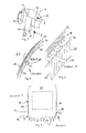
- Fig. 1 shows an isometric view of an instrument panel 10 of a motor vehicle with an area for display instruments 12 on the driver side and an area for an air bag 14 as a frontal impact protection on the passenger side.
- the area for the airbag 14 has a receiving space for the airbag impact cushion, operating devices of the airbag and a cover of the receiving space, which in Fig. 1 not shown in detail.
- the coupling of a receiving space for an airbag impact pad and the associated operating devices below the instrument panel is basically known from the prior art and shown, for example, in the following publications: DE 298 11 739 U1 ; DE 100 32 104 A1 ; DE 102 53 185 A1 ; and DE 2006 008 564 A1 ,
- the instrument panel is usually constructed with a one- or multi-part support member 24 which defines the contour of the instrument panel 10 and in which the various display and control devices and an airbag module can be integrated.
- the airbag module consists of the airbag impact pad and operating equipment, such as a hot or cold gas generator, an acceleration sensor, a trip unit, etc.
- the receiving space for the airbag impact pad is disposed below the region 14 and covered by a cover member 22.
- the lid member 22 and the support member 24 are formed in the preferred embodiment of the invention from a single molded part, for example by injection molding of plastic or molding a plate material or pressing a fiber or plastic material.
- the molded part which forms the carrier component 24 and the cover component 22, can be produced from a natural fiber or a plastic and more generally from thermoplastics or thermosets or a combination of thermosets and thermosets and fiber.
- a predetermined breaking line 26 is formed between the cover member 22 and the support member 24, which ensures a defined tearing of the cover member 22 when the airbag impact pad under the cover member 22.
- the predetermined breaking line can be formed for example by laser cutting or water jet cutting. This is described below with further details.
- a steering wheel 16 a center console 18 and a shift lever 20 are indicated schematically.
- the carrier component 24 of the instrument panel and the cover component 22 are covered with a cover material 28 which, in the embodiment shown, is constructed in two layers with a soft foam layer 30 and a decorative layer 32.
- the foam layer 30 may include, for example, a PU foam
- the decorative layer 32 may be made of a leather, synthetic leather, a plastic film, a slush skin, or the like.
- the cover material 28 is not modified in the region of the predetermined breaking line 26 and in particular has no weakening in the region of the predetermined breaking line 26.
- the cover material 30 is applied to the support member 24 and the cover member 22, e.g. laminated.
- the cover component 22 is delimited from the carrier component 24 by the predetermined breaking line 26, which in FIG Fig. 4 is shown schematically.
- the predetermined breaking line 26 is designed such that the cover part 22 is permanently connected to the carrier component 24 via a hinge region 34.
- This hinge region 34 can simply be formed by a seamless transition from the cover component 22 to the carrier component 24 or comprise a film hinge, which is formed by a material thickness reduction between a longitudinal edge of the lid component 22 and the carrier component 24. He can be a hinge on the basis of an embedded fabric tape or other type of hinge that allows the lid member 22 to pop open upon deployment of the airbag.
- the predetermined breaking line 26 is formed between the cover component 22 and the carrier component 24 such that the edge of the cover component 22 has teeth 42, 44 which, when the lid component 22 is detached from the Support member 24 tear the cover material 38 over the lid member.
- the teeth 42, 44 should be formed on the longitudinal edge 36 of the cover component 22 opposite the hinge region 34 and in particular in the middle of the longitudinal edge 36 and / or in the region of the two corners 46, 48 adjoining the longitudinal edge 36.
- 22 teeth can also be formed on the side edges 38, 40 of the cover component.
- the cover component 22 has three teeth 42 in the region of the corners 46, 48 and two teeth 44 along the longitudinal edge 36 lying between the corners.
- the invention is not limited to the arrangement of the teeth 42, 44 shown, and it may be provided in the region of the corners 48, 46 one, two, three, four, five teeth or a number of teeth 42, while at the intermediate Longitudinal edge 36 one, two, three, four teeth or a different number of teeth can be provided.
- a lid member 22 with only one tooth, e.g. in the central region of the longitudinal edge 36, is within the scope of the invention.
- the teeth are formed as triangular projections, but they may also be trapezoidal, parabolic or hyperbolic, forked or otherwise shaped, preferably each tooth has at least one of the edge 36, 38, 40 of the cover member 22 projecting tip. It is also possible to provide a corrugation in the manner of a serrated edge on the edge 36, 38, 40 of the cover component.
- the teeth 44 and / or 42 are undercut, so that their cutting edges 50 with the surface of the cover member 22 form an angle which deviates from 90 °.
- the side surfaces of the teeth are inclined, so that there is a trapezoidal cross-section of the teeth in Fig. 5 for one of the teeth 44 is indicated by hatching.
- the inclination of the cutting edges 50 and optionally the side surface of the teeth 44 and / or 42 opposite the surface of the cover component 22 is at an angle between 0 ° and 90 °, preferably between 30 ° and 60 °, for example at approximately 30 °, 40 °, 45 °, 50 ° or 60 °,
- a tooth tip is defined, which can achieve a precise incision in the cover material and thus a defined initial crack in the cover material upon deployment of the airbag.
- all or some of the teeth 42, 44 can be formed with the oblique cutting edges 50 shown by the predetermined breaking line for delimiting the cover member 22 is cut obliquely into the support member as in the FIGS. 2 and 3 indicated.
- teeth 42, 44 will depend on the dimensions of the lid member 22 and the materials and thicknesses of both the lid member 22 and the carrier member 24, as well as the cover material 28.
- the predetermined breaking line 26 is in a preferred embodiment of the invention by subsequent machining of a molding forming the support member 24 and the cover member 22, e.g. produced by laser cutting. Instead of a laser, for example, a knife or a water jet for cutting the predetermined breaking line 26 can be used for processing the molded part.
- the predetermined breaking line 26 is produced before the cover material 28 is applied to the carrier component 24 and the cover component 22. If the teeth are to be formed undercut, the cutting tool can be attached with a corresponding angle to the surface of the molding.
- the predetermined breaking line 26, which in the FIG. 4 is shown as a solid line, in practice consists of a series of spaced apart small cuts or points, wherein in each case a tooth 42, 44 is at least partially, preferably completely cut free.
- the spacing of the individual cuts or perforation points in turn depends on the parameters mentioned above: size of the cover component, material and material thickness.
- Fig. 6 shows a schematic plan view of a support member 24 with integrated cover member 22 according to the invention.
- the lid member 22 is delimited from the support member 24 by the predetermined breaking line 26, which may be made from a number of spaced individual cuts or perforation points.
- the teeth 42, 44 through the Predetermined breaking line 26 is essentially completely cut free. Deviating from the illustration in Fig. 4 For example, the teeth 42, 44 in their foot area can not be cut free or even cut free. Thus, it is possible to cut each closely spaced teeth by means of a single continuous cutting line.
- the exact formation of the predetermined breaking line 26 depends on the materials and requirements used.
- Fig. 6 is indicated by the offset same hatching that the support member 24 are formed in the lid member 22 from one and the same molding, wherein they are defined by the predetermined breaking line 26 from each other. The hatching offset should better identify the two components as well as the hinge area 34.
- the teeth 42, 44 are arranged on the lid member 22 and formed so that when tearing the predetermined breaking line 26 and the pressing out of the lid member 22 when the airbag is triggered, the tips of the teeth 42, 44 in the lid material 28 generate initial cracks which produce a defined rupture of the cover material 28 following the predetermined breaking line 26.
- a weakening or other processing of the cover material 28 with regard to the tear behavior upon deployment of the airbag is not necessary, but may be additionally provided.
Landscapes
- Engineering & Computer Science (AREA)
- Mechanical Engineering (AREA)
- Air Bags (AREA)
Applications Claiming Priority (1)
| Application Number | Priority Date | Filing Date | Title |
|---|---|---|---|
| DE102009014449A DE102009014449A1 (de) | 2009-03-23 | 2009-03-23 | Airbag-Anordnung für ein Kraftfahrzeug und Verfahren zur Herstellung einer Airbag-Anordnung |
Publications (2)
| Publication Number | Publication Date |
|---|---|
| EP2233372A1 true EP2233372A1 (fr) | 2010-09-29 |
| EP2233372B1 EP2233372B1 (fr) | 2011-09-07 |
Family
ID=42238823
Family Applications (1)
| Application Number | Title | Priority Date | Filing Date |
|---|---|---|---|
| EP10155034A Active EP2233372B1 (fr) | 2009-03-23 | 2010-03-01 | Agencement de coussin d'air pour un véhicule automobile et procédé de fabrication d'un agencement de coussin d'air |
Country Status (4)
| Country | Link |
|---|---|
| EP (1) | EP2233372B1 (fr) |
| AT (1) | ATE523388T1 (fr) |
| DE (2) | DE102009014449A1 (fr) |
| ES (1) | ES2369651T3 (fr) |
Cited By (4)
| Publication number | Priority date | Publication date | Assignee | Title |
|---|---|---|---|---|
| WO2012094614A2 (fr) | 2011-01-07 | 2012-07-12 | Johnson Controls Technology Company | Système de déploiement d'airbag pour un panneau intérieur de véhicule enveloppé de tissu |
| CN102795190A (zh) * | 2011-05-26 | 2012-11-28 | 国际汽车配件集团有限公司 | 特别是用于汽车安全气囊的安全气囊盖及其制造方法 |
| FR3000449A1 (fr) * | 2012-12-27 | 2014-07-04 | Faurecia Interieur Ind | Piece d'habillage interieur de vehicule adaptee pour recouvrir un coussin de securite gonflable |
| EP3350027A4 (fr) * | 2015-09-16 | 2019-02-20 | Faurecia (China) Holding Co., Ltd. | Dispositif de recouvrement de coussin de sécurité gonflable |
Families Citing this family (4)
| Publication number | Priority date | Publication date | Assignee | Title |
|---|---|---|---|---|
| DE102010054574A1 (de) * | 2010-12-15 | 2012-06-21 | Volkswagen Ag | Airbagabdeckung an einem Innenausstattungsteil, insbesondere an einer Instrumenententafel eines Fahrzeugs |
| DE102013114015A1 (de) * | 2013-12-13 | 2015-06-18 | Dr. Ing. H.C. F. Porsche Aktiengesellschaft | Airbagdeckel sowie Verwendung eines Sandwich-Kunststoffverbundbauteils |
| DE102017209882A1 (de) | 2017-06-12 | 2018-12-13 | Volkswagen Aktiengesellschaft | Verkleidungsteil für ein Kraftfahrzeug |
| DE102024116334A1 (de) * | 2024-06-11 | 2025-12-11 | Lisa Dräxlmaier GmbH | Innenausstattungsteil für eine airbaganordnung in einem kraftfahrzeug, airbaganordnung und verfahren zum herstellen eines innenausstattungsteils |
Citations (8)
| Publication number | Priority date | Publication date | Assignee | Title |
|---|---|---|---|---|
| DE4241728A1 (fr) * | 1991-12-11 | 1993-06-17 | Takata Corp | |
| US5375875A (en) | 1993-10-05 | 1994-12-27 | Tip Engineering Group, Inc. | Two stage cutter arrangement for forming an air bag deployment opening |
| US5466000A (en) | 1994-11-17 | 1995-11-14 | Morton International, Inc. | Flat-lying cutter/ripper foldable into upstanding position during deployment of a vehicle airbag for detaching a deployment door from a panel |
| EP0788938A2 (fr) | 1995-09-07 | 1997-08-13 | Morton International, Inc. | Dispositif pour améliorer le détachement du couvercle de déploiement d'un système à sac gonflable |
| DE19738493A1 (de) * | 1996-09-07 | 1998-03-12 | Volkswagen Ag | Airbagabdeckung |
| FR2782302A1 (fr) * | 1998-08-13 | 2000-02-18 | Sommer Allibert Lignotock | Planche de bord equipee d'un coussin gonflable de securite dispose dans un boitier |
| DE10344401A1 (de) * | 2003-09-25 | 2005-05-12 | Bayerische Motoren Werke Ag | Airbaganordnung, bei der die Airbagabdeckung scharfe Schwächungsabschnitte zum Auftreten der Dekorschicht aufweist |
| US6942243B2 (en) * | 2002-12-23 | 2005-09-13 | Lear Corporation | Vehicle instrument panel air bag door assembly |
Family Cites Families (8)
| Publication number | Priority date | Publication date | Assignee | Title |
|---|---|---|---|---|
| US5082310A (en) | 1989-11-06 | 1992-01-21 | Tip Engineering Group, Inc. | Arrangement for providing an air bag deployment opening |
| US5316335A (en) * | 1992-12-14 | 1994-05-31 | Davidson Textron Inc. | Self piercing cover assembly air bag |
| DE19516230C2 (de) | 1995-05-03 | 1999-04-01 | Eldra Kunststofftechnik Gmbh | Airbag-Abdeckung sowie Verfahren zu seiner Herstellung |
| DE29811739U1 (de) | 1998-07-01 | 1998-08-13 | Delphi Automotive Systems Deutschland GmbH, 42369 Wuppertal | Armaturentafel |
| DE10032104A1 (de) | 2000-07-01 | 2002-01-10 | Bayerische Motoren Werke Ag | Abdeckung für den Beifahrer-Airbag |
| DE10253185A1 (de) | 2002-11-15 | 2004-06-03 | Autoliv Development Ab | Instrumententafel für ein Kraftfahrzeug mit einer in einer Lüftungsanordnung integrierten Airbageinrichtung |
| DE102006008564B4 (de) | 2006-02-22 | 2009-06-10 | Peguform Gmbh | Luftsackführung mit Abdeckung |
| DE102006054590B3 (de) | 2006-11-20 | 2008-01-31 | Lisa Dräxlmaier GmbH | Funktionsoptimiertes Schwächen eines Abstandsgewirkes |
-
2009
- 2009-03-23 DE DE102009014449A patent/DE102009014449A1/de not_active Withdrawn
-
2010
- 2010-03-01 DE DE202010017301U patent/DE202010017301U1/de not_active Expired - Lifetime
- 2010-03-01 ES ES10155034T patent/ES2369651T3/es active Active
- 2010-03-01 AT AT10155034T patent/ATE523388T1/de active
- 2010-03-01 EP EP10155034A patent/EP2233372B1/fr active Active
Patent Citations (8)
| Publication number | Priority date | Publication date | Assignee | Title |
|---|---|---|---|---|
| DE4241728A1 (fr) * | 1991-12-11 | 1993-06-17 | Takata Corp | |
| US5375875A (en) | 1993-10-05 | 1994-12-27 | Tip Engineering Group, Inc. | Two stage cutter arrangement for forming an air bag deployment opening |
| US5466000A (en) | 1994-11-17 | 1995-11-14 | Morton International, Inc. | Flat-lying cutter/ripper foldable into upstanding position during deployment of a vehicle airbag for detaching a deployment door from a panel |
| EP0788938A2 (fr) | 1995-09-07 | 1997-08-13 | Morton International, Inc. | Dispositif pour améliorer le détachement du couvercle de déploiement d'un système à sac gonflable |
| DE19738493A1 (de) * | 1996-09-07 | 1998-03-12 | Volkswagen Ag | Airbagabdeckung |
| FR2782302A1 (fr) * | 1998-08-13 | 2000-02-18 | Sommer Allibert Lignotock | Planche de bord equipee d'un coussin gonflable de securite dispose dans un boitier |
| US6942243B2 (en) * | 2002-12-23 | 2005-09-13 | Lear Corporation | Vehicle instrument panel air bag door assembly |
| DE10344401A1 (de) * | 2003-09-25 | 2005-05-12 | Bayerische Motoren Werke Ag | Airbaganordnung, bei der die Airbagabdeckung scharfe Schwächungsabschnitte zum Auftreten der Dekorschicht aufweist |
Cited By (13)
| Publication number | Priority date | Publication date | Assignee | Title |
|---|---|---|---|---|
| US9016716B2 (en) | 2011-01-07 | 2015-04-28 | Johnson Controls Technology Company | Airbag deployment system for a fabric wrapped vehicle interior panel |
| WO2012094614A3 (fr) * | 2011-01-07 | 2012-08-30 | Johnson Controls Technology Company | Système de déploiement d'airbag pour un panneau intérieur de véhicule enveloppé de tissu |
| US9707919B2 (en) | 2011-01-07 | 2017-07-18 | Johnson Controls Technology Company | Vehicle interior panel |
| WO2012094614A2 (fr) | 2011-01-07 | 2012-07-12 | Johnson Controls Technology Company | Système de déploiement d'airbag pour un panneau intérieur de véhicule enveloppé de tissu |
| EP2952393A3 (fr) * | 2011-01-07 | 2016-02-10 | Johnson Controls Technology Company | Système de déploiement d'airbag pour un panneau intérieur de véhicule enroulé dans un tissu |
| JP2014501664A (ja) * | 2011-01-07 | 2014-01-23 | ジョンソン コントロールズ テクノロジー カンパニー | 布地で包まれた車両インテリアパネルのためのエアバッグ展開システム |
| EP2527208A1 (fr) | 2011-05-26 | 2012-11-28 | International Automotive Components Group GmbH | Recouvrement d'airbag, notamment pour airbags dans un véhicule automobile et son procédé de fabrication |
| US8517416B2 (en) | 2011-05-26 | 2013-08-27 | International Automotive Components Group Gmbh | Airbag cover, in particular for an airbag in a motor vehicle and a method for the manufacture thereof |
| CN102795190B (zh) * | 2011-05-26 | 2016-08-03 | 国际汽车配件集团有限公司 | 特别是用于汽车安全气囊的安全气囊盖及其制造方法 |
| CN102795190A (zh) * | 2011-05-26 | 2012-11-28 | 国际汽车配件集团有限公司 | 特别是用于汽车安全气囊的安全气囊盖及其制造方法 |
| FR3000449A1 (fr) * | 2012-12-27 | 2014-07-04 | Faurecia Interieur Ind | Piece d'habillage interieur de vehicule adaptee pour recouvrir un coussin de securite gonflable |
| US9022418B2 (en) | 2012-12-27 | 2015-05-05 | Faurecia Interieur Industrie | Interior trim component for motor vehicle, adapted for covering an airbag |
| EP3350027A4 (fr) * | 2015-09-16 | 2019-02-20 | Faurecia (China) Holding Co., Ltd. | Dispositif de recouvrement de coussin de sécurité gonflable |
Also Published As
| Publication number | Publication date |
|---|---|
| ATE523388T1 (de) | 2011-09-15 |
| ES2369651T3 (es) | 2011-12-02 |
| DE202010017301U1 (de) | 2011-10-05 |
| EP2233372B1 (fr) | 2011-09-07 |
| DE102009014449A1 (de) | 2010-10-07 |
Similar Documents
| Publication | Publication Date | Title |
|---|---|---|
| EP2527208B1 (fr) | Recouvrement d'airbag, notamment pour airbags dans un véhicule automobile et son procédé de fabrication | |
| EP2233372B1 (fr) | Agencement de coussin d'air pour un véhicule automobile et procédé de fabrication d'un agencement de coussin d'air | |
| EP0846068B1 (fr) | Habillage en matiere plastique pour vehicule equipe de coussins gonflables, ainsi que dispositif et procede pour sa fabrication | |
| DE60309573T2 (de) | Airbagtür und herstellungsverfahren dafür | |
| DE69912524T2 (de) | Verfahren zum Herstellen eines Kraftfahrzeugverkleidungsteils mit Schwächungslinien für eine Airbag-Entfaltungsöffnung | |
| DE69627259T2 (de) | Luftsackabdeckung und Herstellungsverfahren dafür | |
| DE60121730T2 (de) | Fahrzeug airbagöffnung mit drei schichten und jeweils eine mechanische bruchstelle | |
| DE19819573B4 (de) | Instrumententafel | |
| EP1161362B1 (fr) | Ligne de pointilles pratiquee dans les couvercles d'unites sacs gonflables | |
| DE19651532A1 (de) | Airbag-Abdeckung | |
| EP1084052B1 (fr) | Partie de vehicule comportant un airbag et procede de fabrication d'une telle partie de vehicule | |
| EP1745989B1 (fr) | Couvercle pour airbag avec ligne de rupture invisible | |
| DE4418582C2 (de) | Instrumententafel in einem Kraftwagen | |
| DE112012005244B4 (de) | Verfahren zum Herstellen eines Fahrzeuginnenpaneels mit unsichtbarer Airbagreißnaht sowie Fahrzeuginnenpaneel mit unsichtbarer Airbagreißnaht und Fahrzeugarmaturenbrett aufweisend ein Fahrzeuginnenpaneel mit unsichtbarer Airbagreißnaht | |
| DE10324248A1 (de) | Kunststoffträger und Verfahren zu seiner Herstellung | |
| DE10241715B4 (de) | Fahrzeuginnenverkleidungsteil mit einer Schwächung in einer Airbagabdeckung | |
| WO2003033313A1 (fr) | Piece de revetement interieur pour vehicules automobiles | |
| DE102009048893B4 (de) | Airbagabdeckung | |
| DE102021113280A1 (de) | Abdeckung für eine Airbag-Einrichtung, Innenverkleidungsteil und Verfahren zur Herstellung einer Abdeckung | |
| DE10020525A1 (de) | Airbagabdeckung | |
| EP1392551B1 (fr) | Dispositif pour recouvrir un coussin gonflable de securite et son procede de production | |
| DE10023651A1 (de) | In ein Innenverkleidungsteil für Kraftfahrzeuge integriertes Airbag-System | |
| DE102009032580B4 (de) | Abdeckung für einen Airbag | |
| EP1106446A1 (fr) | Coussin de sécurité intégré dans une garniture de l'habitacle d'un véhicule automobile | |
| AT406759B (de) | Abdeckung für ein airbag-modul |
Legal Events
| Date | Code | Title | Description |
|---|---|---|---|
| PUAI | Public reference made under article 153(3) epc to a published international application that has entered the european phase |
Free format text: ORIGINAL CODE: 0009012 |
|
| AK | Designated contracting states |
Kind code of ref document: A1 Designated state(s): AT BE BG CH CY CZ DE DK EE ES FI FR GB GR HR HU IE IS IT LI LT LU LV MC MK MT NL NO PL PT RO SE SI SK SM TR |
|
| AX | Request for extension of the european patent |
Extension state: AL BA ME RS |
|
| GRAP | Despatch of communication of intention to grant a patent |
Free format text: ORIGINAL CODE: EPIDOSNIGR1 |
|
| 17P | Request for examination filed |
Effective date: 20110223 |
|
| RIC1 | Information provided on ipc code assigned before grant |
Ipc: B60R 21/205 20110101AFI20110331BHEP |
|
| GRAS | Grant fee paid |
Free format text: ORIGINAL CODE: EPIDOSNIGR3 |
|
| GRAA | (expected) grant |
Free format text: ORIGINAL CODE: 0009210 |
|
| REG | Reference to a national code |
Ref country code: GB Ref legal event code: FG4D Free format text: NOT ENGLISH |
|
| REG | Reference to a national code |
Ref country code: CH Ref legal event code: EP |
|
| REG | Reference to a national code |
Ref country code: IE Ref legal event code: FG4D Free format text: LANGUAGE OF EP DOCUMENT: GERMAN |
|
| REG | Reference to a national code |
Ref country code: DE Ref legal event code: R096 Ref document number: 502010000104 Country of ref document: DE Effective date: 20111027 |
|
| REG | Reference to a national code |
Ref country code: RO Ref legal event code: EPE |
|
| REG | Reference to a national code |
Ref country code: ES Ref legal event code: FG2A Ref document number: 2369651 Country of ref document: ES Kind code of ref document: T3 Effective date: 20111202 |
|
| REG | Reference to a national code |
Ref country code: SE Ref legal event code: TRGR |
|
| REG | Reference to a national code |
Ref country code: NL Ref legal event code: VDEP Effective date: 20110907 |
|
| PG25 | Lapsed in a contracting state [announced via postgrant information from national office to epo] |
Ref country code: LT Free format text: LAPSE BECAUSE OF FAILURE TO SUBMIT A TRANSLATION OF THE DESCRIPTION OR TO PAY THE FEE WITHIN THE PRESCRIBED TIME-LIMIT Effective date: 20110907 Ref country code: FI Free format text: LAPSE BECAUSE OF FAILURE TO SUBMIT A TRANSLATION OF THE DESCRIPTION OR TO PAY THE FEE WITHIN THE PRESCRIBED TIME-LIMIT Effective date: 20110907 Ref country code: NO Free format text: LAPSE BECAUSE OF FAILURE TO SUBMIT A TRANSLATION OF THE DESCRIPTION OR TO PAY THE FEE WITHIN THE PRESCRIBED TIME-LIMIT Effective date: 20111207 Ref country code: HR Free format text: LAPSE BECAUSE OF FAILURE TO SUBMIT A TRANSLATION OF THE DESCRIPTION OR TO PAY THE FEE WITHIN THE PRESCRIBED TIME-LIMIT Effective date: 20110907 |
|
| REG | Reference to a national code |
Ref country code: SK Ref legal event code: T3 Ref document number: E 10491 Country of ref document: SK |
|
| LTIE | Lt: invalidation of european patent or patent extension |
Effective date: 20110907 |
|
| PG25 | Lapsed in a contracting state [announced via postgrant information from national office to epo] |
Ref country code: SI Free format text: LAPSE BECAUSE OF FAILURE TO SUBMIT A TRANSLATION OF THE DESCRIPTION OR TO PAY THE FEE WITHIN THE PRESCRIBED TIME-LIMIT Effective date: 20110907 Ref country code: GR Free format text: LAPSE BECAUSE OF FAILURE TO SUBMIT A TRANSLATION OF THE DESCRIPTION OR TO PAY THE FEE WITHIN THE PRESCRIBED TIME-LIMIT Effective date: 20111208 Ref country code: LV Free format text: LAPSE BECAUSE OF FAILURE TO SUBMIT A TRANSLATION OF THE DESCRIPTION OR TO PAY THE FEE WITHIN THE PRESCRIBED TIME-LIMIT Effective date: 20110907 Ref country code: CY Free format text: LAPSE BECAUSE OF FAILURE TO SUBMIT A TRANSLATION OF THE DESCRIPTION OR TO PAY THE FEE WITHIN THE PRESCRIBED TIME-LIMIT Effective date: 20110907 |
|
| REG | Reference to a national code |
Ref country code: IE Ref legal event code: FD4D |
|
| PG25 | Lapsed in a contracting state [announced via postgrant information from national office to epo] |
Ref country code: IS Free format text: LAPSE BECAUSE OF FAILURE TO SUBMIT A TRANSLATION OF THE DESCRIPTION OR TO PAY THE FEE WITHIN THE PRESCRIBED TIME-LIMIT Effective date: 20120107 Ref country code: IE Free format text: LAPSE BECAUSE OF FAILURE TO SUBMIT A TRANSLATION OF THE DESCRIPTION OR TO PAY THE FEE WITHIN THE PRESCRIBED TIME-LIMIT Effective date: 20110907 |
|
| PG25 | Lapsed in a contracting state [announced via postgrant information from national office to epo] |
Ref country code: EE Free format text: LAPSE BECAUSE OF FAILURE TO SUBMIT A TRANSLATION OF THE DESCRIPTION OR TO PAY THE FEE WITHIN THE PRESCRIBED TIME-LIMIT Effective date: 20110907 Ref country code: NL Free format text: LAPSE BECAUSE OF FAILURE TO SUBMIT A TRANSLATION OF THE DESCRIPTION OR TO PAY THE FEE WITHIN THE PRESCRIBED TIME-LIMIT Effective date: 20110907 Ref country code: PL Free format text: LAPSE BECAUSE OF FAILURE TO SUBMIT A TRANSLATION OF THE DESCRIPTION OR TO PAY THE FEE WITHIN THE PRESCRIBED TIME-LIMIT Effective date: 20110907 Ref country code: PT Free format text: LAPSE BECAUSE OF FAILURE TO SUBMIT A TRANSLATION OF THE DESCRIPTION OR TO PAY THE FEE WITHIN THE PRESCRIBED TIME-LIMIT Effective date: 20120109 |
|
| PLBE | No opposition filed within time limit |
Free format text: ORIGINAL CODE: 0009261 |
|
| STAA | Information on the status of an ep patent application or granted ep patent |
Free format text: STATUS: NO OPPOSITION FILED WITHIN TIME LIMIT |
|
| PG25 | Lapsed in a contracting state [announced via postgrant information from national office to epo] |
Ref country code: DK Free format text: LAPSE BECAUSE OF FAILURE TO SUBMIT A TRANSLATION OF THE DESCRIPTION OR TO PAY THE FEE WITHIN THE PRESCRIBED TIME-LIMIT Effective date: 20110907 |
|
| 26N | No opposition filed |
Effective date: 20120611 |
|
| BERE | Be: lapsed |
Owner name: INTERNATIONAL AUTOMOTIVE COMPONENTS GROUP G.M.B.H. Effective date: 20120331 |
|
| REG | Reference to a national code |
Ref country code: DE Ref legal event code: R097 Ref document number: 502010000104 Country of ref document: DE Effective date: 20120611 |
|
| PG25 | Lapsed in a contracting state [announced via postgrant information from national office to epo] |
Ref country code: MC Free format text: LAPSE BECAUSE OF NON-PAYMENT OF DUE FEES Effective date: 20120331 |
|
| PG25 | Lapsed in a contracting state [announced via postgrant information from national office to epo] |
Ref country code: BE Free format text: LAPSE BECAUSE OF NON-PAYMENT OF DUE FEES Effective date: 20120331 |
|
| PG25 | Lapsed in a contracting state [announced via postgrant information from national office to epo] |
Ref country code: MK Free format text: LAPSE BECAUSE OF FAILURE TO SUBMIT A TRANSLATION OF THE DESCRIPTION OR TO PAY THE FEE WITHIN THE PRESCRIBED TIME-LIMIT Effective date: 20110907 |
|
| PG25 | Lapsed in a contracting state [announced via postgrant information from national office to epo] |
Ref country code: BG Free format text: LAPSE BECAUSE OF FAILURE TO SUBMIT A TRANSLATION OF THE DESCRIPTION OR TO PAY THE FEE WITHIN THE PRESCRIBED TIME-LIMIT Effective date: 20111207 |
|
| PG25 | Lapsed in a contracting state [announced via postgrant information from national office to epo] |
Ref country code: MT Free format text: LAPSE BECAUSE OF FAILURE TO SUBMIT A TRANSLATION OF THE DESCRIPTION OR TO PAY THE FEE WITHIN THE PRESCRIBED TIME-LIMIT Effective date: 20110907 |
|
| PG25 | Lapsed in a contracting state [announced via postgrant information from national office to epo] |
Ref country code: TR Free format text: LAPSE BECAUSE OF FAILURE TO SUBMIT A TRANSLATION OF THE DESCRIPTION OR TO PAY THE FEE WITHIN THE PRESCRIBED TIME-LIMIT Effective date: 20110907 |
|
| PG25 | Lapsed in a contracting state [announced via postgrant information from national office to epo] |
Ref country code: LU Free format text: LAPSE BECAUSE OF NON-PAYMENT OF DUE FEES Effective date: 20120301 Ref country code: SM Free format text: LAPSE BECAUSE OF FAILURE TO SUBMIT A TRANSLATION OF THE DESCRIPTION OR TO PAY THE FEE WITHIN THE PRESCRIBED TIME-LIMIT Effective date: 20110907 |
|
| PG25 | Lapsed in a contracting state [announced via postgrant information from national office to epo] |
Ref country code: HU Free format text: LAPSE BECAUSE OF FAILURE TO SUBMIT A TRANSLATION OF THE DESCRIPTION OR TO PAY THE FEE WITHIN THE PRESCRIBED TIME-LIMIT Effective date: 20100301 |
|
| REG | Reference to a national code |
Ref country code: CH Ref legal event code: PL |
|
| REG | Reference to a national code |
Ref country code: DE Ref legal event code: R082 Ref document number: 502010000104 Country of ref document: DE Representative=s name: BOEHMERT & BOEHMERT ANWALTSPARTNERSCHAFT MBB -, DE |
|
| PG25 | Lapsed in a contracting state [announced via postgrant information from national office to epo] |
Ref country code: LI Free format text: LAPSE BECAUSE OF NON-PAYMENT OF DUE FEES Effective date: 20140331 Ref country code: CH Free format text: LAPSE BECAUSE OF NON-PAYMENT OF DUE FEES Effective date: 20140331 |
|
| REG | Reference to a national code |
Ref country code: DE Ref legal event code: R082 Ref document number: 502010000104 Country of ref document: DE Representative=s name: BOEHMERT & BOEHMERT ANWALTSPARTNERSCHAFT MBB -, DE Effective date: 20150115 Ref country code: DE Ref legal event code: R081 Ref document number: 502010000104 Country of ref document: DE Owner name: INTERNATIONAL AUTOMOTIVE COMPONENTS GROUP GMBH, DE Free format text: FORMER OWNER: INTERNATIONAL AUTOMOTIVE COMPONENTS GROUP GMBH, 47804 KREFELD, DE Effective date: 20150115 |
|
| REG | Reference to a national code |
Ref country code: FR Ref legal event code: PLFP Year of fee payment: 7 |
|
| REG | Reference to a national code |
Ref country code: FR Ref legal event code: PLFP Year of fee payment: 8 |
|
| REG | Reference to a national code |
Ref country code: FR Ref legal event code: PLFP Year of fee payment: 9 |
|
| PGFP | Annual fee paid to national office [announced via postgrant information from national office to epo] |
Ref country code: RO Payment date: 20180222 Year of fee payment: 9 |
|
| PGFP | Annual fee paid to national office [announced via postgrant information from national office to epo] |
Ref country code: AT Payment date: 20180320 Year of fee payment: 9 Ref country code: FR Payment date: 20180326 Year of fee payment: 9 Ref country code: IT Payment date: 20180322 Year of fee payment: 9 |
|
| PGFP | Annual fee paid to national office [announced via postgrant information from national office to epo] |
Ref country code: ES Payment date: 20180423 Year of fee payment: 9 |
|
| PG25 | Lapsed in a contracting state [announced via postgrant information from national office to epo] |
Ref country code: RO Free format text: LAPSE BECAUSE OF NON-PAYMENT OF DUE FEES Effective date: 20190301 |
|
| PGFP | Annual fee paid to national office [announced via postgrant information from national office to epo] |
Ref country code: CZ Payment date: 20190703 Year of fee payment: 10 Ref country code: SE Payment date: 20190729 Year of fee payment: 10 Ref country code: SK Payment date: 20190702 Year of fee payment: 10 |
|
| REG | Reference to a national code |
Ref country code: AT Ref legal event code: MM01 Ref document number: 523388 Country of ref document: AT Kind code of ref document: T Effective date: 20190301 |
|
| PG25 | Lapsed in a contracting state [announced via postgrant information from national office to epo] |
Ref country code: AT Free format text: LAPSE BECAUSE OF NON-PAYMENT OF DUE FEES Effective date: 20190301 |
|
| PG25 | Lapsed in a contracting state [announced via postgrant information from national office to epo] |
Ref country code: IT Free format text: LAPSE BECAUSE OF NON-PAYMENT OF DUE FEES Effective date: 20190301 Ref country code: FR Free format text: LAPSE BECAUSE OF NON-PAYMENT OF DUE FEES Effective date: 20190331 |
|
| REG | Reference to a national code |
Ref country code: ES Ref legal event code: FD2A Effective date: 20200724 |
|
| PG25 | Lapsed in a contracting state [announced via postgrant information from national office to epo] |
Ref country code: ES Free format text: LAPSE BECAUSE OF NON-PAYMENT OF DUE FEES Effective date: 20190302 Ref country code: CZ Free format text: LAPSE BECAUSE OF NON-PAYMENT OF DUE FEES Effective date: 20200301 |
|
| REG | Reference to a national code |
Ref country code: SK Ref legal event code: MM4A Ref document number: E 10491 Country of ref document: SK Effective date: 20200301 |
|
| PG25 | Lapsed in a contracting state [announced via postgrant information from national office to epo] |
Ref country code: SE Free format text: LAPSE BECAUSE OF NON-PAYMENT OF DUE FEES Effective date: 20200302 |
|
| PG25 | Lapsed in a contracting state [announced via postgrant information from national office to epo] |
Ref country code: SK Free format text: LAPSE BECAUSE OF NON-PAYMENT OF DUE FEES Effective date: 20200301 |
|
| REG | Reference to a national code |
Ref country code: DE Ref legal event code: R081 Ref document number: 502010000104 Country of ref document: DE Owner name: INTERNATIONAL AUTOMOTIVE COMPONENTS GROUP NORT, US Free format text: FORMER OWNER: INTERNATIONAL AUTOMOTIVE COMPONENTS GROUP GMBH, 40472 DUESSELDORF, DE |
|
| REG | Reference to a national code |
Ref country code: GB Ref legal event code: 732E Free format text: REGISTERED BETWEEN 20250925 AND 20251001 |
|
| PGFP | Annual fee paid to national office [announced via postgrant information from national office to epo] |
Ref country code: GB Payment date: 20260327 Year of fee payment: 17 |
|
| PGFP | Annual fee paid to national office [announced via postgrant information from national office to epo] |
Ref country code: DE Payment date: 20260327 Year of fee payment: 17 |