EP2233560B1 - Vorrichtung zur Zell- oder Gewebekultur und entsprechende Anordnung - Google Patents
Vorrichtung zur Zell- oder Gewebekultur und entsprechende Anordnung Download PDFInfo
- Publication number
- EP2233560B1 EP2233560B1 EP10305161.1A EP10305161A EP2233560B1 EP 2233560 B1 EP2233560 B1 EP 2233560B1 EP 10305161 A EP10305161 A EP 10305161A EP 2233560 B1 EP2233560 B1 EP 2233560B1
- Authority
- EP
- European Patent Office
- Prior art keywords
- insert
- culture
- carrier
- retaining
- nacelle
- Prior art date
- Legal status (The legal status is an assumption and is not a legal conclusion. Google has not performed a legal analysis and makes no representation as to the accuracy of the status listed.)
- Active
Links
Images




Classifications
-
- C—CHEMISTRY; METALLURGY
- C12—BIOCHEMISTRY; BEER; SPIRITS; WINE; VINEGAR; MICROBIOLOGY; ENZYMOLOGY; MUTATION OR GENETIC ENGINEERING
- C12M—APPARATUS FOR ENZYMOLOGY OR MICROBIOLOGY; APPARATUS FOR CULTURING MICROORGANISMS FOR PRODUCING BIOMASS, FOR GROWING CELLS OR FOR OBTAINING FERMENTATION OR METABOLIC PRODUCTS, i.e. BIOREACTORS OR FERMENTERS
- C12M23/00—Constructional details, e.g. recesses, hinges
- C12M23/02—Form or structure of the vessel
- C12M23/12—Well or multiwell plates
-
- C—CHEMISTRY; METALLURGY
- C12—BIOCHEMISTRY; BEER; SPIRITS; WINE; VINEGAR; MICROBIOLOGY; ENZYMOLOGY; MUTATION OR GENETIC ENGINEERING
- C12M—APPARATUS FOR ENZYMOLOGY OR MICROBIOLOGY; APPARATUS FOR CULTURING MICROORGANISMS FOR PRODUCING BIOMASS, FOR GROWING CELLS OR FOR OBTAINING FERMENTATION OR METABOLIC PRODUCTS, i.e. BIOREACTORS OR FERMENTERS
- C12M21/00—Bioreactors or fermenters specially adapted for specific uses
- C12M21/08—Bioreactors or fermenters specially adapted for specific uses for producing artificial tissue or for ex-vivo cultivation of tissue
-
- C—CHEMISTRY; METALLURGY
- C12—BIOCHEMISTRY; BEER; SPIRITS; WINE; VINEGAR; MICROBIOLOGY; ENZYMOLOGY; MUTATION OR GENETIC ENGINEERING
- C12M—APPARATUS FOR ENZYMOLOGY OR MICROBIOLOGY; APPARATUS FOR CULTURING MICROORGANISMS FOR PRODUCING BIOMASS, FOR GROWING CELLS OR FOR OBTAINING FERMENTATION OR METABOLIC PRODUCTS, i.e. BIOREACTORS OR FERMENTERS
- C12M25/00—Means for supporting, enclosing or fixing the microorganisms, e.g. immunocoatings
- C12M25/02—Membranes; Filters
- C12M25/04—Membranes; Filters in combination with well or multiwell plates, i.e. culture inserts
-
- C—CHEMISTRY; METALLURGY
- C12—BIOCHEMISTRY; BEER; SPIRITS; WINE; VINEGAR; MICROBIOLOGY; ENZYMOLOGY; MUTATION OR GENETIC ENGINEERING
- C12M—APPARATUS FOR ENZYMOLOGY OR MICROBIOLOGY; APPARATUS FOR CULTURING MICROORGANISMS FOR PRODUCING BIOMASS, FOR GROWING CELLS OR FOR OBTAINING FERMENTATION OR METABOLIC PRODUCTS, i.e. BIOREACTORS OR FERMENTERS
- C12M41/00—Means for regulation, monitoring, measurement or control, e.g. flow regulation
- C12M41/44—Means for regulation, monitoring, measurement or control, e.g. flow regulation of volume or liquid level
Definitions
- the present invention relates to a cell or tissue culture device.
- Such a device is intended in particular for the in vitro culture of different types of cells and / or tissues, with a view to using these cultures for different tests or evaluations.
- Cell culture samples generally extend in two dimensions, whereas tissue culture samples extend in three dimensions.
- Such a device is intended in particular to produce tissue samples of cutaneous cells, such as reconstructed skin samples.
- the device includes a rack mounted on the tray, and a plurality of removable pods each having a permeable substrate for culturing cells or tissues.
- Cell culture is performed by placing the cells on the culture surface and feeding these cells through the substrate through the culture medium present in the lower tray.
- the nacelles are arranged on the support in a culture position.
- the support and the nacelles are then mounted together on the tray to impregnate the permeable substrate of each nacelle by the culture medium and thus allow the cells to grow.
- Each nacelle being movable individually with respect to the support, it is possible to load and / or discharge successively each nacelle independently, without removing the other nacelles from the support or the culture medium.
- Such a device does not give complete satisfaction, especially to perform complex culture or test operations that sometimes require returning simultaneously all nacelles, to simultaneously contact all samples at the air-liquid interface or in contact with a reagent, or to perform a simultaneous heat treatment of all samples.
- EP 0 688 602 describes a microtiter system for use in the field of diagnosis. This system does not include a tray containing a culture medium or nacelle delimiting a feed passage of a culture surface culture means, the passage being distinct from an upper opening of the nacelle.
- US 2001/0036426 discloses a sample storage device configured to prevent contamination of a sample contained on a plate by means of a plug attached to the sample. This device does not include mobile nacelles.
- An object of the invention is to obtain a culture device for individually cultivating different cell or tissue samples and which nevertheless has easy handling, especially during various operations required for culture or complex tests.
- the subject of the invention is a device according to claim 1.
- the device according to the invention may comprise one or more of the features of claims 2 to 12.
- the subject of the invention is also a cell or tissue culture assembly according to claim 13.
- the assembly according to the invention may comprise one or more of the features of claims 14 and 15.
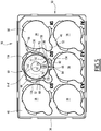
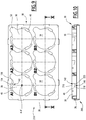
- a first culture set 10 according to the invention is represented on the Figures 1 to 3 .
- This set is intended to cultivate in vitro different types of cells and / or tissues or to maintain ex-vivo different tissues, with a view to their use for different tests or evaluations.
- the first set 10 includes, from bottom to top on the Figure 1 , a tray 12 for receiving a culture medium 14, a first device 16 of culture according to the invention, intended to be mounted on the tray 12, and a lid 18 for capping the tray 12 and the device 16, to ensure the sterility of the system.
- Gaseous exchanges between the interior of the tray 12 covered with its lid 18 are allowed through days. However, the days allowing these exchanges are of such size that they prevent bacterial contaminations.
- the tray 12 defines at least one cavity 20 for receiving the medium 14 and an upper surface 22 for mounting the device 16, extending along the upper edge of the tray 12.
- the cavity 20 opens upwards through the upper surface 22.
- the tray 12 has a single cavity 20 containing a common culture medium 14.
- the tray 12 defines a plurality of cavities 20, designated by the term "well”, sealed to each other to contain different media.
- the medium 14 is advantageously a liquid. It is able to impregnate the cells or tissues to be cultivated to promote their growth and keep them alive.
- the liquid is for example an aqueous solution of different nutrients such as mineral salts, reagents, vitamins ...
- the medium 14 can be solid. In this case, it is called "agar".
- the culture device 16 comprises a nacelle support 30 intended to be engaged above the tank 12, at least one nacelle 32 for culture to be carried by the nacelle support 30 and, according to the invention, means 34 for retaining releasable from each nacelle 32 on the support 30, which will be described in detail below.
- the support 30 comprises a substantially flat body 36 delimiting a plurality of openings 38 for receiving nacelles.
- the body 36 defines six receiving openings 38. More generally, the number of receiving openings 38 is advantageously equal to the number of nacelles 32 and is between 1 and 96.
- the body 36 extends between an upper surface 40 for retaining the nacelles 32 and a lower mounting surface 42 on the tank 12.
- the body 36 advantageously has a thickness, taken between the surfaces 40 and 42 less than its other dimensions.
- the body 36 has a contour of substantially complementary shape to the outer contour of the tray 12 along its upper edge.
- the outline is rectangular.
- the upper surface 40 is substantially horizontal when the body 36 is mounted on the tray 12.
- the upper surface 40 delimits, at the periphery of each receiving opening 38, a first nacelle retaining step 44 and a second retaining step 46. nacelle located opposite the first step 44.
- each step 44, 46 delimits a substantially horizontal bottom surface 48 situated slightly below the average level of the upper surface 40.
- Each receiving opening 38 extends along a vertical axis AA 'of insertion of the nacelle into the opening 38, between the lower surface 42 and the upper surface 40. Each receiving opening 38 is through, so that that it opens into the surfaces 40 and 42.
- Each opening 38 has a substantially constant horizontal section over its entire height through the body 36.
- each opening 38 comprises a central region 50 of outer section substantially similar to the outer section of a nacelle 32 and a peripheral notch 52 which extends outwardly the central region 50 radially with respect to the axis A-A '.
- the central region 50 is circular in outline.
- the peripheral indentation 52 opens into the central region 50. It extends angularly around the axis A-A 'in an angular sector with a range of less than 30 °.
- the notch 52 thus defines, when the nacelle 32 is inserted in the region 50, an access passage to the culture medium contained in the cavity 20.
- a sampling, filling or dosing tool such as a pipette, can therefore be introduced into the indentation 52 to feed culture medium or take or add any other substance in the culture medium, without having to move the pod 32.
- the support 30 is movable relative to the base tray 12 between a position engaged on the tray 12, wherein the support 14 substantially closes the or each cavity 20, with the exception of the passage openings 38, and a disassembled position at the gap of the tray 12 for the joint handling nacelles 32 retained in the support 30, as will be described in detail below.
- the upper retaining surface 40 is oriented upwards.
- each nacelle 32 comprises a hollow container 60, a culture substrate 62 mounted in the container 60, a support flange 64 on the retaining surface 40, in the form of a flange, and an arm 66 for supporting and manipulating the the nacelle 32.
- the container 60 comprises a substantially horizontal bottom wall 68 on the Figure 2 and a lateral peripheral wall 70 delimiting an interior culture volume 72 opening through an upper opening 73.
- the junction 73A between the bottom wall 68 and the lateral peripheral wall 70 is advantageously rounded in the interior volume 72, in order to ensure ideal flow of the various liquids that are likely to be deposited in the interior volume 72.
- the bottom wall 68 extends substantially perpendicular to the insertion axis A-A 'of the nacelle 32 in a receiving opening.
- the bottom wall 68 delimits a central passage 74 for feeding culture medium opening into the internal volume 72.
- the central passage 74 is of axis AA 'and of substantially circular shape.
- It has a variable surface depending on the culture substrate and generally greater than 10% of the area bounded by the bottom wall.
- the side wall 70 projects upwardly from the bottom wall 68 to an upper edge 75. It has a substantially cylindrical shape of axis A-A '. It delimits two lateral notches 76 of access to the inner volume 72 located on either side of a median vertical plane passing through the axis A-A '.
- the notches 76 open upwards around the upper opening 73.
- the height of the notches 76, taken parallel to the axis AA 'between the upper edge 75 and the bottom wall 68 is greater than the thickness of the body 36, taken along the axis AA 'in order to guarantee large gas exchanges between the different compartments of the device.
- the notches 76 allow easy access to the internal volume 72, especially for the sampling, using a gripping tool such as a clamp, of the sample grown in the volume 72.
- the side wall carries spacers protruding externally from the wall to prevent contact between the wall 70 and the body 36 in the receiving opening 38 and limit the rise of culture medium by capillarity.
- the culture substrate 62 is attached to the bottom wall 68 at the top or bottom around the passage 74. This substrate closes the passage 74.
- the substrate 62 is permeable to allow the entry of culture medium into the interior volume 72 to through passage 74. It defines an upper culture surface 78 for receiving the cells or tissues to be cultured. It is made for example based on a collagen sponge, or a collagen film or based on a polycarbonate matrix, or a synthetic fabric such as nylon or a metal grid.
- the substrate 62 is formed directly in the bottom wall 68 integrally with the bottom wall. It delimits a plurality of passage openings 74 for the diffusion of culture media in the volume 72.
- the substrate 62 is impervious and at least one feed passage 74 is provided away from the culture surface 78 in the bottom wall 68 or in a lower part of the side wall 70 situated in the vicinity from the bottom wall 68.
- the bearing flange 64 is integral with the container 60. It extends radially away from the axis AA 'perpendicular to this axis A-A'. It has a horizontal section, taken perpendicular to the axis A-A ', similar to the horizontal section defined by the first step 44.
- the flange 64 defines a first lower bearing surface 80 to be applied to the retaining surface 40 in the culture position.
- the arm 66 extends radially away from the axis AA 'opposite the flange 64. It comprises a substantially horizontal support plate 82 and a catch pin 84 which protrudes upwards from the tray 82.
- the plate 82 defines a second lower bearing surface 86 on the retaining surface 40, of horizontal section substantially similar to the horizontal section of the second step 46.
- the arm 66 has an angular extent, taken around the axis A-A ', less than the angular extent of the rim 64.
- Each nacelle 32 is movable relative to the support 30 between a culture position, represented on the Figure 3 , in which it is engaged in a receiving opening 38, and a handling position, represented on the Figure 1 , in which the nacelle 32 is disposed away from the support 30 to be freely movable relative to the support 30.
- the nacelle 32 In the culture position, the nacelle 32 has been inserted into a receiving opening 38, parallel to the axis A-A '.
- the first bearing surface 80 is applied against the surface of the first step 44 on the retaining surface 40.
- the second bearing surface 86 is applied against the surface of the second step 46 on the upper retaining surface 40.
- the bottom wall 68 projects downwardly beyond the lower surface 42 so as to be able to soak in the culture medium 14 when the support 30 is mounted on the tank 12.
- the grasping pin 84 protrudes above the upper retaining surface 40 to be easily grasped by a user of the device with the aid of his fingers or with the aid of a gripping tool such as a gripper. .
- the releasable retaining means 34 comprise a retaining member formed by a retaining projection 100 integral with the nacelle 32, and a complementary retaining member 102 for gripping the retaining projection 100, integral with the body 36 in the vicinity of each opening 38.
- the projection 100 is integral with the nacelle 32. It is formed by a vertical blade 104 extending radially with respect to the axis AA 'under the plate 82 and outside the side wall 70 in the vicinity of the upper edge 75.
- the blade 104 has a substantially constant thickness.
- a clasping member 102 is formed in the body 36 in the vicinity of each receiving opening 38.
- Each member 102 defines a groove 106 for receiving the projection, of slightly smaller width than that of the blade 104.
- the groove 106 extends radially outwardly from the receiving opening 38 with respect to the axis A-A '. It opens up into the bottom wall 48 of the second step 46.
- the projection 100 is inserted into force in the groove 106 defined by the squeezing member 102.
- the retaining means 34 cooperate to hold the nacelle 32 in the opening 38 when a joint reversal of the support 30 and the nacelle 32, wherein the bearing surface 40 is oriented downwards and wherein the bearing surfaces 80 and 86 are oriented upwards.
- the support 30 and the nacelle 32 are movable jointly regardless of the orientation of the retaining surface 40.
- the projection 100 is moved out of the groove 106, which allows the extraction of the nacelle 32 out of the receiving opening 38 substantially along the axis A-A '.
- the cover 18 is adapted to cover the device 16 and the tray 12 to define, inside the culture assembly 10, a culture space having a controlled and sterile atmosphere and containing the pods 32.
- the nacelle 32 In an auxiliary culture position, the nacelle 32 is just placed on the upper surface 40 of the body without engagement of the retaining means 34. The nacelle 32 is then not maintained in the receiving opening 38 during a joint reversal support 30 and the or each nacelle 32 which directs the retaining surface 40 downwards.
- each nacelle 32 is loaded with cells and / or tissue to be cultured.
- the cells and / or the tissue are deposited on the culture surface 78.
- the culture medium 14 is also introduced into the cavity 20.
- Each nacelle 32 is mounted in its culture position on the support 30.
- each hollow container 60 is introduced into a receiving opening 38 from the upper surface 40, until the first bearing surface 80 and the second bearing surface 86 is applied to the bottom surfaces 48 defined respectively on the first step 44 and on the second step 46 of the upper retaining surface 40.
- the projection 100 formed by the blade 104 enters force into the groove 106 defined by the clasp member 102, which immobilizes the nacelle 32 relative to the support 30 in the culture position.
- the culture device 16 is mounted on the tray 12. During the passage of the device 16 from the disassembled position to the mounted position, the bottom wall 68 of each nacelle 32 immerses in the culture medium 14 to soak the cells and / or the tissue through the feed passage 74 and the permeable substrate 62.
- the cover 18 is then closed to cover the device 16.
- the support 30 is mounted on the tray 12 before the arrangement of the nacelles 32 in the receiving openings 38.
- the support 30 and the nacelles 32 in their culture positions are moved together away from the tray 12.
- the presence of the means releasable retainer 34 optionally allows the support 30 to be turned to place the upper retaining surface 40 facing downwards, while maintaining the nacelles 32 integral with the support 30.
- the nacelles 32 are retained in the support 30, all of the bottom walls 68 and the substrates 62 are advantageously all maintained in the same plane.
- the arrangement of the pods 32 in the body 36 and the disposition of the body 36 relative to the tray 12 advantageously makes it possible to place the bottom walls 68 and the substrates 62 in the same horizontal plane, parallel to the plane on which the tray is disposed.
- each substrate 62 is then possible to arrange each substrate 62 at the same position called air-liquid interface or to perform a simultaneous heat treatment, for example freezing contact.
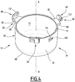
- a second assembly 130 according to the invention is partially represented on the Figures 4 to 6 .
- the nacelles 32 of the second set comprise three support arms 66 distributed at the periphery of the side wall 70.
- the side wall 70 is also devoid of notches 76 and has a substantially constant height about the axis A-A '.
- Each grasping pin 84 is formed by a hook 132 which protrudes vertically along the outer edge of the plate 82.
- the upper retaining surface 40 delimits three steps 134 distributed around the periphery of each receiving opening 38.
- Each step 134 has an angular extent, taken about the axis A-A ', greater than the angular extent around the AA axis of each arm 66.
- each step 134 defines two radial rotational locking edges 136 of the nacelle 32, as will be described below.
- the releasable retaining means 34 of the nacelle differ from the retaining means 34 of the first assembly 10 in that the retaining members and the complementary retaining members are respectively formed by integral stops 140.
- each stop 140 projects radially outwardly relative to the side wall 70 of the nacelle 32.
- Each stop 140 defines a substantially horizontal upper abutment surface 144.
- each complementary abutment 142 projects radially towards the axis AA 'in the receiving opening 38 from the body 36.
- Each complementary abutment 142 defines a substantially horizontal lower surface 146.
- the nacelle 32 When the bearing surfaces 86 are arranged in abutment on the upper retaining surface 40, the nacelle 32 is rotatably mounted about the axis AA 'in the receiving opening 38 between an insertion position of the nacelle 32 in the receiving opening 38 and the culture position.
- the abutment 140 and the complementary abutment 142 are located angularly apart from each other about the axis A-A '.
- the nacelle 32 In the locked culture position, the nacelle 32 has been pivoted about the axis AA 'to bring the lower abutment surface 146 axially and angularly facing the abutment upper surface 144.
- the complementary abutment 142 is situated just below the stop 140 and closes the space above this stop 140 parallel to the axis A-A '.
- the two stops 142, 144 are then in contact to prevent the extraction up of the nacelle 32 from the receiving opening 38.
- each support plate 82 cooperates with a locking edge 136 of a step to prevent the rotation of the nacelle about the axis AA 'in a first direction beyond the locked culture position. .
- each nacelle 32 When using the second set 130, each nacelle 32 is inserted into a retaining aperture 38 by moving it along the axis A-A 'to bring it into the insertion position. During this movement, each stop 140 passes successively above, laterally opposite, then below complementary stops 142.
- the nacelle 32 is pivoted about the axis A-A 'by sliding each arm 66 on a step 134 in the first direction until the plate 82 abuts laterally against a locking edge 136.
- each abutment 140 passes angularly opposite a complementary abutment 142.
- the cooperation between the upper surface 144 of the abutment 140 and the lower surface 146 of the complementary abutment 142 then blocks the nacelle 32 in its culture position. .
- the bottom wall 68 delimits a radial groove 150 for guiding liquid opening into the culture surface 78.
- the releasable retaining means 34 comprise means for screwing the nacelle 32 into the body 36.
- These screwing means comprise for example an external thread secured to the nacelle 32 and an internal thread secured to the body 36 disposed in the opening 38.
- the releasable retaining means 34 are formed by latching means.
- the assemblies according to the invention are made in SBS format to allow manipulation by a robot.
- releasable retaining means 34 comprising a bayonet mechanism has the advantage of avoiding mechanical wear over time of the arms.
- the lower surfaces 86 of the arms 66 are firmly applied to the retaining surfaces 40, which guarantees perfect flatness of the bottom wall 68 with respect to the culture tank 12.
- the immersion of the bottom wall 68 in the culture medium 14 is identical in all points of the bottom of the nacelle 32, which ensures that the contents of each nacelle 32 is placed precisely at the interface between the air and the liquid culture medium.
- each nacelle 32 remains stationary when a force is applied from bottom to top on the bottom wall 68, for example when the nacelles 32 are placed in the same plane to undergo a thermal shock.
- each stop 140 present on the nacelle 32 is retained by the complementary abutment 142 present on the support 30.
- the cooperation between the lower surface 86 of the arms 66 and the retaining surface 40 ensures that the nacelle 32 remains stationary when a thrust force directed from top to bottom is applied to the nacelle 32.
- a third culture assembly 210 according to the invention is partially represented on the Figures 7 to 10 .
- each nacelle 32 advantageously delimit a hollow cavity 212 own capture to receive a tool for manipulating the nacelle between its insertion position and its locked position.
- This tool is for example a tweezers with two or three branches.
- the cavities 212 open upwards and downwards parallel to the axis A-A '.
- the third assembly 210 has retaining means 34 of the bayonet type.
- each upper abutment surface 144 of a stop 140 opens out facing an arm 66, opposite the lower surface 86.
- each arm thus delimits with the upper surface 144 of the abutment 140 opposite, a passage 214 for insertion of the complementary abutment 142.
- the abutment 140 is formed in this example by an axial rib projecting from the side wall 70.
- the nacelle 32 of the third assembly 210 advantageously comprises a notch 76 in the side wall 70, formed between each pair of arms 66 adjacent.
- the height of the notches 76 is less than their maximum width. This height is advantageously less than 50% of the height of the side wall 70. This dimensional choice guarantees the exchanges between the interior of the nacelle 32 and the outside, whatever the position of the nacelle 32 between its position. insertion and its locked position of culture.
- the notches 76 are each in the general shape of inverted T.
- the support 30 of the third set 210 comprises, around each opening 38, a plurality of steps 134 each delimiting an upper surface 40 for retaining an arm 66.
- the complementary stops 142 protrude radially into the receiving opening 38 towards the axis A-A 'of the receiving opening 38.
- Each complementary abutment 142 has a horizontal upper surface 216 which is flush and extends radially towards the axis AA 'the upper retaining surface 40, and a lower surface 146 intended to cooperate with the abutment 140 carried by the nacelle 32.
- the lower surface 146 comprises a first portion 218 inclined relative to the horizontal, and a second substantially horizontal portion 220 for retaining the nacelle 32 in its locked culture position.
- the second portion 220 is angularly offset about the axis AA 'relative to the first portion 218.
- each nacelle 32 is first introduced into a retaining aperture 38 by moving it down along the axis A-A 'to bring it into the insertion position.
- the arms 66 are introduced into each step 134 at an angular distance from the complementary stop 142.
- the stop 140 passes successively above, laterally apart and then below the complementary stops 142.
- Each complementary abutment 142 is then located opposite the insertion passage 214 delimited between the lower surface 86 of each arm 66 and the upper surface 144 of the abutment 140.
- the nacelle 32 is pivoted about the axis A-A 'by sliding each arm 66 on a step 134, until the arm 66 abuts against a locking edge 136.
- the upper surface 144 of the abutment 140 enters successively in contact with the first inclined portion 218 of the complementary abutment 142, and is introduced between the lower surface 86 and the upper surface 144 in the insertion passage 214 , under the second part 220.
- the complementary abutment 142 is then clamped between the surfaces 86, 144 to axially lock along the axis A-A 'the nacelle 32 relative to the support in both directions along the axis A-A'.
- Clamping of the complementary stop is however adjusted to tolerate manual locking and unlocking.
Landscapes
- Health & Medical Sciences (AREA)
- Life Sciences & Earth Sciences (AREA)
- Engineering & Computer Science (AREA)
- Chemical & Material Sciences (AREA)
- Wood Science & Technology (AREA)
- Organic Chemistry (AREA)
- Bioinformatics & Cheminformatics (AREA)
- Zoology (AREA)
- Biomedical Technology (AREA)
- Genetics & Genomics (AREA)
- Sustainable Development (AREA)
- Microbiology (AREA)
- Biotechnology (AREA)
- Biochemistry (AREA)
- General Engineering & Computer Science (AREA)
- General Health & Medical Sciences (AREA)
- Immunology (AREA)
- Clinical Laboratory Science (AREA)
- Molecular Biology (AREA)
- Analytical Chemistry (AREA)
- Apparatus Associated With Microorganisms And Enzymes (AREA)
Claims (15)
- Zell- oder Gewebekultur-Vorrichtung (16) des Typs, der Folgendes umfasst:- einen Träger (30), der dazu bestimmt ist, einen Behälter (12), der ein Kulturmedium (14) enthält, wenigstens teilweise zu verschließen, wobei der Träger (30) einen Körper (36), der wenigstens eine Durchgangsöffnung (38) für die Aufnahme eines Schälchens begrenzt, und wenigstens eine Oberfläche (40) zum Halten des Schälchens, die dazu bestimmt ist, nach oben orientiert zu werden, wenn der Träger (30) den Behälter (12) verschließt, umfasst;- wenigstens ein Schälchen (32), das beweglich in Bezug auf den Träger (30) zwischen einer Kulturposition, in der das Schälchen (32) durch die Aufnahmeöffnung (38) hindurch in Eingriff ist, und einer Handhabungsposition, in der das Schälchen (32) in einem Abstand von dem Träger (30) angeordnet ist, montiert ist,wobei das Schälchen (32) eine Bodenwand (68), die eine Kulturoberfläche (78) trägt, und eine Seitenwand (70), die eine obere Öffnung (73) begrenzt, umfasst, wobei das Schälchen (32) wenigstens einen Durchlass (74) für die Versorgung der Kulturoberfläche (78) mit dem Kulturmedium, der von der oberen Öffnung (73) verschieden ist, begrenzt;
wobei die Vorrichtung (16) Mittel (34) zum freigebbaren Halten des oder jedes Schälchens (32) in seiner Kulturposition umfasst, wobei die freigebbaren Haltemittel (34) das oder jedes Schälchen (32) in der Aufnahmeöffnung (38) halten können, wenn der Träger (30) und das oder jedes Schälchen (32) gemeinsam gedreht werden, wodurch die Halteoberfläche (40) nach unten orientiert ist, wobei die Haltemittel (34) einen Mechanismus des Bajonetttyps bilden. - Vorrichtung (16) nach Anspruch 1, dadurch gekennzeichnet, dass in der Kulturposition wenigstens eine Abstützoberfläche (80, 86) des Schälchens (32) gegen die Halteoberfläche (40) gedrückt wird, wobei die freigebbaren Haltemittel (34) die Abstützoberfläche (80, 86) des Schälchens (32) gegen die Halteoberfläche (40) gedrückt halten können, wenn der Träger (30) und das oder jedes Schälchen (32) gemeinsam gedreht werden, wodurch die Halteoberfläche (34) nach unten orientiert wird.
- Vorrichtung (16) nach einem der vorhergehenden Ansprüche, dadurch gekennzeichnet, dass die freigebbaren Haltemittel (34) ein Halteorgan (100; 140), das mit einem Ersten des Schälchenträgers (30) und des Schälchens (32) fest verbunden ist, und ein komplementäres Halteorgan (102; 142), das mit einem Zweiten des Schälchenträgers (30) und des Schälchens (32) fest verbunden ist, um mit dem Halteorgan (100; 140) wenigstens bei der gemeinsamen Drehung des Trägers (30) und des oder jedes Schälchens (32) zusammenzuwirken, umfassen.
- Vorrichtung (16) nach Anspruch 3, dadurch gekennzeichnet, dass das Halteorgan (100) einen Vorsprung aufweist, wobei das komplementäre Halteorgan (102) wenigstens eine Kehle (106) zum Einklemmen des Vorsprungs begrenzt, deren Abmessung dafür ausgelegt ist, dass der Vorsprung in der Kehle (106) durch Einklemmen gehalten wird.
- Vorrichtung (16) nach Anspruch 3, dadurch gekennzeichnet, dass das Halteorgan einen Anschlag (140) umfasst, wobei das komplementäre Halteorgan einen komplementären Anschlag (142) umfasst, wobei das Schälchen (32) in der Aufnahmeöffnung (38) zwischen einer eingesetzten Position, in der der Raum, der sich über dem Anschlag (140) längs der Einsetzachse (A-A') des Schälchens (32) in die Aufnahmeöffnung (32) befindet, freigegeben ist, und der Kulturposition, in der der komplementäre Anschlag (142) in dem Raum angeordnet ist, der sich über dem Anschlag (140) längs einer Achse (A-A') des Einsetzens des Schälchens (32) in die Aufnahmeöffnung (38) befindet, verlagerbar ist.
- Vorrichtung (16) nach Anspruch 5, dadurch gekennzeichnet, dass das Schälchen (32) drehbar um die Einsetzachse (A-A') zwischen der Einsetzposition und der Kulturposition montiert ist, wobei die freigebbaren Haltemittel (34) vorteilhaft eine Oberfläche (136) für die Blockierung der Drehung des Schälchens (32) in seiner verriegelten Kulturposition umfassen.
- Vorrichtung (16) nach einem der Ansprüche 3 bis 6, dadurch gekennzeichnet, dass das Schälchen (32) wenigstens einen Arm (66) aufweist, der in Bezug auf die Seitenwand (70) transversal nach außen vorsteht, wobei der Arm (66) entweder das Halteorgan (100) oder das komplementäre Halteorgan (102) trägt.
- Vorrichtung nach einem der vorhergehenden Ansprüche, dadurch gekennzeichnet, dass in der Kulturposition das Schälchen (32) axial längs der Einsetzachse (A-A') unbeweglich ist.
- Vorrichtung (16) nach einem der vorhergehenden Ansprüche, dadurch gekennzeichnet, dass die Seitenwand (70) wenigstens eine Kerbe (76) begrenzt, die nach oben mündet, wobei sich die Kerbe (76) axial zu einer Höhe erstreckt, die höher als die Dicke des Körpers (34) ist.
- Vorrichtung (16) nach einem der vorhergehenden Ansprüche, dadurch gekennzeichnet, dass die Bodenwand (68) eine Kehle (150) für die Führung einer Flüssigkeit begrenzt, die sich radial zu der Kulturoberfläche (72) erstreckt.
- Vorrichtung (16) nach einem der vorhergehenden Ansprüche, dadurch gekennzeichnet, dass das Schälchen (32) ein Greiforgan (84) aufweist, das in einem Abstand von dem und über den Träger (30) vorsteht, wenn das Schälchen (32) seine Kulturposition einnimmt.
- Vorrichtung (16) nach einem der vorhergehenden Ansprüche, dadurch gekennzeichnet, dass die oder jede Aufnahmeöffnung (38) einen mittleren Bereich (50) aufweist, der das Schälchen (32) in seiner Kulturposition aufnehmen kann, und einen Umfangseinschnitt (52) aufweist, der sich radial in einem Abstand von dem mittleren Bereich (50) erstreckt, um das Einführen eines Werkzeugs in den Behälter (12) durch den Träger (30) zu ermöglichen, wenn das Schälchen (32) in dem mittleren Bereich (50) aufgenommen ist.
- Anordnung (10; 130) einer Zell- oder Gewebekultur, dadurch gekennzeichnet, dass sie Folgendes umfasst:- einen Behälter (12), der wenigstens einen Hohlraum (20) aufweist, der dazu bestimmt ist, ein Kulturmedium (14) aufzunehmen;- eine Vorrichtung (16) nach einem der vorhergehenden Ansprüche, wobei der Träger (30) an dem Behälter (12) montiert ist, um den Hohlraum (20) teilweise zu verschließen.
- Anordnung (10; 130) nach Anspruch 13, dadurch gekennzeichnet, dass der Träger (30) an dem Behälter (12) in der Weise montiert ist, dass eine Kulturoberfläche einer Bodenwand (68) eines Schälchens (32) horizontal angeordnet ist.
- Anordnung (10; 130) nach einem der Ansprüche 13 oder 14, dadurch gekennzeichnet, dass sie einen Deckel (18) umfasst, der den Träger (30) bedecken kann, wobei der Träger (30) und das oder jedes Schälchen (32) zwischen dem Behälter (12) und dem Deckel (18) in derselben Ebene steril aufgenommen sind.
Applications Claiming Priority (2)
| Application Number | Priority Date | Filing Date | Title |
|---|---|---|---|
| FR0951062A FR2942239B1 (fr) | 2009-02-18 | 2009-02-18 | Dispositif de culture cellulaire ou tissulaire et ensemble associe |
| US16630309P | 2009-04-03 | 2009-04-03 |
Publications (2)
| Publication Number | Publication Date |
|---|---|
| EP2233560A1 EP2233560A1 (de) | 2010-09-29 |
| EP2233560B1 true EP2233560B1 (de) | 2019-04-03 |
Family
ID=41128032
Family Applications (1)
| Application Number | Title | Priority Date | Filing Date |
|---|---|---|---|
| EP10305161.1A Active EP2233560B1 (de) | 2009-02-18 | 2010-02-17 | Vorrichtung zur Zell- oder Gewebekultur und entsprechende Anordnung |
Country Status (4)
| Country | Link |
|---|---|
| EP (1) | EP2233560B1 (de) |
| ES (1) | ES2733345T3 (de) |
| FR (1) | FR2942239B1 (de) |
| PT (1) | PT2233560T (de) |
Families Citing this family (8)
| Publication number | Priority date | Publication date | Assignee | Title |
|---|---|---|---|---|
| CN102952751A (zh) * | 2011-08-23 | 2013-03-06 | 首都医科大学附属北京友谊医院 | 多种细胞共培养支架 |
| CN105548529A (zh) * | 2016-01-16 | 2016-05-04 | 刘静 | 一种细胞分泌物专用测试装置 |
| DE202017003978U1 (de) | 2016-08-18 | 2017-08-28 | Brand Gmbh + Co Kg | Zellkultureinsatz und Vorrichtung zum Kultivieren von Zellen |
| FR3067040B1 (fr) | 2017-06-02 | 2021-06-11 | Oreal | Dispositif destine a recevoir un depot de materiau par impression, ensemble et procede associes |
| WO2020212134A1 (en) * | 2019-04-16 | 2020-10-22 | Cellink Ab | A structure useful for 3d bioprinting |
| CN110804549B (zh) * | 2019-11-20 | 2022-08-23 | 山东中医药大学附属医院 | 一种低压低氧细胞实验装置 |
| GB2610208A (en) * | 2021-08-26 | 2023-03-01 | Newcells Biotech Ltd | Fluid flow plate |
| DE102021132560A1 (de) * | 2021-12-09 | 2023-06-15 | Sabeu Gmbh & Co. Kg | Probenvorrichtung für Zellkulturen |
Citations (1)
| Publication number | Priority date | Publication date | Assignee | Title |
|---|---|---|---|---|
| US20010036426A1 (en) * | 2000-03-09 | 2001-11-01 | Gunter Kohrmann | Arrangement for the contamination-free processing of reaciton sequences, in particular molecular-biological reaction sequences, closure carrier and individual closure elements for such an arrangement, and storage and dispensing arrangement for individual closure elements |
Family Cites Families (6)
| Publication number | Priority date | Publication date | Assignee | Title |
|---|---|---|---|---|
| CA2055966C (en) * | 1990-12-19 | 1995-08-01 | Oresta Natalia Fedun | Cell culture insert |
| GB9311276D0 (en) * | 1993-06-01 | 1993-07-21 | Whatman Scient Limited | Well inserts for use in tissue culture |
| US5514343A (en) * | 1994-06-22 | 1996-05-07 | Nunc, As | Microtitration system |
| US5801055A (en) * | 1997-09-10 | 1998-09-01 | Becton Dickinson And Company | Multi-well culture dish assembly |
| DE10240787B4 (de) * | 2002-08-30 | 2004-07-22 | Oxyphen Ag | Zellkultureinsatz |
| EP1893738B1 (de) * | 2005-06-10 | 2018-12-05 | Nunc A/S | Kultureinsatzträger, kultureinsatz und kultureinsatzsystem |
-
2009
- 2009-02-18 FR FR0951062A patent/FR2942239B1/fr not_active Expired - Fee Related
-
2010
- 2010-02-17 ES ES10305161T patent/ES2733345T3/es active Active
- 2010-02-17 EP EP10305161.1A patent/EP2233560B1/de active Active
- 2010-02-17 PT PT10305161T patent/PT2233560T/pt unknown
Patent Citations (1)
| Publication number | Priority date | Publication date | Assignee | Title |
|---|---|---|---|---|
| US20010036426A1 (en) * | 2000-03-09 | 2001-11-01 | Gunter Kohrmann | Arrangement for the contamination-free processing of reaciton sequences, in particular molecular-biological reaction sequences, closure carrier and individual closure elements for such an arrangement, and storage and dispensing arrangement for individual closure elements |
Also Published As
| Publication number | Publication date |
|---|---|
| FR2942239B1 (fr) | 2013-07-26 |
| FR2942239A1 (fr) | 2010-08-20 |
| ES2733345T3 (es) | 2019-11-28 |
| EP2233560A1 (de) | 2010-09-29 |
| PT2233560T (pt) | 2019-07-11 |
Similar Documents
| Publication | Publication Date | Title |
|---|---|---|
| EP2233560B1 (de) | Vorrichtung zur Zell- oder Gewebekultur und entsprechende Anordnung | |
| EP3331637B1 (de) | Mischbehälter und verfahren zum aufbau eines mischbehälters mit einem teleskopischen welle | |
| CA2176324A1 (fr) | Procede d'identification bacterienne et de determination de la sensibilite de bacteries a des antibiotiques et appareil et supports de mesure pour la mise en oeuvre de ce procede | |
| EP2230296B1 (de) | Vorrichtung zur Zell- oder Gewebekultur mit Adapter und entsprechende Anordnung zur Zell- oder Gewebekultur | |
| FR2881434A1 (fr) | Dispositif de support de culture de cellules | |
| FR2754474A1 (fr) | Dispositif pour le depot d'un produit visqueux ou pateux sur un substrat a travers les ouvertures d'un pochoir | |
| EP2027246B1 (de) | Vorrichtung zur kultivierung von zellen oder mikroorganismen | |
| BE1004610A5 (fr) | Bioreacteur rotatif a grande surface pour culture de cellules adherentes ou en suspension. | |
| WO2021250360A1 (fr) | Dispositif de support de tubes utilisés pour l'analyse d'échantillons par des techniques d'amplification d'acides nucléiques et procédé d'utilisation d'un tel dispositif | |
| FR2882943A1 (fr) | Appareil de traitement d'echantillons biologiques. | |
| FR3067040A1 (fr) | Dispositif destine a recevoir un depot de materiau par impression, ensemble et procede associes | |
| EP1893123B1 (de) | Verfahren zur verpackung einer vorbestimmten dosis einer flüssigen substanz in einem strohhalm und vorrichtung zur durchführung dieses verfahrens | |
| FR2915488A1 (fr) | Appareil et procedes d'etalement a l'interieur de receptacles, de toutes solutions contenant un echantillon. | |
| EP0742284B1 (de) | Verfahren zur Identifizierung von Bakterien und zur Bestimmung von deren Empfindlichkeit gegen Antibiotika sowie Vorrichtung und Messträger dafür | |
| WO2002057405A1 (fr) | Boite sterile pour la culture de micro-organismes, ensemble et distributeur de boites | |
| WO2015192913A1 (fr) | Dispositif de prélèvement simultané et de transfert de multiples échantillons | |
| EP4016046B1 (de) | Vorrichtung zur gravimetrischen verdünnung einer probe mit einer vorbestimmten flüssigkeitsmenge und entsprechendes verfahren | |
| CN210223976U (zh) | 一种用于半导体制程工艺的托盘机构 | |
| EP3732283B1 (de) | Vorrichtung zur kultivierung von mikroorganismen | |
| WO2024133447A1 (fr) | Dispositif clos de culture et de transport de produit de therapie cellulaire | |
| OA22225A (fr) | Dispositif clos de culture et de transport de produit de thérapie cellulaire. | |
| FR3104561A1 (fr) | Dispositif de stockage et de distribution de bandelettes | |
| FR2698375A1 (fr) | Dispositif pour le transport et le stockage de liquides utilisable, notamment, pour réaliser des kits pour test in vitro. | |
| FR2833608A1 (fr) | Dispositif sterile comportant une membrane filtrante pour la culture de micro-organismes | |
| FR3103495A1 (fr) | Boite de Pétri |
Legal Events
| Date | Code | Title | Description |
|---|---|---|---|
| PUAI | Public reference made under article 153(3) epc to a published international application that has entered the european phase |
Free format text: ORIGINAL CODE: 0009012 |
|
| AK | Designated contracting states |
Kind code of ref document: A1 Designated state(s): AT BE BG CH CY CZ DE DK EE ES FI FR GB GR HR HU IE IS IT LI LT LU LV MC MK MT NL NO PL PT RO SE SI SK SM TR |
|
| AX | Request for extension of the european patent |
Extension state: AL BA RS |
|
| 17P | Request for examination filed |
Effective date: 20101008 |
|
| 17Q | First examination report despatched |
Effective date: 20160421 |
|
| REG | Reference to a national code |
Ref country code: DE Ref legal event code: R079 Ref document number: 602010057966 Country of ref document: DE Free format text: PREVIOUS MAIN CLASS: C12M0001120000 Ipc: C12M0001340000 |
|
| GRAP | Despatch of communication of intention to grant a patent |
Free format text: ORIGINAL CODE: EPIDOSNIGR1 |
|
| STAA | Information on the status of an ep patent application or granted ep patent |
Free format text: STATUS: GRANT OF PATENT IS INTENDED |
|
| RIC1 | Information provided on ipc code assigned before grant |
Ipc: C12M 1/34 20060101AFI20181026BHEP |
|
| INTG | Intention to grant announced |
Effective date: 20181120 |
|
| GRAS | Grant fee paid |
Free format text: ORIGINAL CODE: EPIDOSNIGR3 |
|
| GRAA | (expected) grant |
Free format text: ORIGINAL CODE: 0009210 |
|
| STAA | Information on the status of an ep patent application or granted ep patent |
Free format text: STATUS: THE PATENT HAS BEEN GRANTED |
|
| AK | Designated contracting states |
Kind code of ref document: B1 Designated state(s): AT BE BG CH CY CZ DE DK EE ES FI FR GB GR HR HU IE IS IT LI LT LU LV MC MK MT NL NO PL PT RO SE SI SK SM TR |
|
| REG | Reference to a national code |
Ref country code: GB Ref legal event code: FG4D Free format text: NOT ENGLISH |
|
| REG | Reference to a national code |
Ref country code: CH Ref legal event code: EP Ref country code: AT Ref legal event code: REF Ref document number: 1115740 Country of ref document: AT Kind code of ref document: T Effective date: 20190415 |
|
| REG | Reference to a national code |
Ref country code: DE Ref legal event code: R096 Ref document number: 602010057966 Country of ref document: DE |
|
| REG | Reference to a national code |
Ref country code: IE Ref legal event code: FG4D Free format text: LANGUAGE OF EP DOCUMENT: FRENCH |
|
| REG | Reference to a national code |
Ref country code: CH Ref legal event code: NV Representative=s name: MICHELI AND CIE SA, CH |
|
| REG | Reference to a national code |
Ref country code: PT Ref legal event code: SC4A Ref document number: 2233560 Country of ref document: PT Date of ref document: 20190711 Kind code of ref document: T Free format text: AVAILABILITY OF NATIONAL TRANSLATION Effective date: 20190701 |
|
| REG | Reference to a national code |
Ref country code: NL Ref legal event code: FP |
|
| REG | Reference to a national code |
Ref country code: LT Ref legal event code: MG4D |
|
| REG | Reference to a national code |
Ref country code: AT Ref legal event code: MK05 Ref document number: 1115740 Country of ref document: AT Kind code of ref document: T Effective date: 20190403 |
|
| PG25 | Lapsed in a contracting state [announced via postgrant information from national office to epo] |
Ref country code: NO Free format text: LAPSE BECAUSE OF FAILURE TO SUBMIT A TRANSLATION OF THE DESCRIPTION OR TO PAY THE FEE WITHIN THE PRESCRIBED TIME-LIMIT Effective date: 20190703 Ref country code: LT Free format text: LAPSE BECAUSE OF FAILURE TO SUBMIT A TRANSLATION OF THE DESCRIPTION OR TO PAY THE FEE WITHIN THE PRESCRIBED TIME-LIMIT Effective date: 20190403 Ref country code: HR Free format text: LAPSE BECAUSE OF FAILURE TO SUBMIT A TRANSLATION OF THE DESCRIPTION OR TO PAY THE FEE WITHIN THE PRESCRIBED TIME-LIMIT Effective date: 20190403 Ref country code: CZ Free format text: LAPSE BECAUSE OF FAILURE TO SUBMIT A TRANSLATION OF THE DESCRIPTION OR TO PAY THE FEE WITHIN THE PRESCRIBED TIME-LIMIT Effective date: 20190403 Ref country code: SE Free format text: LAPSE BECAUSE OF FAILURE TO SUBMIT A TRANSLATION OF THE DESCRIPTION OR TO PAY THE FEE WITHIN THE PRESCRIBED TIME-LIMIT Effective date: 20190403 Ref country code: FI Free format text: LAPSE BECAUSE OF FAILURE TO SUBMIT A TRANSLATION OF THE DESCRIPTION OR TO PAY THE FEE WITHIN THE PRESCRIBED TIME-LIMIT Effective date: 20190403 |
|
| REG | Reference to a national code |
Ref country code: ES Ref legal event code: FG2A Ref document number: 2733345 Country of ref document: ES Kind code of ref document: T3 Effective date: 20191128 |
|
| PG25 | Lapsed in a contracting state [announced via postgrant information from national office to epo] |
Ref country code: LV Free format text: LAPSE BECAUSE OF FAILURE TO SUBMIT A TRANSLATION OF THE DESCRIPTION OR TO PAY THE FEE WITHIN THE PRESCRIBED TIME-LIMIT Effective date: 20190403 Ref country code: GR Free format text: LAPSE BECAUSE OF FAILURE TO SUBMIT A TRANSLATION OF THE DESCRIPTION OR TO PAY THE FEE WITHIN THE PRESCRIBED TIME-LIMIT Effective date: 20190704 Ref country code: PL Free format text: LAPSE BECAUSE OF FAILURE TO SUBMIT A TRANSLATION OF THE DESCRIPTION OR TO PAY THE FEE WITHIN THE PRESCRIBED TIME-LIMIT Effective date: 20190403 Ref country code: BG Free format text: LAPSE BECAUSE OF FAILURE TO SUBMIT A TRANSLATION OF THE DESCRIPTION OR TO PAY THE FEE WITHIN THE PRESCRIBED TIME-LIMIT Effective date: 20190703 |
|
| PG25 | Lapsed in a contracting state [announced via postgrant information from national office to epo] |
Ref country code: AT Free format text: LAPSE BECAUSE OF FAILURE TO SUBMIT A TRANSLATION OF THE DESCRIPTION OR TO PAY THE FEE WITHIN THE PRESCRIBED TIME-LIMIT Effective date: 20190403 Ref country code: IS Free format text: LAPSE BECAUSE OF FAILURE TO SUBMIT A TRANSLATION OF THE DESCRIPTION OR TO PAY THE FEE WITHIN THE PRESCRIBED TIME-LIMIT Effective date: 20190803 |
|
| REG | Reference to a national code |
Ref country code: DE Ref legal event code: R097 Ref document number: 602010057966 Country of ref document: DE |
|
| PG25 | Lapsed in a contracting state [announced via postgrant information from national office to epo] |
Ref country code: RO Free format text: LAPSE BECAUSE OF FAILURE TO SUBMIT A TRANSLATION OF THE DESCRIPTION OR TO PAY THE FEE WITHIN THE PRESCRIBED TIME-LIMIT Effective date: 20190403 Ref country code: SK Free format text: LAPSE BECAUSE OF FAILURE TO SUBMIT A TRANSLATION OF THE DESCRIPTION OR TO PAY THE FEE WITHIN THE PRESCRIBED TIME-LIMIT Effective date: 20190403 Ref country code: DK Free format text: LAPSE BECAUSE OF FAILURE TO SUBMIT A TRANSLATION OF THE DESCRIPTION OR TO PAY THE FEE WITHIN THE PRESCRIBED TIME-LIMIT Effective date: 20190403 Ref country code: EE Free format text: LAPSE BECAUSE OF FAILURE TO SUBMIT A TRANSLATION OF THE DESCRIPTION OR TO PAY THE FEE WITHIN THE PRESCRIBED TIME-LIMIT Effective date: 20190403 |
|
| PLBE | No opposition filed within time limit |
Free format text: ORIGINAL CODE: 0009261 |
|
| STAA | Information on the status of an ep patent application or granted ep patent |
Free format text: STATUS: NO OPPOSITION FILED WITHIN TIME LIMIT |
|
| PG25 | Lapsed in a contracting state [announced via postgrant information from national office to epo] |
Ref country code: SM Free format text: LAPSE BECAUSE OF FAILURE TO SUBMIT A TRANSLATION OF THE DESCRIPTION OR TO PAY THE FEE WITHIN THE PRESCRIBED TIME-LIMIT Effective date: 20190403 |
|
| 26N | No opposition filed |
Effective date: 20200106 |
|
| PG25 | Lapsed in a contracting state [announced via postgrant information from national office to epo] |
Ref country code: TR Free format text: LAPSE BECAUSE OF FAILURE TO SUBMIT A TRANSLATION OF THE DESCRIPTION OR TO PAY THE FEE WITHIN THE PRESCRIBED TIME-LIMIT Effective date: 20190403 |
|
| PG25 | Lapsed in a contracting state [announced via postgrant information from national office to epo] |
Ref country code: SI Free format text: LAPSE BECAUSE OF FAILURE TO SUBMIT A TRANSLATION OF THE DESCRIPTION OR TO PAY THE FEE WITHIN THE PRESCRIBED TIME-LIMIT Effective date: 20190403 |
|
| PG25 | Lapsed in a contracting state [announced via postgrant information from national office to epo] |
Ref country code: MC Free format text: LAPSE BECAUSE OF FAILURE TO SUBMIT A TRANSLATION OF THE DESCRIPTION OR TO PAY THE FEE WITHIN THE PRESCRIBED TIME-LIMIT Effective date: 20190403 |
|
| PG25 | Lapsed in a contracting state [announced via postgrant information from national office to epo] |
Ref country code: IE Free format text: LAPSE BECAUSE OF NON-PAYMENT OF DUE FEES Effective date: 20200217 |
|
| PG25 | Lapsed in a contracting state [announced via postgrant information from national office to epo] |
Ref country code: MT Free format text: LAPSE BECAUSE OF FAILURE TO SUBMIT A TRANSLATION OF THE DESCRIPTION OR TO PAY THE FEE WITHIN THE PRESCRIBED TIME-LIMIT Effective date: 20190403 Ref country code: CY Free format text: LAPSE BECAUSE OF FAILURE TO SUBMIT A TRANSLATION OF THE DESCRIPTION OR TO PAY THE FEE WITHIN THE PRESCRIBED TIME-LIMIT Effective date: 20190403 |
|
| PG25 | Lapsed in a contracting state [announced via postgrant information from national office to epo] |
Ref country code: MK Free format text: LAPSE BECAUSE OF FAILURE TO SUBMIT A TRANSLATION OF THE DESCRIPTION OR TO PAY THE FEE WITHIN THE PRESCRIBED TIME-LIMIT Effective date: 20190403 |
|
| PGFP | Annual fee paid to national office [announced via postgrant information from national office to epo] |
Ref country code: NL Payment date: 20251215 Year of fee payment: 17 Ref country code: FR Payment date: 20251208 Year of fee payment: 17 |
|
| REG | Reference to a national code |
Ref country code: CH Ref legal event code: U11 Free format text: ST27 STATUS EVENT CODE: U-0-0-U10-U11 (AS PROVIDED BY THE NATIONAL OFFICE) Effective date: 20260301 |
|
| PGFP | Annual fee paid to national office [announced via postgrant information from national office to epo] |
Ref country code: LU Payment date: 20260216 Year of fee payment: 17 |
|
| PGFP | Annual fee paid to national office [announced via postgrant information from national office to epo] |
Ref country code: GB Payment date: 20260106 Year of fee payment: 17 |
|
| PGFP | Annual fee paid to national office [announced via postgrant information from national office to epo] |
Ref country code: ES Payment date: 20260305 Year of fee payment: 17 |
|
| PGFP | Annual fee paid to national office [announced via postgrant information from national office to epo] |
Ref country code: DE Payment date: 20251224 Year of fee payment: 17 |
|
| PGFP | Annual fee paid to national office [announced via postgrant information from national office to epo] |
Ref country code: BE Payment date: 20260105 Year of fee payment: 17 Ref country code: IT Payment date: 20260122 Year of fee payment: 17 |
|
| PGFP | Annual fee paid to national office [announced via postgrant information from national office to epo] |
Ref country code: PT Payment date: 20260216 Year of fee payment: 17 Ref country code: CH Payment date: 20260301 Year of fee payment: 17 |