EP2233735A2 - Pale d'éolienne comportant un volet de bord de fuite et un actionneur piézoélectrique - Google Patents
Pale d'éolienne comportant un volet de bord de fuite et un actionneur piézoélectrique Download PDFInfo
- Publication number
- EP2233735A2 EP2233735A2 EP10157166A EP10157166A EP2233735A2 EP 2233735 A2 EP2233735 A2 EP 2233735A2 EP 10157166 A EP10157166 A EP 10157166A EP 10157166 A EP10157166 A EP 10157166A EP 2233735 A2 EP2233735 A2 EP 2233735A2
- Authority
- EP
- European Patent Office
- Prior art keywords
- wind turbine
- trailing edge
- piezoelectric elements
- actuator structure
- edge section
- Prior art date
- Legal status (The legal status is an assumption and is not a legal conclusion. Google has not performed a legal analysis and makes no representation as to the accuracy of the status listed.)
- Withdrawn
Links
Images


Classifications
-
- F—MECHANICAL ENGINEERING; LIGHTING; HEATING; WEAPONS; BLASTING
- F03—MACHINES OR ENGINES FOR LIQUIDS; WIND, SPRING, OR WEIGHT MOTORS; PRODUCING MECHANICAL POWER OR A REACTIVE PROPULSIVE THRUST, NOT OTHERWISE PROVIDED FOR
- F03D—WIND MOTORS
- F03D7/00—Controlling wind motors
- F03D7/02—Controlling wind motors the wind motors having rotation axis substantially parallel to the air flow entering the rotor
- F03D7/022—Adjusting aerodynamic properties of the blades
- F03D7/0232—Adjusting aerodynamic properties of the blades with flaps or slats
-
- F—MECHANICAL ENGINEERING; LIGHTING; HEATING; WEAPONS; BLASTING
- F03—MACHINES OR ENGINES FOR LIQUIDS; WIND, SPRING, OR WEIGHT MOTORS; PRODUCING MECHANICAL POWER OR A REACTIVE PROPULSIVE THRUST, NOT OTHERWISE PROVIDED FOR
- F03D—WIND MOTORS
- F03D1/00—Wind motors with rotation axis substantially parallel to the air flow entering the rotor
- F03D1/06—Rotors
- F03D1/065—Rotors characterised by their construction elements
- F03D1/0675—Rotors characterised by their construction elements of the blades
-
- F—MECHANICAL ENGINEERING; LIGHTING; HEATING; WEAPONS; BLASTING
- F05—INDEXING SCHEMES RELATING TO ENGINES OR PUMPS IN VARIOUS SUBCLASSES OF CLASSES F01-F04
- F05B—INDEXING SCHEME RELATING TO WIND, SPRING, WEIGHT, INERTIA OR LIKE MOTORS, TO MACHINES OR ENGINES FOR LIQUIDS COVERED BY SUBCLASSES F03B, F03D AND F03G
- F05B2240/00—Components
- F05B2240/20—Rotors
- F05B2240/30—Characteristics of rotor blades, i.e. of any element transforming dynamic fluid energy to or from rotational energy and being attached to a rotor
- F05B2240/305—Flaps, slats or spoilers
- F05B2240/3052—Flaps, slats or spoilers adjustable
-
- F—MECHANICAL ENGINEERING; LIGHTING; HEATING; WEAPONS; BLASTING
- F05—INDEXING SCHEMES RELATING TO ENGINES OR PUMPS IN VARIOUS SUBCLASSES OF CLASSES F01-F04
- F05B—INDEXING SCHEME RELATING TO WIND, SPRING, WEIGHT, INERTIA OR LIKE MOTORS, TO MACHINES OR ENGINES FOR LIQUIDS COVERED BY SUBCLASSES F03B, F03D AND F03G
- F05B2240/00—Components
- F05B2240/20—Rotors
- F05B2240/30—Characteristics of rotor blades, i.e. of any element transforming dynamic fluid energy to or from rotational energy and being attached to a rotor
- F05B2240/31—Characteristics of rotor blades, i.e. of any element transforming dynamic fluid energy to or from rotational energy and being attached to a rotor of changeable form or shape
-
- F—MECHANICAL ENGINEERING; LIGHTING; HEATING; WEAPONS; BLASTING
- F05—INDEXING SCHEMES RELATING TO ENGINES OR PUMPS IN VARIOUS SUBCLASSES OF CLASSES F01-F04
- F05B—INDEXING SCHEME RELATING TO WIND, SPRING, WEIGHT, INERTIA OR LIKE MOTORS, TO MACHINES OR ENGINES FOR LIQUIDS COVERED BY SUBCLASSES F03B, F03D AND F03G
- F05B2260/00—Function
- F05B2260/40—Transmission of power
- F05B2260/407—Transmission of power through piezoelectric conversion
-
- F—MECHANICAL ENGINEERING; LIGHTING; HEATING; WEAPONS; BLASTING
- F05—INDEXING SCHEMES RELATING TO ENGINES OR PUMPS IN VARIOUS SUBCLASSES OF CLASSES F01-F04
- F05B—INDEXING SCHEME RELATING TO WIND, SPRING, WEIGHT, INERTIA OR LIKE MOTORS, TO MACHINES OR ENGINES FOR LIQUIDS COVERED BY SUBCLASSES F03B, F03D AND F03G
- F05B2260/00—Function
- F05B2260/70—Adjusting of angle of incidence or attack of rotating blades
- F05B2260/74—Adjusting of angle of incidence or attack of rotating blades by turning around an axis perpendicular the rotor centre line
-
- F—MECHANICAL ENGINEERING; LIGHTING; HEATING; WEAPONS; BLASTING
- F05—INDEXING SCHEMES RELATING TO ENGINES OR PUMPS IN VARIOUS SUBCLASSES OF CLASSES F01-F04
- F05B—INDEXING SCHEME RELATING TO WIND, SPRING, WEIGHT, INERTIA OR LIKE MOTORS, TO MACHINES OR ENGINES FOR LIQUIDS COVERED BY SUBCLASSES F03B, F03D AND F03G
- F05B2260/00—Function
- F05B2260/70—Adjusting of angle of incidence or attack of rotating blades
- F05B2260/79—Bearing, support or actuation arrangements therefor
-
- Y—GENERAL TAGGING OF NEW TECHNOLOGICAL DEVELOPMENTS; GENERAL TAGGING OF CROSS-SECTIONAL TECHNOLOGIES SPANNING OVER SEVERAL SECTIONS OF THE IPC; TECHNICAL SUBJECTS COVERED BY FORMER USPC CROSS-REFERENCE ART COLLECTIONS [XRACs] AND DIGESTS
- Y02—TECHNOLOGIES OR APPLICATIONS FOR MITIGATION OR ADAPTATION AGAINST CLIMATE CHANGE
- Y02E—REDUCTION OF GREENHOUSE GAS [GHG] EMISSIONS, RELATED TO ENERGY GENERATION, TRANSMISSION OR DISTRIBUTION
- Y02E10/00—Energy generation through renewable energy sources
- Y02E10/70—Wind energy
- Y02E10/72—Wind turbines with rotation axis in wind direction
Definitions
- the present invention relates to wind turbine blades, notably wind turbine blades with displaceable trailing edge sections, also referred to as flaps, useful for altering the aerodynamic profile of the blade and thereby influencing the lift and drag forces on the overall blade structure.
- the invention relates to an actuator structure for causing the trailing edge section of a blade to move relative to a main blade portion, the actuator structure comprising a stack of piezoelectric elements.
- Trailing edge flaps are known to influence the aerodynamic characteristics of wind turbine blades.
- WO 2004/088130 (Forskningscenter Ris ⁇ , Bak et al. ) discloses a wind turbine blade comprising one or more shape deformable trailing edge airfoil sections comprising actuator means for providing shape changes in the shape deformable trailing airfoil sections.
- WO 2004/088130 discloses the use of 'smart materials' and mechanical actuators integrated in a deformable materiel changing the outer geometry in the leading and trailing edge region and thereby changing the blade section aerodynamic forces. Such 'smart materials' are said to deform once a voltage is applied to them.
- Preferred materials are said to include: shape memory alloys, piezoelectric materials, magnetostrictive materials, electrorheological fluids, electrochromic materials, electroactive polymers, chiral materials, conducting polymers, photoactive materials, thick and thin films, optical fibres, tunable dielectrics, self monitoring materials, self assembly materials, self repairing/healing materials, biomaterials, power supplies, power sources, and self powering, multilayer and composite materials and/or 'smart composites'.
- the present invention provides a wind turbine blade comprising a main blade body and trailing edge section movably connected to the main blade body, the blade further comprising:
- the actuator structure may be controllable by voltage applied, e.g. via electrodes, to the stack of piezoelectric elements. It has been found that the use of a stack of piezoelectric elements renders the actuator structure reliable, stable and fatigue resistant. Moreover, it is easily controllable, e.g. in response to an applied voltage.
- the control of the actuating structure may conveniently be achieved by means of a control system, which applies voltage to the piezoelectric elements, for example in response to changes in the aerodynamic loads on the blade, absolute or relative wind velocity, turbulence, rotor rpm, desired power output or other parameters.
- piezoelectric elements may include or be substituted by any of the following elements or materials, whereby the effects and advantages of the invention are also achieved: shape memory alloys, piezoelectric materials, magnetostrictive materials, electrorheological fluids, electrochromic materials, electroactive polymers, chiral materials, conducting polymers, photoactive materials, thick and thin films, optical fibres, tunable dielectrics, self monitoring materials, self assembly materials, self repairing/healing materials, biomaterials, power supplies, power sources, and self powering, multilayer and composite materials and/or 'smart composites'.
- shape memory alloys piezoelectric materials, magnetostrictive materials, electrorheological fluids, electrochromic materials, electroactive polymers, chiral materials, conducting polymers, photoactive materials, thick and thin films, optical fibres, tunable dielectrics, self monitoring materials, self assembly materials, self repairing/healing materials, biomaterials, power supplies, power sources, and self powering, multilayer and composite materials and/or 'smart
- the invention also provides a wind turbine, in particular a horizontal axis wind turbine, comprising one or more blades according to the first aspect of the invention.
- the wind turbine preferably comprises a control system for controlling an activation voltage applied to the stack of piezoelectric elements through the electrodes, so as to thereby control the actuator structure.
- the control system may comprise a wind velocity meter and/or a load meter for measuring loads on the at least one blade, so as to allow the control system to control the at least actuator structure in response to the wind velocity and/or the load on the blade.
- the voltage for controlling the piezoelectric elements may be provided by means of one or more electrodes arranged in contact with the piezoelectric elements.
- a control system may be provided for controlling an activation voltage applied to the stack of piezoelectric elements through said electrodes, so as to thereby control the actuator structure.
- the control system may control the stack of piezoelectric elements and hence the actuator structure in response to external input, e.g. a wind velocity measurement or blade load measured e.g. as a pressure on the surface of the blade, by means of one or more torque sensors at the root of the blade or by means of one or more strain gauges at the surface of the blade.
- the control of the actuator structure may also or alternatively be performed in response to a desired power output or a turbulence degree of the wind field.
- the control may be performed in response to instant measurements of wind velocity, turbulence, load, etc. or it may be performed in response to averaged data, e.g. on the basis of data sampled over a time span of e.g. two to five seconds up to 24 hours.
- neighboring piezoelectric elements are arranged in alternate poling directions, whereby the electrodes may be arranged between neighboring piezoelectric elements, which share common electrodes as they both are in contact with the same electrode.
- This configuration safes space and costs.
- other configurations are possible, in which neighboring electrodes are arranged with unidirectional poling directions.
- the stack of piezoelectric elements may be kept under a compressive load by a tensioning structure.
- a tensioning structure may comprise mechanical tensioning elements for providing the required compressive load to the stack.
- the actuator structure is preferably electrically insulated from the surface of the blade.
- the actuator structure may comprise electrically insulating elements at both ends of the stack of piezoelectric elements, thereby providing electric insulation between the piezoelectric elements and the control system on the one hand and their surroundings on the other hand.
- a circumferential insulation element or layer may be provided around the stack of piezoelectric elements as well to provide further protection.
- the insulating elements or layers may e.g. comprise a ceramic material, a plastics or polymeric material, wood, or a composite material including e.g. one or more of the aforementioned materials. They should have a thickness, which is sufficient to sustain a lightning attack.
- the trailing edge section is pivotally connected to the main blade body at an attachment point located between an upper and a lower skin of the blade.
- a first end of the actuator structure is preferably connected to the main blade body, preferably at a pivot joint, and a second end of the actuator, which is opposite to said first end, is preferably connected the trailing edge section, preferably also at a pivot joint.
- the attachment point of the second end of the actuator structure and the trailing edge section is preferably at a point distant from the attachment point of the trailing edge section itself to the main blade section. In this way, a moment can be applied to the trailing edge section.
- the first end of the actuator structure, which is connected to the main blade section may conveniently be connected to a spar in the main blade section. That end of the actuator structure, which is directly or indirectly connected to the trailing edge section may be connected to a lever which acts as a fulcrum, such that a moment amplification is obtained.
- a plurality of actuator structures may be provided.
- actuator structures may, in a chordwise cross section of the blade, be provided at opposite sides of the pivotal interconnection between the main blade section and the trailing edge section, so as to thereby achieve that the two actuator sections provide a common moment to the trailing edge section around the pivot point.
- a plurality of actuator structures may be provided for controlling a plurality of separate flaps (i.e. trailing edge sections) arranged next to each other or at mutual distances in the spanwise direction of the blade.
- the separate trailing edge sections may be individually controllable, or they may be controlled by control commands common to all trailing edge sections.
- a force sensor may be comprised within the stack of piezoelectric elements.
- one piezoelectric element may be configured as a dummy, of which an electric signal may be tapped to measure the dynamic force that passes there through by quantifying the voltage or the charge that arises in it.
- the actuator structure may comprise a displacement sensor for detecting the displacement of the actuator structure.
- the displacement sensor may be embodied by a contact or non-contact, e.g. optical displacement sensor adjacent to or in the vicinity of the actuator structure.
- the output signals produced by the force sensor and/or displacement sensor may be passed to the control system for controlling the movement of the trailing edge section, so as to allow the control system to use the signals for control purposes.
- the control system may use the detected force to deflect the trailing edge section further, if the detected force is below a certain value, indicating low load, or analogously to reduce deflection if the force passing through the actuator structure is above a threshold value.
- a measured displacement of the actuator structure may e.g. be used by the control system to pass a further signal onto a system for controlling the pitch of the blade.
- a general control system of the wind turbine may be configured to decide if (a) pitch is to be decreased, or (b) the trailing edge section is to be deflected further, or (c) changes in the power-generating control are to be performed, e.g. a change of the level of magnetization of the rotor of a synchronous generator of the wind turbine. Such decisions may e.g. be based on wind velocities, turbulence levels, blade loads, rotor rpm, generated power, etc.
- control of the actuator structure of the trailing edge section may preferably be coupled to or integrated with other control elements of the wind turbine.
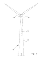
- a wind turbine 90 comprises a tower 92, a nacelle 94 at the tower top, the nacelle housing machine components, such as gearbox, generator etc. (not shown).
- a hub 96 supports a plurality of wind turbine blades 100.
- Fig. 2 shows a cross section of a wind turbine blade 100 according to the present invention.
- the blade comprises a main blade body 102 and a trailing edge section 104.
- the blade 100 comprises upper and lower skins 101 and 103. Trailing sections 105 and 107 of the main blade section may be flexible, elastic or springy, made e.g. from a suitable laminate.
- the main blade body 102 comprises spars 106 and 108. At a first projection 110 of spar 108, the trailing edge section 104 is movably connected to the main blade body at pivot 112.
- respective first ends of first and second actuator structures 118 and 120 are attached at pivots 122 and 124. Opposite second ends of the actuators 118 and 120 are attached at further pivots 126 and 128 to fulcrums 130 and 132 of the trailing edge section 104.
- Each of the actuator structures 118 and 120 comprises a stack of a plurality of piezoelectric elements 134, such as rings or circular plates of piezoelectric material.
- the stack of piezoelectric elements 134 and hence the actuator structures 118 and 120 are arranged so as to allow the actuator structures to operate as linear actuators for causing the trailing edge section 104 to move, deform or deflect relative to the main blade section 102.
- Displacement of the actuators 118 and 120 results in deflection of the trailing edge section 102 relative to the main blade section 102, as the trailing edge section 104 (flap) pivots around pivot joint 112.
- Operation of the actuators is appropriately controlled by a control system, which may e.g. cause the upper actuator 118 to extend its length and the lower actuator 120 to simultaneously reduce its length for deflection of the trailing edge section 104.
- the upper actuator 118 may be operated to reduce its length
- the lower actuator 120 may be operated to increase its length.
- the actuator structures 118 and 120 co-operate to provide a moment around the pivot joint 112, which is displaced from the points of attack at 126 and 128, with the fulcrums 130 and 132 acting as force amplifiers.
- Fig. 3 shows a first embodiment of the actuator structure 118 and 120 in more detail.
- the actuator structure shown comprises a force sensor 136 in the form of a dummy piezoelectric element, of which an electric signal may be tapped to measure the dynamic force that passes through in series, by quantifying the voltage or the charge that arises in it.
- Adjacent the stack of piezoelectric elements are insulating rings 138 and 140 of a ceramic material for protecting the actuators from lightning current.
- the stack of piezoelectric elements and the force sensor is held together under compressive load by a bolt 142 and a nut 144 in order to avoid the stack of piezoelectric elements to enter a tensile stress condition under the presence of an alternating wind load on the trailing edge section 104.
- the bolt head is optionally received in a housing element 144.
- Electrodes (not shown) for providing an operating voltage, charge or current to the stack of piezoelectric elements are connected to the stack of piezoelectric elements.
- Fig. 4 illustrates a second embodiment of the actuator structure 118 and 120 generally depicted in Fig. 2 .
- the actuator 118, 120 comprises a stack of piezoelectric elements 134, between which are arranged first activation electrodes 146 and second activation electrodes 148. Neighbouring piezoelectric elements share common electrodes 146 and 148, with the piezoelectric elements being arranged with their poling directions as indicated by arrows in Fig. 4 .
- a force sensor (not shown) may optionally be included in the stack of piezoelectric elements 134. At the respective ends of the stack of piezoelectric elements, insulating rings of a ceramic material are provided for lightning protection.
- the stack of piezoelectric elements 134 and the insulating rings 138, 140 are housed in U-shaped housing halves 150 and 152, which are held together by bolds 154 and 156, whereby the stack of piezoelectric elements is kept under compressive load in order to avoid the stack of piezoelectric elements to enter a tensile stress condition under the presence of an alternating wind load on the trailing edge section 104.
- the housing halves 150 and 152 form revolute joints 158 and 160 for attachment to the spar 108 of the main blade section and to the trailing edge section, respectively.
- a displacement sensor may be provided for measuring or determining the displacement of the actuators 118, 120.
- the stack 134 of piezoelectric elements is preferably controlled via electrodes, e.g. electrodes 146 and 148 as shown in the embodiment of Fig. 4 , to which a charge or current is provided in response to control commands generated in a control system (not shown).
Landscapes
- Engineering & Computer Science (AREA)
- Life Sciences & Earth Sciences (AREA)
- Sustainable Development (AREA)
- Sustainable Energy (AREA)
- Chemical & Material Sciences (AREA)
- Combustion & Propulsion (AREA)
- Mechanical Engineering (AREA)
- General Engineering & Computer Science (AREA)
- Physics & Mathematics (AREA)
- Fluid Mechanics (AREA)
- Wind Motors (AREA)
Applications Claiming Priority (2)
| Application Number | Priority Date | Filing Date | Title |
|---|---|---|---|
| US16366309P | 2009-03-26 | 2009-03-26 | |
| DKPA200900420A DK200900420A (en) | 2009-03-26 | 2009-03-26 | A wind turbine blade comprising a trailing edge flap and a piezoelectric actuator |
Publications (2)
| Publication Number | Publication Date |
|---|---|
| EP2233735A2 true EP2233735A2 (fr) | 2010-09-29 |
| EP2233735A3 EP2233735A3 (fr) | 2014-04-09 |
Family
ID=42224597
Family Applications (1)
| Application Number | Title | Priority Date | Filing Date |
|---|---|---|---|
| EP10157166.9A Withdrawn EP2233735A3 (fr) | 2009-03-26 | 2010-03-22 | Pale d'éolienne comportant un volet de bord de fuite et un actionneur piézoélectrique |
Country Status (4)
| Country | Link |
|---|---|
| US (1) | US7922450B2 (fr) |
| EP (1) | EP2233735A3 (fr) |
| CN (2) | CN101865076A (fr) |
| DK (1) | DK200900420A (fr) |
Cited By (14)
| Publication number | Priority date | Publication date | Assignee | Title |
|---|---|---|---|---|
| CN102085918A (zh) * | 2010-12-31 | 2011-06-08 | 北京控制工程研究所 | 星上挠性振动的二元智能结构控制装置 |
| GB2486876A (en) * | 2010-12-20 | 2012-07-04 | Vestas Wind Sys As | Wind turbine blade flap |
| EP2669509A1 (fr) * | 2012-05-29 | 2013-12-04 | SE Blades Technology B.V. | Actuateur |
| EP2998571A1 (fr) | 2014-09-19 | 2016-03-23 | Siemens Aktiengesellschaft | Dispositif influençant le levage d'une pale de rotor d'une éolienne |
| EP3128169A1 (fr) * | 2015-08-07 | 2017-02-08 | Siemens Aktiengesellschaft | Pale de rotor avec agencement d'actionneur |
| CN110107455A (zh) * | 2019-05-20 | 2019-08-09 | 沈阳航空航天大学 | 一种鱼尾摆动式垂直轴风力机叶片 |
| WO2019170656A1 (fr) | 2018-03-08 | 2019-09-12 | Mubea Carbo Tech Gmbh | Pale d'éolienne |
| US20210363961A1 (en) * | 2018-04-28 | 2021-11-25 | The Research Foundation For The State University Of New York | Flexible wind turbine blade with actively variable twist distribution |
| WO2022019854A1 (fr) | 2020-07-23 | 2022-01-27 | Tusas- Turk Havacilik Ve Uzay Sanayii Anonim Sirketi | Système de surface de commande |
| WO2022019857A1 (fr) | 2020-07-23 | 2022-01-27 | Tusas- Turk Havacilik Ve Uzay Sanayii Anonim Sirketi | Système de surface de commande |
| WO2022019856A1 (fr) | 2020-07-23 | 2022-01-27 | Tusas- Turk Havacilik Ve Uzay Sanayii Anonim Sirketi | Configuration d'actionneur |
| WO2022019852A1 (fr) * | 2020-07-23 | 2022-01-27 | Tusas- Turk Havacilik Ve Uzay Sanayii Anonim Sirketi | Mécanisme actionneur |
| WO2022019858A1 (fr) | 2020-07-23 | 2022-01-27 | Tusas- Turk Havacilik Ve Uzay Sanayii Anonim Sirketi | Mécanisme actionneur |
| EP4267847A4 (fr) * | 2020-12-22 | 2024-11-27 | Roar Ramde | Système de production d'énergie en mer |
Families Citing this family (31)
| Publication number | Priority date | Publication date | Assignee | Title |
|---|---|---|---|---|
| US8232664B2 (en) * | 2008-08-25 | 2012-07-31 | Mark R. Stroup | Vertical axis wind turbine |
| DK200900420A (en) * | 2009-03-26 | 2010-09-27 | Vestas Wind Sys As | A wind turbine blade comprising a trailing edge flap and a piezoelectric actuator |
| EP2333322A3 (fr) * | 2009-11-30 | 2017-02-22 | Vestas Wind Systems A/S | Mesure des charges sur des pales d'éolienne |
| PL2405129T3 (pl) * | 2010-07-06 | 2017-06-30 | Lm Wp Patent Holding A/S | Łopata turbiny wiatrowej o zmiennej krawędzi spływu |
| CN102305167B (zh) * | 2011-07-07 | 2014-03-19 | 安义 | 水流源与气流源动力子母舵叶片元 |
| US8602732B2 (en) | 2011-10-06 | 2013-12-10 | General Electric Company | Wind turbine rotor blade with passively modified trailing edge component |
| US8506248B2 (en) | 2011-10-06 | 2013-08-13 | General Electric Company | Wind turbine rotor blade with passively modified trailing edge component |
| EP2757254B1 (fr) * | 2013-01-21 | 2016-06-01 | Alstom Wind, S.L.U. | Pale de turbine d'éolienne |
| CN103291539B (zh) * | 2013-05-09 | 2015-05-13 | 哈尔滨工业大学 | 一种叶片摆翼的设计方法和一种带叶片摆翼的h型立轴风力机 |
| EP2865887B1 (fr) * | 2013-10-24 | 2016-06-01 | Alstom Renovables España, S.L. | Pale de turbine éolienne |
| DK2899395T3 (en) * | 2014-01-23 | 2017-07-24 | Alstom Renovables Espana Sl | Wind turbine blades |
| DK2908001T3 (da) | 2014-02-12 | 2017-01-02 | Siemens Ag | Midler til dæmpning af belastning på en vindmøllerotorvinge |
| WO2015139130A1 (fr) * | 2014-03-17 | 2015-09-24 | Manconi John William | Éolienne piézo-électrique améliorée |
| GB2537630B (en) * | 2015-04-21 | 2020-11-04 | Agustawestland Ltd | An aerofoil |
| US10442525B2 (en) * | 2016-05-07 | 2019-10-15 | Optivector Ltd | Rotor or propeller blade with dynamically variable geometry and other properties |
| DE102016116138A1 (de) | 2016-08-30 | 2018-03-01 | Wobben Properties Gmbh | Aktuatoreinrichtung für eine Windenergieanlage, Windenergieanlage und Montageverfahren |
| DE102017129708B4 (de) | 2017-12-13 | 2022-05-12 | cp.max Rotortechnik GmbH & Co. KG | Hinterkantenklappe für ein Rotorblatt |
| CN108298062B (zh) * | 2018-01-15 | 2021-03-12 | 上海理工大学 | 可自动约束的自适应襟翼 |
| DE102018100963A1 (de) * | 2018-01-17 | 2019-07-18 | Wobben Properties Gmbh | Windenergieanlage und Rotorblatt für eine Windenergieanlage |
| CN108374751B (zh) * | 2018-01-25 | 2020-01-21 | 上海理工大学 | 可自动开闭翼缝射流的分段式叶片装置 |
| EP3517773B1 (fr) | 2018-01-29 | 2020-08-12 | Siemens Gamesa Renewable Energy A/S | Ensemble de bord de fuite |
| DE102018104731A1 (de) * | 2018-03-01 | 2019-09-05 | Wobben Properties Gmbh | Aktuatoreinrichtung für eine Windenergieanlage, Windenergieanlage und Montageverfahren |
| CN110792554B (zh) * | 2018-08-03 | 2020-12-11 | 兰州理工大学 | 变形式风力发电机叶片 |
| US11408394B2 (en) * | 2018-09-17 | 2022-08-09 | Siemens Gamesa Renewable Energy A/S | Sensor device for an aerodynamic element |
| EP3730779A1 (fr) * | 2019-04-25 | 2020-10-28 | Siemens Gamesa Renewable Energy A/S | Système de tuyauterie de transmission de fluide pour pale de rotor d'éolienne |
| CN110486227B (zh) * | 2019-08-07 | 2021-10-19 | 河海大学 | 基于风环境主动防护的风力发电系统及其防护方法 |
| CN111749844A (zh) * | 2020-07-17 | 2020-10-09 | 中国人民解放军63821部队 | 一种具有可变后缘的垂直轴风力机叶片及垂直轴风力机 |
| EP4039965A1 (fr) * | 2021-02-05 | 2022-08-10 | Siemens Gamesa Renewable Energy A/S | Élément aérodynamique d'une pale d'une éolienne |
| DE102021005965B3 (de) | 2021-12-01 | 2022-11-10 | Friedrich Grimm | Rotorblatt für eine wind - oder wasserturbine sowie für ein drehflügelfahrzeug und insbesondere für einen hubschrauber |
| CN114837880B (zh) * | 2022-04-11 | 2025-02-14 | 上海交通大学 | 一种风力机智能降载叶片及其工作方法 |
| CN116163896B (zh) * | 2023-04-26 | 2023-07-11 | 山东科技大学 | 基于兆瓦级风力机叶片高频微振动测定及抑制系统 |
Citations (1)
| Publication number | Priority date | Publication date | Assignee | Title |
|---|---|---|---|---|
| WO2004088130A1 (fr) | 2003-03-31 | 2004-10-14 | Forskningscenter Risø | Regulation de puissance, de charges et/ou de stabilite d'une eolienne a axe horizontal au moyen d'une commande de geometrie d'aubes variable |
Family Cites Families (17)
| Publication number | Priority date | Publication date | Assignee | Title |
|---|---|---|---|---|
| DE2922885A1 (de) * | 1979-06-06 | 1980-12-18 | Wolfgang Rath | Zyklische klappensteuerung fuer windkraftanlagen |
| US4396852A (en) * | 1981-07-10 | 1983-08-02 | Hunt Arlon J | Windmill |
| FR2768994B1 (fr) * | 1997-09-30 | 2001-12-21 | Deutsch Zentr Luft & Raumfahrt | Profil |
| US6135713A (en) | 1999-01-19 | 2000-10-24 | The Mcdonnell Douglas Helicopter Company | Helicopter rotor blade flap actuator government interest |
| US6231013B1 (en) | 1999-06-16 | 2001-05-15 | Daimlerchrysler Ag | Airfoil member with a piezoelectrically actuated servo-flap |
| DE10054643B4 (de) * | 2000-11-03 | 2008-06-05 | Deutsches Zentrum für Luft- und Raumfahrt e.V. | Bauelement mit steuerbarer Verformung |
| US6481667B1 (en) * | 2001-03-05 | 2002-11-19 | Northrop Grumman Corporation | System and method for deflecting an aerodynamic control surface |
| DE10126918A1 (de) | 2001-06-01 | 2002-12-19 | Eads Deutschland Gmbh | Hochleistungspiezoaktuator |
| DE10214984B4 (de) * | 2002-04-04 | 2006-01-19 | Eads Deutschland Gmbh | Aktorik- und Sensoriksystem für Verbundstrukturen |
| US6769873B2 (en) * | 2002-10-08 | 2004-08-03 | The United States Of America As Represented By The Secretary Of The Navy | Dynamically reconfigurable wind turbine blade assembly |
| EP1597476A1 (fr) | 2003-02-18 | 2005-11-23 | Forskningscenter Riso | Methode de commande de la charge aerodynamique d'une eolienne en fonction de la mesure de l'ecoulement local au niveau des pales |
| DK200300670A (da) | 2003-05-05 | 2004-11-06 | Lm Glasfiber As | Vindmölleving med opdriftsregulerende organer |
| EP1745214B2 (fr) | 2004-05-11 | 2020-04-29 | Weidmüller Monitoring Systems GmbH | Procede de commande des pales-rotor d'une installation eolienne et installation eolienne pourvue d'un systeme de mesure et destinee a la mise en oeuvre de ce procede |
| US7360996B2 (en) * | 2005-12-07 | 2008-04-22 | General Electric Company | Wind blade assembly and method for damping load or strain |
| CN101207313B (zh) * | 2006-12-22 | 2011-03-30 | 财团法人工业技术研究院 | 具有复合式发电机的发电装置及其发电方法 |
| CN101874158A (zh) * | 2007-10-29 | 2010-10-27 | 维斯塔斯风力系统有限公司 | 风轮机叶片以及用于控制叶片上的载荷的方法 |
| DK200900420A (en) * | 2009-03-26 | 2010-09-27 | Vestas Wind Sys As | A wind turbine blade comprising a trailing edge flap and a piezoelectric actuator |
-
2009
- 2009-03-26 DK DKPA200900420A patent/DK200900420A/en not_active Application Discontinuation
-
2010
- 2010-03-22 EP EP10157166.9A patent/EP2233735A3/fr not_active Withdrawn
- 2010-03-24 US US12/730,810 patent/US7922450B2/en not_active Expired - Fee Related
- 2010-03-26 CN CN201010188021A patent/CN101865076A/zh active Pending
- 2010-03-26 CN CN2010202103457U patent/CN201757024U/zh not_active Expired - Fee Related
Patent Citations (1)
| Publication number | Priority date | Publication date | Assignee | Title |
|---|---|---|---|---|
| WO2004088130A1 (fr) | 2003-03-31 | 2004-10-14 | Forskningscenter Risø | Regulation de puissance, de charges et/ou de stabilite d'une eolienne a axe horizontal au moyen d'une commande de geometrie d'aubes variable |
Cited By (21)
| Publication number | Priority date | Publication date | Assignee | Title |
|---|---|---|---|---|
| GB2486876A (en) * | 2010-12-20 | 2012-07-04 | Vestas Wind Sys As | Wind turbine blade flap |
| CN102085918B (zh) * | 2010-12-31 | 2013-03-13 | 北京控制工程研究所 | 星上挠性振动的二元智能结构控制装置及控制方法 |
| CN102085918A (zh) * | 2010-12-31 | 2011-06-08 | 北京控制工程研究所 | 星上挠性振动的二元智能结构控制装置 |
| EP2669509A1 (fr) * | 2012-05-29 | 2013-12-04 | SE Blades Technology B.V. | Actuateur |
| EP2998571A1 (fr) | 2014-09-19 | 2016-03-23 | Siemens Aktiengesellschaft | Dispositif influençant le levage d'une pale de rotor d'une éolienne |
| US10408192B2 (en) | 2014-09-19 | 2019-09-10 | Siemens Gamesa Renewable Energy A/S | Lift influencing device for a rotor blade of a wind turbine |
| EP3128169A1 (fr) * | 2015-08-07 | 2017-02-08 | Siemens Aktiengesellschaft | Pale de rotor avec agencement d'actionneur |
| WO2017025352A1 (fr) * | 2015-08-07 | 2017-02-16 | Siemens Aktiengesellschaft | Pale de rotor avec agencement d'actionneur |
| WO2019170656A1 (fr) | 2018-03-08 | 2019-09-12 | Mubea Carbo Tech Gmbh | Pale d'éolienne |
| US20210363961A1 (en) * | 2018-04-28 | 2021-11-25 | The Research Foundation For The State University Of New York | Flexible wind turbine blade with actively variable twist distribution |
| CN110107455A (zh) * | 2019-05-20 | 2019-08-09 | 沈阳航空航天大学 | 一种鱼尾摆动式垂直轴风力机叶片 |
| WO2022019854A1 (fr) | 2020-07-23 | 2022-01-27 | Tusas- Turk Havacilik Ve Uzay Sanayii Anonim Sirketi | Système de surface de commande |
| WO2022019857A1 (fr) | 2020-07-23 | 2022-01-27 | Tusas- Turk Havacilik Ve Uzay Sanayii Anonim Sirketi | Système de surface de commande |
| WO2022019856A1 (fr) | 2020-07-23 | 2022-01-27 | Tusas- Turk Havacilik Ve Uzay Sanayii Anonim Sirketi | Configuration d'actionneur |
| WO2022019852A1 (fr) * | 2020-07-23 | 2022-01-27 | Tusas- Turk Havacilik Ve Uzay Sanayii Anonim Sirketi | Mécanisme actionneur |
| WO2022019858A1 (fr) | 2020-07-23 | 2022-01-27 | Tusas- Turk Havacilik Ve Uzay Sanayii Anonim Sirketi | Mécanisme actionneur |
| US12054240B2 (en) | 2020-07-23 | 2024-08-06 | Tusas-Turk Havacilik Ve Uzay Sanayii As | Actuator setup |
| US12201027B2 (en) | 2020-07-23 | 2025-01-14 | Tusas-Turk Havacilik Ve Uzay Sanayii Anonim Sirketi | Actuator mechanism |
| US12325508B2 (en) | 2020-07-23 | 2025-06-10 | Tusas- Turk Havacilik Ve Uzay Sanayii Anonim Sirketi | Control surface system |
| US12377963B2 (en) | 2020-07-23 | 2025-08-05 | Tusas-Turk Havacilik Ve Uzay Sanayii Anonim Sirketi | Control surface system with actuator made of electroactive material |
| EP4267847A4 (fr) * | 2020-12-22 | 2024-11-27 | Roar Ramde | Système de production d'énergie en mer |
Also Published As
| Publication number | Publication date |
|---|---|
| CN201757024U (zh) | 2011-03-09 |
| DK200900420A (en) | 2010-09-27 |
| CN101865076A (zh) | 2010-10-20 |
| EP2233735A3 (fr) | 2014-04-09 |
| US7922450B2 (en) | 2011-04-12 |
| US20100247314A1 (en) | 2010-09-30 |
Similar Documents
| Publication | Publication Date | Title |
|---|---|---|
| US7922450B2 (en) | Wind turbine blade comprising a trailing edge flap and a piezoelectric actuator | |
| CA2521045C (fr) | Regulation de puissance, de charges et/ou de stabilite d'une eolienne a axe horizontal au moyen d'une commande de geometrie d'aubes variable | |
| US8087888B2 (en) | Wind turbine blade with cambering flaps | |
| EP2222955B1 (fr) | Aube d'éolienne et procédé permettant de réguler la charge s'exerçant sur une aube | |
| US10451037B2 (en) | Wind turbine blade | |
| US10247169B2 (en) | Means for alleviating strain on a wind turbine rotor blade | |
| US20140356181A1 (en) | Wind turbine blade having a tensile-only stiffener for passive control of flap movement | |
| EP2273106B1 (fr) | Contrôle de la séparation aérodynamique d'éolienne | |
| CN105408625A (zh) | 基于叶片上测量的负荷和加速度的风力涡轮机的操作方法及装置 | |
| CN108005848B (zh) | 基于sma差压反馈的抑制风力机挥舞共振的智能变桨系统 | |
| EP2848805A1 (fr) | Procédé de fonctionnement d'une éolienne | |
| KR20150080845A (ko) | 풍력 발전기용 블레이드의 제어장치, 제어방법, 및 이를 이용하는 풍력 발전기 | |
| CN115076027A (zh) | 基于风致振动的压电能量俘获装置 | |
| EP3146201A1 (fr) | Dispositif aérodynamique d'une pale de rotor d'une éolienne | |
| Madsen et al. | A morphing trailing edge flap system for wind turbine blades | |
| US12215668B2 (en) | Wind turbine component, wind turbine, and method for manufacturing of a wind turbine component | |
| US10422318B2 (en) | Wind turbine blade | |
| CN106968896A (zh) | 风力涡轮机转子叶片的偏转的确定 | |
| Opitz et al. | Bench test of a full-scale active twist blade segment | |
| Hulskamp et al. | Smart dynamic rotor control: Part 1, Design of a smart rotor. | |
| DK201270436A (en) | Wind turbine blade having a flap | |
| Vos | Post-buckled precompressed elements: a new class of flight control actuators enhancing morphing wing uavs |
Legal Events
| Date | Code | Title | Description |
|---|---|---|---|
| PUAI | Public reference made under article 153(3) epc to a published international application that has entered the european phase |
Free format text: ORIGINAL CODE: 0009012 |
|
| 17P | Request for examination filed |
Effective date: 20100422 |
|
| AK | Designated contracting states |
Kind code of ref document: A2 Designated state(s): AT BE BG CH CY CZ DE DK EE ES FI FR GB GR HR HU IE IS IT LI LT LU LV MC MK MT NL NO PL PT RO SE SI SK SM TR |
|
| AX | Request for extension of the european patent |
Extension state: AL BA ME RS |
|
| RAP1 | Party data changed (applicant data changed or rights of an application transferred) |
Owner name: VESTAS WIND SYSTEMS A/S |
|
| PUAL | Search report despatched |
Free format text: ORIGINAL CODE: 0009013 |
|
| AK | Designated contracting states |
Kind code of ref document: A3 Designated state(s): AT BE BG CH CY CZ DE DK EE ES FI FR GB GR HR HU IE IS IT LI LT LU LV MC MK MT NL NO PL PT RO SE SI SK SM TR |
|
| AX | Request for extension of the european patent |
Extension state: AL BA ME RS |
|
| RIC1 | Information provided on ipc code assigned before grant |
Ipc: F03D 3/06 20060101AFI20140228BHEP Ipc: F03D 1/06 20060101ALI20140228BHEP Ipc: F03D 7/02 20060101ALI20140228BHEP |
|
| STAA | Information on the status of an ep patent application or granted ep patent |
Free format text: STATUS: THE APPLICATION IS DEEMED TO BE WITHDRAWN |
|
| 18D | Application deemed to be withdrawn |
Effective date: 20141001 |