EP2233859B1 - Dispositif concentrateur-capteur d'énergie solaire - Google Patents
Dispositif concentrateur-capteur d'énergie solaire Download PDFInfo
- Publication number
- EP2233859B1 EP2233859B1 EP08868504.5A EP08868504A EP2233859B1 EP 2233859 B1 EP2233859 B1 EP 2233859B1 EP 08868504 A EP08868504 A EP 08868504A EP 2233859 B1 EP2233859 B1 EP 2233859B1
- Authority
- EP
- European Patent Office
- Prior art keywords
- supporting
- concentrator
- reflector
- profiles
- parabola
- Prior art date
- Legal status (The legal status is an assumption and is not a legal conclusion. Google has not performed a legal analysis and makes no representation as to the accuracy of the status listed.)
- Not-in-force
Links
Images




Classifications
-
- F—MECHANICAL ENGINEERING; LIGHTING; HEATING; WEAPONS; BLASTING
- F24—HEATING; RANGES; VENTILATING
- F24S—SOLAR HEAT COLLECTORS; SOLAR HEAT SYSTEMS
- F24S23/00—Arrangements for concentrating solar-rays for solar heat collectors
- F24S23/70—Arrangements for concentrating solar-rays for solar heat collectors with reflectors
-
- F—MECHANICAL ENGINEERING; LIGHTING; HEATING; WEAPONS; BLASTING
- F24—HEATING; RANGES; VENTILATING
- F24S—SOLAR HEAT COLLECTORS; SOLAR HEAT SYSTEMS
- F24S23/00—Arrangements for concentrating solar-rays for solar heat collectors
- F24S23/70—Arrangements for concentrating solar-rays for solar heat collectors with reflectors
- F24S23/74—Arrangements for concentrating solar-rays for solar heat collectors with reflectors with trough-shaped or cylindro-parabolic reflective surfaces
-
- F—MECHANICAL ENGINEERING; LIGHTING; HEATING; WEAPONS; BLASTING
- F24—HEATING; RANGES; VENTILATING
- F24S—SOLAR HEAT COLLECTORS; SOLAR HEAT SYSTEMS
- F24S25/00—Arrangement of stationary mountings or supports for solar heat collector modules
- F24S25/30—Arrangement of stationary mountings or supports for solar heat collector modules using elongate rigid mounting elements extending substantially along the supporting surface, e.g. for covering buildings with solar heat collectors
- F24S25/33—Arrangement of stationary mountings or supports for solar heat collector modules using elongate rigid mounting elements extending substantially along the supporting surface, e.g. for covering buildings with solar heat collectors forming substantially planar assemblies, e.g. of coplanar or stacked profiles
-
- F—MECHANICAL ENGINEERING; LIGHTING; HEATING; WEAPONS; BLASTING
- F24—HEATING; RANGES; VENTILATING
- F24S—SOLAR HEAT COLLECTORS; SOLAR HEAT SYSTEMS
- F24S25/00—Arrangement of stationary mountings or supports for solar heat collector modules
- F24S25/60—Fixation means, e.g. fasteners, specially adapted for supporting solar heat collector modules
- F24S25/63—Fixation means, e.g. fasteners, specially adapted for supporting solar heat collector modules for fixing modules or their peripheral frames to supporting elements
- F24S25/632—Side connectors; Base connectors
-
- F—MECHANICAL ENGINEERING; LIGHTING; HEATING; WEAPONS; BLASTING
- F24—HEATING; RANGES; VENTILATING
- F24S—SOLAR HEAT COLLECTORS; SOLAR HEAT SYSTEMS
- F24S30/00—Arrangements for moving or orienting solar heat collector modules
- F24S30/20—Arrangements for moving or orienting solar heat collector modules for linear movement
-
- F—MECHANICAL ENGINEERING; LIGHTING; HEATING; WEAPONS; BLASTING
- F24—HEATING; RANGES; VENTILATING
- F24S—SOLAR HEAT COLLECTORS; SOLAR HEAT SYSTEMS
- F24S30/00—Arrangements for moving or orienting solar heat collector modules
- F24S30/40—Arrangements for moving or orienting solar heat collector modules for rotary movement
- F24S30/42—Arrangements for moving or orienting solar heat collector modules for rotary movement with only one rotation axis
- F24S30/425—Horizontal axis
-
- F—MECHANICAL ENGINEERING; LIGHTING; HEATING; WEAPONS; BLASTING
- F24—HEATING; RANGES; VENTILATING
- F24S—SOLAR HEAT COLLECTORS; SOLAR HEAT SYSTEMS
- F24S20/00—Solar heat collectors specially adapted for particular uses or environments
- F24S20/20—Solar heat collectors for receiving concentrated solar energy, e.g. receivers for solar power plants
- F24S2020/23—Solar heat collectors for receiving concentrated solar energy, e.g. receivers for solar power plants movable or adjustable
-
- F—MECHANICAL ENGINEERING; LIGHTING; HEATING; WEAPONS; BLASTING
- F24—HEATING; RANGES; VENTILATING
- F24S—SOLAR HEAT COLLECTORS; SOLAR HEAT SYSTEMS
- F24S23/00—Arrangements for concentrating solar-rays for solar heat collectors
- F24S23/70—Arrangements for concentrating solar-rays for solar heat collectors with reflectors
- F24S2023/87—Reflectors layout
- F24S2023/872—Assemblies of spaced reflective elements on common support, e.g. Fresnel reflectors
-
- F—MECHANICAL ENGINEERING; LIGHTING; HEATING; WEAPONS; BLASTING
- F24—HEATING; RANGES; VENTILATING
- F24S—SOLAR HEAT COLLECTORS; SOLAR HEAT SYSTEMS
- F24S25/00—Arrangement of stationary mountings or supports for solar heat collector modules
- F24S2025/01—Special support components; Methods of use
- F24S2025/023—Means for preventing theft; Locking means
-
- F—MECHANICAL ENGINEERING; LIGHTING; HEATING; WEAPONS; BLASTING
- F24—HEATING; RANGES; VENTILATING
- F24S—SOLAR HEAT COLLECTORS; SOLAR HEAT SYSTEMS
- F24S25/00—Arrangement of stationary mountings or supports for solar heat collector modules
- F24S25/60—Fixation means, e.g. fasteners, specially adapted for supporting solar heat collector modules
- F24S2025/6007—Fixation means, e.g. fasteners, specially adapted for supporting solar heat collector modules by using form-fitting connection means, e.g. tongue and groove
-
- F—MECHANICAL ENGINEERING; LIGHTING; HEATING; WEAPONS; BLASTING
- F24—HEATING; RANGES; VENTILATING
- F24S—SOLAR HEAT COLLECTORS; SOLAR HEAT SYSTEMS
- F24S30/00—Arrangements for moving or orienting solar heat collector modules
- F24S2030/10—Special components
- F24S2030/13—Transmissions
- F24S2030/136—Transmissions for moving several solar collectors by common transmission elements
-
- Y—GENERAL TAGGING OF NEW TECHNOLOGICAL DEVELOPMENTS; GENERAL TAGGING OF CROSS-SECTIONAL TECHNOLOGIES SPANNING OVER SEVERAL SECTIONS OF THE IPC; TECHNICAL SUBJECTS COVERED BY FORMER USPC CROSS-REFERENCE ART COLLECTIONS [XRACs] AND DIGESTS
- Y02—TECHNOLOGIES OR APPLICATIONS FOR MITIGATION OR ADAPTATION AGAINST CLIMATE CHANGE
- Y02B—CLIMATE CHANGE MITIGATION TECHNOLOGIES RELATED TO BUILDINGS, e.g. HOUSING, HOUSE APPLIANCES OR RELATED END-USER APPLICATIONS
- Y02B10/00—Integration of renewable energy sources in buildings
- Y02B10/20—Solar thermal
-
- Y—GENERAL TAGGING OF NEW TECHNOLOGICAL DEVELOPMENTS; GENERAL TAGGING OF CROSS-SECTIONAL TECHNOLOGIES SPANNING OVER SEVERAL SECTIONS OF THE IPC; TECHNICAL SUBJECTS COVERED BY FORMER USPC CROSS-REFERENCE ART COLLECTIONS [XRACs] AND DIGESTS
- Y02—TECHNOLOGIES OR APPLICATIONS FOR MITIGATION OR ADAPTATION AGAINST CLIMATE CHANGE
- Y02E—REDUCTION OF GREENHOUSE GAS [GHG] EMISSIONS, RELATED TO ENERGY GENERATION, TRANSMISSION OR DISTRIBUTION
- Y02E10/00—Energy generation through renewable energy sources
- Y02E10/40—Solar thermal energy, e.g. solar towers
-
- Y—GENERAL TAGGING OF NEW TECHNOLOGICAL DEVELOPMENTS; GENERAL TAGGING OF CROSS-SECTIONAL TECHNOLOGIES SPANNING OVER SEVERAL SECTIONS OF THE IPC; TECHNICAL SUBJECTS COVERED BY FORMER USPC CROSS-REFERENCE ART COLLECTIONS [XRACs] AND DIGESTS
- Y02—TECHNOLOGIES OR APPLICATIONS FOR MITIGATION OR ADAPTATION AGAINST CLIMATE CHANGE
- Y02E—REDUCTION OF GREENHOUSE GAS [GHG] EMISSIONS, RELATED TO ENERGY GENERATION, TRANSMISSION OR DISTRIBUTION
- Y02E10/00—Energy generation through renewable energy sources
- Y02E10/40—Solar thermal energy, e.g. solar towers
- Y02E10/47—Mountings or tracking
Definitions
- the present invention generally relates to a solar energy concentrator-collector device and more specifically to a solar energy concentrator-collector device comprising a stationary reflector for reflecting and concentrating the sun's rays and a mobile receiver moved by a tracking mechanism for following the maximum confluence of the sun's rays reflected by the fixed reflector as the relative position of the sun changes.
- Solar collectors configured to collect thermal or photovoltaic energy from the sun's rays directly impinging on the same are known. However, the energy efficiency of such collectors is relatively low due to the low energy density of the impinging rays.
- solar collectors of this type which use thermal energy of the sun's rays to heat a heat-transfer fluid. However, the heat-transfer fluid can only reach rather low temperatures which do not allow the thermal energy to be transformed into mechanical work.
- Patent US-A-3868823 discloses a concentrator-collector device comprising reflective surfaces suitable for reflecting substantially parallel impinging rays towards respective linear foci which move in a predetermined path in response to changes in the angle of the impinging rays, linear receivers arranged for receiving the reflected rays, and tracking mechanisms driven to move the receivers in coincidence with the mentioned linear foci as the linear foci shift along said predetermined path.
- Each reflective surface can be a continuous concave surface or it can be formed by different planar segments.
- the reflective surfaces are arranged to reflect the sun's rays and the receiver includes a duct for conveying a heat-transfer fluid which starts to boil because of the heating effect of the sun's concentrated rays, such that the resulting steam can be used to generate mechanical work.
- Patent GB-A-1581253 describes a concentrator-collector device similar to that of the mentioned patent US-A-3868823 , in which the reflective surfaces of the fixed reflector are supported on a sandwich structure made up of an upper sheet of metal, a lower sheet of metal and rigid insulating foam between both.
- the reflective surfaces are provided by a polished outer surface of the upper sheet of metal.
- linear receivers are integrated in a mobile structure supported by a plurality of pivoting supporting arms assembled on a fixed structure supporting the reflector, such that the mobile structure, the pivoting supporting arms and the fixed structure function like an articulated parallelogram for guiding the movement of all the receivers in unison with respect to their respective reflective surfaces along a circular path selected for following the maximum concentration of the sun's reflected rays.
- a tracking mechanism driven by a motor is connected by means of a drive arm to the mobile structure to move the mobile structure along a portion of said circular path synchronously with the relative movement of the sun.
- the relative positions between the reflective surfaces and the receivers are critical for assuring that the linear receivers coincide at all times with the areas of maximum confluence of reflected rays.
- a classic process for installing a concentrator-collector device of this type comprises fixing the reflective surfaces on a fixed structure, building the mobile structure including the linear receivers and installing the mobile structure on the fixed structure by means of the pivoting arms and the tracking mechanism, all using the measurement of distances, levels, plumb bobs, etc. in situ, and performing cutting, drilling, welding operations, etc. in situ.
- This classic process has been shown to be rather inoperative due to the time consumed and the low level of precision obtained.
- Another aspect to be taken into account is how to determine the path that a linear receiver must follow in order to follow the maximum concentration of the sun's rays reflected by a reflective surface in the form of a ruled parabolic or approximately parabolic concave surface when the angle of incidence of the sun's rays changes as the relative position of the sun changes.
- a reflective parallel ruled parabolic surface the sun's reflected rays are concentrated only in a linear focus, which coincides with the focus of the parabola, when the sun's rays have normal incidence, i.e., parallel to the axis of the parabola.
- the maximum concentration of the rays is scattered in the area of a triangle formed between the rays reflected from a first end edge, from a second opposite end edge and from the center of the reflector.
- the mentioned triangle increases its size as the angle of incidence of the sun's rays moves away from the normal, i.e., the dispersion of the reflected rays is greater the more obliquely the sun's rays impinge on the reflector.
- the growth rate of the triangle reduces the greater the distance from the focus to the vertex of the parabola in relation to the width between opposite end edges of the reflector.
- Patent JP-A-10026423 describes a solar energy concentrator-collector device provided with a fixed concave reflector and a mobile receiver connected to a tracking mechanism capable of moving the mobile receiver along a path which follows the locus of the centers of imaginary circles inscribed in the mentioned triangles formed between the rays reflected from the right end, from the left end and from the center of the reflector as the angle of incidence of the sun's rays changes. There are established limit angles of incidence to the right and the left of the normal, for which the size of the triangle is maximum.
- the receiver is cylindrical in shape and has a diameter equal to that of the imaginary circle inscribed in the maximum sized triangle, which assures that the receiver will collect all the rays reflected by the reflector along its entire path.
- a drawback of the approach used in the mentioned patent JP-A-10026423 is that it does not take into account other factors which would allow optimizing the performance of the device using a smaller sized receiver, such as, for example, the fact that the energy of the concentrated rays in the triangle is not uniform, being higher in the proximities of the side of the triangle formed by the rays reflected from the center of the reflector and lower in the proximities of the opposite vertex.
- solar collector device is used to designate a device the function of which is to transform solar radiation into thermal energy (thermal solar collector device) or electric energy (photovoltaic solar collector device), which can be made up of several sub-systems such as a receiver, reflector, tracking mechanism.
- receiver is used to designate a component of a solar collector in which the transformation of the solar radiation into thermal or electric energy takes place.
- reflector-concentrator is used to designate a sub-system present in a solar collector the function of which is to concentrate the solar radiation and direct it towards the receiver using a high specular reflectance surface as a means for concentrating the energy.
- linear focus is used to designate an area of the space where the radiation reflected by the reflector-concentrator reaches its maximum density and which has an elongated, substantially rectilinear shape.
- a linear focus is produced by a reflective parallel ruled concave surface, for example, a reflective surface with a parabolic or approximately parabolic cross-section, several reflective surface sections, each with a parabolic or approximately parabolic cross-section, or a plurality of planar reflective surface sections arranged like a Fresnel mirror.
- the linear focus although in some theoretical cases can have the shape of a geometric line, in practice it takes up a certain elongated, approximately prismatic volume in space (see, for example, patent JP-A-10026423 ).
- the term "tracking mechanism" is used to designate a system which allows the positioning of either the reflector-concentrator, the receiver, or the assembly of both, according to the position of the sun, such that the linear focus produced by the reflector-concentrator at all times coincides with the position of the receiver.
- the present invention contributes to mitigating drawbacks of the prior art by providing a solar energy concentrator-collector device built from modular elements prepared for being assembled or fixed in situ using conventional fixing means, such as screwing elements or the like, or retaining elements having quick action by elastic deformation.
- the modular elements are provided with respective positioning configurations suitable for being mutually coupled during the assembling or fixing operations to provide precise positioning of the different modular elements. This allows the quick and easy installation of the device on a fixed supporting structure, such as, for example, a roof of a building or a structure made on purpose, with great precision in the relative positions of its components in comparison with other devices of the prior art.
- the solar energy concentrator-collector device of the present invention comprises a stationary reflector-concentrator formed by a plurality of reflector-concentrator modules arranged forming a matrix of longitudinal and transverse rows, where each of said reflector-concentrator modules comprises a frame to which at least one upper element carrying at least one reflective surface portion is fixed.
- Each reflective surface portion is concave and elongated and is configured to reflect the sun's rays and concentrate them in a linear focus parallel to a longitudinal direction thereof.
- the stationary reflector-concentrator the reflective surface portions are arranged aligned in the longitudinal rows forming, as a whole, reflective parallel elongated concave surfaces next to one another.
- the reflective surfaces are joined to a stationary structure formed by a plurality of parallel supporting profiles and by the frames themselves of the reflector-concentrator modules.
- the solar energy concentrator-collector device furthermore comprises a mobile receiver with a plurality of elongated mutually parallel receptor elements arranged parallel to the direction of said linear foci and joined to a mobile structure, and a tracking mechanism connected to said stationary structure and to said mobile structure in order to support and move the mobile structure on the reflective surfaces of the stationary reflector-concentrator in a path so that said receptor elements follow the maximum confluence of the sun's rays reflected by the reflective surfaces as the relative position of the sun changes.
- the mentioned tracking mechanism may comprise at least three base bodies fixed to at least two of the supporting profiles by means of conventional fixing means, and each of said base bodies rotationally supports at least one supporting shaft on which a pivoting arm linked to the mobile structure for guiding the movements of the mobile structure is assembled.
- Each base body of the tracking mechanism comprises first receiver positioning configurations precisely positioned with respect to said supporting shaft, and second receiver positioning configurations precisely positioned with respect to said second module positioning configurations are provided in the corresponding supporting profiles, or in auxiliary parts fixed thereto.
- the mentioned first receiver positioning configurations cooperate with said second receiver positioning configurations in order to position each base body in a predetermined operative position in relation to the corresponding supporting profile and thereby assuring a predetermined degree of precision for said path of the mobile receiver in relation to said stationary reflector-concentrator.
- a series of elements making up the structure and the tracking mechanism of the solar energy concentrator-collector device which are connected to one another by a chain of mutually coupled positioning configurations which guarantee the correct positioning of the mobile receiver with respect to the stationary reflector-concentrator, are arranged between the collectors of the mobile receiver and the reflector-concentrator modules of the stationary reflector-concentrator.
- the present invention provides an optimized path for the receptor elements in relation to the reflecting elements.
- the mentioned optimized path of the receptor element has been obtained from an iterative theoretical calculation for different shapes and proportions of the reflective surface portion and for different ranges of incidence conditions of the sun's rays simulating all the seasons of the year.
- the calculations have been performed taking many factors into account, for example, the energy of the concentrated rays in the mentioned triangle is higher in the proximities of the side of the triangle formed by the rays reflected from the center of the reflector than in the proximities of the opposite vertex.
- an optimal reflective surface has substantially the shape of a ruled surface having a substantially parabolic cross-section with two longitudinal side edges, a parabola vertex, a parabola axis and a linear focus coinciding with the parabola focus.
- the two mentioned longitudinal side edges are generally equidistant to said parabola vertex.
- an optimal circular path for a collecting element passes through said parabola focus and has a center on said parabola axis, a lower point in the lower intersection of the path with the parabola axis, and a diameter slightly greater than a distance between the parabola focus and said parabola vertex.
- the optimal value for the ratio of the diameter of the circular path with respect to said distance from the parabola focus to the parabola vertex is within the range 1 ⁇ D/FV ⁇ 1.10, i.e., the diameter is greater than the distance from the parabola focus to the parabola vertex but less than or equal to 1.10 times the distance from the parabola focus to the parabola vertex.
- a likewise significant parameter is the ratio of the width, i.e., the distance between the side edges of the reflective surface, with respect to the diameter of the circular path. It has been found that an optimal value for this parameter is in the range of 1:0.9 to 1:2.0.
- the present invention provides a solar energy concentrator-collector device which can be installed in a relatively easy manner with a guarantee in the precision of the relative positioning of its components and with an optimized path for the receptor elements of the mobile receiver.
- a solar energy concentrator-collector device comprising a stationary reflector-concentrator 1 joined to a stationary structure 21, a mobile receiver 2 joined to a mobile structure 3 and a tracking mechanism 4 connected to the mentioned stationary structure 21 and mobile structure 3 in order to support and move said mobile receiver 2 with respect to said stationary reflector-concentrator 1.
- the stationary reflector-concentrator 1 includes a plurality of reflector-concentrator modules 5 (one of which is shown in Figure 2 ) arranged forming a matrix of longitudinal and transverse rows and connected to a plurality of parallel supporting profiles 13a, 13b, 13c for forming a stationary structure 21.
- each of said reflector-concentrator modules 5 comprises a frame 6 to which an upper element 18 having a reflective surface is fixed.
- the upper element 18 is an upper sheet of metal defining two reflective concave arched surface portions 8 and side extensions 18a bent downwards.
- the reflective surface portions 8 have a polished reflective outer surface.
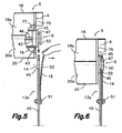
- the mentioned frame is formed, for example, by a pair of opposite end plates 75 closing the reflector-concentrator module 5 at its two longitudinal ends, connected to one another by internal longitudinal connection members 76 ( Figure 5 ).
- the reflector-concentrator module 5 furthermore comprises a lower sheet 20 with side extensions 20a bent upwards, and a filler material 77 ( Figure 5 ), such as, for example, expanded polyurethane, arranged between the upper element 18, the lower sheet 20 and the end plates 75. Furthermore, the filler material 77 is adhered to the upper element 18, to the lower sheet 20 and to the frame 6, said longitudinal connection members 76 of the frame 6 being embedded in the filler material 77.
- the filler material 77 is rigid enough to precisely guarantee a predetermined stable operative position of the upper element 18, and accordingly of the reflective surface portions 8, in relation to the frame 6.
- the reflector-concentrator module 5 could comprise one single reflective surface portion 8, or more than two of them, and the reflective surfaces could be provided by any number of additional reflective elements joined to the upper element 18 instead of being a polished surface thereof.
- Each reflective surface portion 8 of the reflector-concentrator module 5 substantially has the form of a ruled concave surface, elongated, configured to reflect the sun's rays and concentrate them in a linear focus parallel to a longitudinal direction indicated by means of the arrow DL in the figures.
- the reflective surface portions 8 of the reflector-concentrator modules 5 forming longitudinal rows are aligned forming said elongated reflective surfaces arranged parallel next to one another to concentrate the sun's reflected rays in a plurality of respective elongated linear foci.
- the mobile structure 3 of the mobile receiver 2 is formed by a plurality of longitudinal profiles 33 and transverse profiles 34a, 34b connected to one another forming a grid in which a plurality of elongated receptor elements 35 are installed forming alignments arranged parallel to the direction of said linear foci F. There is an alignment of receptor elements 35 for each alignment of reflective surface portions 8 and accordingly for each linear focus. The receptor elements 35 are supported at their ends between every two of said transverse profiles 34a, 34b in the grid of the mobile structure 3.
- the mentioned tracking mechanism 4 comprises four base bodies 10 fixed to two of the supporting profiles 13a, and each of said base bodies 10 rotationally supports a supporting shaft 11 on which a pivoting arm 37 connected to the mobile structure 3 for guiding the movements of the mobile structure 3 is assembled.
- the tracking mechanism 4 is motor-driven and controlled for moving the mobile structure 3 above said stationary reflector-concentrator 1 in a path so that the receptor elements 35 follow the maximum confluence of the sun's rays reflected by the reflective surfaces as the relative position of the sun changes.
- the number of base bodies 10 is not limited to four, although it will be understood that at least three base bodies 10 fixed to at least two of the supporting profiles 13a are necessary for supporting the mobile structure 3.
- the supporting profiles 13a, 13b, 13c are arranged mutually parallel and transverse to the direction of said linear foci F, i.e., transverse to the longitudinal direction DL.
- the frames 6 of the reflector-concentrator modules 5 of each transverse row are fixed at their opposite ends to two of said supporting profiles 13a, 13b, 13c.
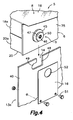
- the frame 6 of each reflector-concentrator module 5 comprises first module positioning configurations 9 (best shown in Figure 4 ) cooperating with second module positioning configurations 14 provided in said supporting profiles 13a, 13b, 13c in order to position each reflector-concentrator module 5, and accordingly the corresponding reflective surface portions 8, in a predetermined operative position in relation to the supporting profiles 13a, 13b, 13c.
- Figure 3 shows three different types of supporting profiles 13a, 13b, 13c which, together with the frames 6 of the reflector-concentrator modules 5, form the stationary structure 21 of the concentrator-collector device.
- the stationary structure 21 comprises two first supporting profiles 13a and a second supporting profile 13b, each of which is arranged between two adjacent transverse rows of reflector-concentrator modules 5.
- Both the first supporting profiles 13a and the second supporting profile 13b have the shape of a channel open at the top defining a pair of facing upright walls 40 in which the corresponding second module positioning configurations 14 are provided.
- the two facing upright walls 40 extend from side edges of a bottom wall 41 and are significantly separated in order to allow housing the base bodies 10 of the tracking mechanism 4 between the same.
- the stationary structure 21 furthermore comprises two third supporting profiles 13c arranged next to the outer ends of each of the two transverse rows of reflector-concentrator modules 5 located at the longitudinal ends of the stationary structure 21.
- Each of said third supporting profiles 13c has an angular shape with a single upright wall 40 in which the corresponding second module positioning configurations 14 are formed.
- the stationary structure can comprise a different number of supporting profiles, and/or the supporting profiles can be configured differently from that shown, and/or can be arranged parallel to the longitudinal direction DL or forming a grid, with corresponding adaptations of the frames 6 of the reflector-concentrator modules 5.
- the first module positioning configurations 9 are fixed in the opposite end plates 75 of the frame 6 of the reflector-concentrator module 5, each of which comprises a cylindrical portion 42 ( Figure 5 ) tightly inserted through a hole 43 formed in the corresponding end plate 75 and socket-coupled in the inner cavity of an end of a tubular member of the frame 6.
- the first module positioning configuration 9 has a widened outer portion 45 which is supported against an outer surface of the end plate 16 around said hole 43, and an axial hole through which a screw 46 is installed that serves to fix the first module positioning configuration 9 to the frame 6 and optionally to join the end plates 75 to the internal longitudinal connection members 76 of the frame 6.
- the first module positioning configuration 9 comprises a groove 47 formed in an outer portion thereof.
- the second module positioning configuration 14 formed in the upright wall 40 of the corresponding supporting profile 13a, 13b, 13c is in the form of an L-shaped slot defining a vertical portion 48 open at an upper edge of the upright wall 40 and a blind horizontal portion 49.
- the mentioned groove 47 of the first module positioning configuration 9 is sized to be introduced vertically downwards in said vertical portion 48 of the second module positioning configuration 14 and then horizontally shifted by said horizontal portion 49 until it abuts with the blind bottom thereof, which determines the operative position of the reflector-concentrator module 5 in relation to the corresponding supporting profile 13a, 13b, 13c. In this operative position, a head 50 of the second module positioning configuration 14 protrudes from the opposite side of the upright wall 40.
- the supporting profiles 13a, 13b, 13c furthermore comprise retaining members 16 associated with said second module positioning configurations 14 having the function of immobilizing the first module positioning configurations 9 with respect to the second module positioning configurations 14.
- each of said retaining members 16 comprises a plate made of a resistant and slightly elastic material having a first end spaced from the corresponding module positioning configuration 14 and a second opposite end superimposed on the second module positioning configuration 14.
- the mentioned first end of the retaining member 16 is fixed to the upright wall 40 of the supporting profile 13a, 13b, 13c, for example, by means of screws 51, and a hole 52 having a diameter that is equivalent to the diameter of the head 50 of the first module positioning configuration 9 is formed in the second end.
- the mentioned hole 52 of the retaining member 16 is centered with the position that the head 50 of the first module positioning configuration 9 will adopt when it is in the operative position.
- the first module positioning configuration 9 of the reflector-concentrator module 5 can be inserted in or extracted from the second module positioning configuration 14.
- first module positioning configuration 9 when the head 50 of the first module positioning configuration 9 is in the operative position in relation to the second module positioning configuration 14 of the supporting profile 13a, 13b, 13c, releasing the retaining member 16 causes an elastic recovery thereof and the head 50 of the first module positioning configuration 9 is trapped by the hole 52 of the retaining member 16, such that the first module positioning configuration 9 is immobilized with respect to the second module positioning configuration 14, as is shown in Figure 6 .
- At least two pairs of first and second module positioning configurations 9, 14 are obviously necessary for immobilizing the reflector-concentrator module 5 with respect to each of the supporting profiles 13a, 13b, 13c.
- the coupling of the first and second module positioning configurations 9, 14 and the action by elastic deformation of the retaining members 16 can be performed in situ in a quick and easy manner without needing to use tools and with a guarantee in the correct operative position of the reflective surface portions 8 in relation to the supporting profiles 13a, 13b, 13c of the stationary structure 21.
- the supporting profiles 13a, 13b, 13c of the stationary structure 21 will preferably rest on a planar surface or on supporting elements defining a plane, which can be horizontal or inclined.
- the solar energy concentrator-collector device of the present invention is provided for being installed, for example, on a roof or roofing of a building, although it can likewise be installed in any other suitable location.
- the tracking mechanism 4 comprises four base bodies 10, two of them installed in each of the two first supporting profiles 13a of the stationary structure 21.
- Each base body 10 of the tracking mechanism 4 is a reducer gearbox, including, for example, a worm gear, having an output shaft which functions like the mentioned supporting shaft 11 and an input shaft 44 which is connected by movement transmission means to the output shaft of a drive motor 32 assembled in the corresponding first supporting profile 13a.
- the respective input shafts 44 of the two base bodies 10 which are installed in one and the same first supporting profile 13a ( Figure 8 ) are connected by respective movement transmission means to a common drive shaft 31 installed along the first supporting profile 13a and coupled to the output shaft of a single drive motor 32 assembled in the first supporting profile 13a.
- the base bodies 10 of the tracking mechanism 4 are arranged such that their supporting shafts 11 are parallel to the longitudinal direction.
- Each supporting shaft 11 is fixedly connected to a first end of a pivoting arm 37, which has a second end connected by means of a hinge pin 38 to a corresponding leg 39 which extends downwards from the mobile structure 3.
- the mentioned legs 39 are rigidly joined to the mobile structure 3, whereby the stationary structure 21, the mentioned pivoting arms 37 and the mobile structure 3 function like an articulated parallelogram for guiding the movement of all the receptor elements 35 of the mobile receiver 2 in unison with respect to their respective reflective surfaces along a circular path T, which will be described below in relation to Figure 11 .
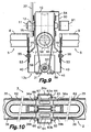
- FIG. 9 shows one of the base bodies 10 of the tracking mechanism 4 connected to the corresponding first supporting profile 13a by means of a pair of auxiliary parts 7.
- the base body 10 comprises first receiver positioning configurations 12 precisely positioned with respect to said supporting shaft 11, for example, in the form of circular projections formed in the wall of the base body 10 around the supporting shaft 11.
- the mentioned auxiliary parts 7 comprise second receiver positioning configurations 15, for example in the form of holes in which the first receiver positioning configurations 12 are tightly inserted.
- respective facing holes through which positioning pins 53 are inserted are formed in the auxiliary parts 7 and in the upright walls 40 of the first supporting profile 13a.
- the second receiver positioning configurations 15 formed in the auxiliary parts 7 are precisely positioned with respect to the second module positioning configurations 14 formed in the supporting profile 13a.
- the auxiliary parts 7 are fixed to the base body 10 and to the upright walls 40 of the first supporting profile 13a by means of respective screws 54, 55, for example, and the first receiver positioning configurations 12 cooperate with the second receiver positioning configurations 15 in order to position each base body 10 in a predetermined operative position in relation to the corresponding supporting profile 13a and thereby assure a predetermined degree of precision for the path of the mobile receiver 2 in relation to said stationary reflector-concentrator 1 guided and driven by the tracking mechanism 4.
- the positioning configurations between the base body 10 and the first supporting profile 13a could alternatively have shapes different to those shown, and that the auxiliary parts 7 could be omitted or replaced with appendages of the base body 10 and/or of the first supporting profile 13a without departing from the scope of the present invention.
- Figure 9 also shows the movement transmission means between the drive shaft 31, which is installed in bearing blocks 56 fixed to the bottom wall 51 of the first supporting profile 13a, and the input shaft 44 of the gear reducer of the base body 10.
- the movement transmission means comprise a driving pulley 57 fixed to the drive shaft 31, a driven pulley 58 fixed to the input shaft 44 and a belt 59 installed around the driving and driven pulleys 57, 58.
- a support 60 is fixed on the base body 10, on which support 60 an angular position detector 61 associated with the supporting shaft 11 is assembled.
- the angular position detector 61 can be used in an electronic control of the drive of the tracking mechanism 4.
- the supporting bodies 10, the components of the movement transmission means, the corresponding drive motor 32 and other related accessories can be installed in each first supporting profile 13a in a prior manufacturing phase and supplied as an assembly to facilitate their quick installation in situ.
- the mobile structure 3 supporting the mobile receiver 2 is formed by a grid made up of longitudinal profiles 33 and transverse profiles 34a, 34b, and the receptor elements 35 are supported at their ends between every two of the transverse profiles 34a, 34b.
- the concentrator-collector device is aimed at using thermal energy of the sun's rays to heat a heat-transfer fluid, such as, for example, water.
- each of the receptor elements 35 comprises a receptor tube 36 through which the mentioned heat-transfer fluid circulates, with an inlet end 36a and an outlet end 36b connected and communicated with a circuit for the heat-transfer fluid.
- each receptor element comprises, as is conventional, a transparent tubular cover 62, for example, of glass, inside which the mentioned receptor tube 36 is arranged.
- the receptor tube 36 of each receptor element 35 is bent such that it has inlet and outlet ends 36a, 36b protruding from one and the same end of the transparent tubular cover 62 of the receptor element 35.
- Several of the transverse profiles 34a of the mobile structure 3 are sections having a closed cross-section forming two parallel ducts which function, respectively, like a supply duct 63a and a return duct 63b in connection with said circuit for the heat-transfer fluid.
- the inlet and outlet ends 36a, 36b of each receptor tube 36 are connected and communicated respectively with said supply and return ducts 63a, 63b formed by one of the transverse profiles 34a.
- each transverse profile 34a forming the supply and return ducts 63a, 63b receives the connection of receptor elements 35 from two opposite sides of the same.
- each of the supply and return ducts 63a, 63b is traversed by a connecting sleeve 64 passed through a pair of aligned holes formed in facing walls of the transverse profile 34a and fixed to the transverse profile 34a, for example, by means of a widened head 65 and a nut 66 coupled to a threaded outer portion thereof.
- the mentioned connecting sleeve 64 is traversed from end to end by a passage having an opening 67 in communication with the corresponding supply or return duct 63a, 63b, and opposite ends of said passage are sized to receive by socket-coupling corresponding inlet or outlet ends 36a, 36b of the receptor tubes 36 of two of the receptor elements 35 located in opposite sides of the transverse profile 34a.
- the connecting sleeves function like supporting members of the receptor elements 32 and like connections for the flow of the heat-transfer fluid.
- the supply and return ducts 63a, 63b are connected to the circuit of the heat-transfer fluid by means of flexible tubes (not shown).
- the inlet and outlet ends 36a, 36b of the receptor tubes 36 can be connected to respective supply and return ducts 63a, 63b formed in two different transverse profiles 34a arranged next to one another.
- the receptor tube 36 of each receptor element 35 is rectilinear and has the inlet and outlet ends 36a, 36b protruding from opposite ends of the transparent tubular cover 62, in which case the inlet and outlet ends 36a, 36b of each receptor tube 36 will be connected to respective supply and return ducts 63a, 63b formed in two different transverse profiles 34a arranged next to opposite ends of the receptor element 35.
- each reflective surface portion 8 of the reflector-concentrator module 5 defines a ruled concave surface having a substantially parabolic cross-section.
- the parabolic cross-section of the reflective surface portion 8 has two side edges B1, B2, a parabola vertex V centered between said side edges B1, B2, a parabola axis E and a parabola focus F coinciding with the mentioned linear focus.
- the tracking mechanism 4 is configured and arranged in order to support and move the mobile structure 3 such that each of the receptor elements 35 of the mobile receiver 2 describes a circular path T which passes through said parabola focus F, and having a center C on said parabola axis E, a lower point P in the lower intersection of the path T with the parabola axis E, and a diameter D slightly greater than a distance FV between the parabola focus F and the mentioned parabola vertex V.
- the ratio of the mentioned diameter D of the circular path T with respect to said distance FV between the parabola focus F and the parabola vertex V is preferably within the range 1 ⁇ D/FV ⁇ 1.10.
- the mentioned side edges B1, B2 of the reflective surface portion 8 are separated from one another by a distance A, and the ratio of said distance A with respect to the diameter D of the circular path T is preferably in the range of 1:0.9 to 1:2.0.
- the center C of the circular path T is at a significant height above the reflective surface portion 8, which would be a drawback if positioning the supporting shaft 11 of the base body 10 aligned with the center C was desired because very high supports anchored in the first transverse profile 13a and very long movement transmission means for transmitting the movement from the drive shaft 31 to the input shaft 44 of the base body 10 would be required.
- the supporting shaft 11 of each base body 10 is shifted downwards and/or towards a side with respect to the center C of any of the circular paths T, preferably close to one of the side edges B1, B2 of the reflective surface portion 8, or more specifically, close to where the side edges B1, B2 of two adjacent reflective surface portions 8 come together.
- each base body 10 is fixedly connected to a pivoting arm 37 the distal end of which is connected by means of a hinge pin 38 to a leg 39 which extends downwards from the mobile structure 3.
- Each pivoting arm 37 has a length L between the supporting shaft 11 and said hinge pin 38, and said length L is equal to the radius of the circular path T, or in other words, equal to half the diameter D of the circular path T.
- the sum of a first normal distance d1 between said lower point P of the circular path T and the supporting shaft 11 and a second normal distance d2 between the hinge pin 38 and a central line L of the receptor element 35 is also equal to the radius of the circular path T, or in other words, equal to the other half of the diameter D of the circular path T.
- the circular path T will always be centered in the center C no matter what the position of the supporting shaft 11. If the supporting shaft 11 was located at a lower level than the lower point P of the circular path T, the first normal distance d1 would have a negative sign.
- FIG 12 shows another alternative embodiment of the solar energy concentrator-collector device of the present invention, in which the receptor elements 35 are, for example, photovoltaic receivers having an essentially planar configuration, which are more sensitive to the direction of the rays collected by the thermal energy receptor elements.
- each of the receptor elements 35 is rotationally supported at its ends such that it can rotate about a longitudinal axis 68, and several of the receptor elements 35 are connected by movement transmission means to a driving pulley 40 centered in the hinge pin 38 and fixedly joined to the pivoting arm 37.
- a driven pulley 69 is assembled which can rotate with respect to a shaft 70 parallel to the longitudinal shafts 68 and located in one and the same plane as the same.
- An arm 71 integral with the driven pulley 69 is hingedly connected to a transmission rod 72, which in turn is hingedly connected with a series of arms 73 integral with the receptor element 35.
- a belt 74 or the like is installed encircling arcs of the driving and driven pulleys 40, 69, such that a rotation of the pivoting arm 37 around the supporting shaft 11 is transmitted to the receptor elements 37 causing a rotation thereof around their respective longitudinal shafts 68.
- This construction can obviously be applied to a concentrator-collector device using thermal energy collecting elements associated with a circuit for a heat-transfer fluid, for example such as those described above in relation to Figures 1 to 10 or other similar ones.
- the concentrator-collector device of the present invention comprises a stationary reflector-concentrator 1 in which the reflective surface portions 8 are located at a higher level with respect to upper edges of the supporting profiles 13a, 13b, 13c, and the base bodies 10 are located in alignment with the confluence of two adjacent reflective surface portions 8, such that there are substantially no impediments along the longitudinal rows of aligned reflective surface portions 8.
- the concentrator-collector device furthermore comprises an automatic cleaning device based on a mechanism configured and arranged for shifting cleaning elements, such as brushes, cloths or the like, along the longitudinal direction of the reflective surfaces in cooperation with a cleaning liquid sprayed, for example, from strategically located nozzles connected to a cleaning liquid circuit.
Landscapes
- Engineering & Computer Science (AREA)
- Physics & Mathematics (AREA)
- Life Sciences & Earth Sciences (AREA)
- Sustainable Development (AREA)
- Sustainable Energy (AREA)
- Thermal Sciences (AREA)
- Chemical & Material Sciences (AREA)
- Combustion & Propulsion (AREA)
- Mechanical Engineering (AREA)
- General Engineering & Computer Science (AREA)
- Photovoltaic Devices (AREA)
Claims (14)
- Un dispositif collecteur concentrateur d'énergie solaire, du genre comportant:un concentrateur réflecteur stationnaire (1) ayant une pluralité de portions à surface réfléchissante concave allongée (8), chacune étant configurée pour réfléchir les rayons de soleil et les concentrer sur un foyer linéaire parallèle à une direction longitudinale, ces portions de surface réfléchissantes (8) étant agencées parallèles les unes à côté des autres et reliées à une structure stationnaire (21);un récepteur mobile (2) ayant une pluralité d'éléments récepteurs allongés (35) agencés parallèles dans le sens de ces foyers linéaires (F) et reliés à une structure mobile (3); etun mécanisme de suivi (4) relié à cette structure stationnaire (21) et à cette structure mobile (3) pour supporter et déplacer la structure mobile (3) sur ce concentrateur réflecteur stationnaire (1) dans une trajectoire de sorte que ces éléments récepteurs (35) suivent la confluence maximale des rayons de soleil réfléchis par les surfaces réfléchissantes lorsque la position relative du soleil change;caractérisé en ce que:chaque portion de surface réfléchissante (8) a sensiblement la forme d'une surface rayée ayant un sommet parabolique (V), un axe de parabolique (E) et un foyer parabolique (F) coïncidant avec ce foyer linéaire, et le mécanisme de suivi (4) est agencé pour supporter y déplacer la structure mobile (3) de sorte que chacun des éléments récepteurs (35) du récepteur mobile (2) décrive une trajectoire circulaire (T) passant à travers ce foyer parabolique (F) et possédant un centre (C) sur cet axe parabolique (E), un point inférieur (P) à l'intersection inférieure avec l'axe parabolique (E) et un diamètre (D) supérieur à la distance (FV) entre le foyer parabolique (F) et ce sommet parabolique (V), dans lequel le ratio de ce diamètre (D) par rapport à cette distance (FV) ce trouve dans la plage de 1<D/FV≤1,10.
- Le dispositif conformément à la revendication 1, caractérisé en ce que la portion de surface réfléchissante (8) possède deux bords latéraux (B1, B2), ce sommet parabolique (V) est centré entre ces bords latéraux (B1, B2) et le ratio d'une distance (A) entre les bords latéraux (B1, B2) de chaque portion de surface réfléchissante (8) par rapport au diamètre (D) de la trajectoire circulaire (T) est dans la plage de 1:0.9 à 1:2.0.
- Le dispositif conformément à la revendication 1, caractérisé en ce que le concentrateur réflecteur stationnaire (1) comporte une pluralité de modules concentrateurs réflecteurs (5) agencés formant une matrice à rangées longitudinales et transversales, chacun de ces modules concentrateurs réflecteurs (5) comportant un châssis (6) auquel est fixé au moins un élément supérieur (18) transportant au moins une portion de surface réfléchissante (8), dans lequel la structure stationnaire (21) est formée par ces châssis (6) des modules concentrateurs réflecteurs (5) et par une pluralité de profils de support (13a, 13b, 13c), où les châssis (6) des modules concentrateurs réflecteurs (5) de chaque rangée sont fixés aux extrémités ou côtés opposés d'au moins deux de ces profils de support (13a, 13b, 13c).
- Le dispositif conformément à la revendication 3, caractérisé en ce que ce mécanisme de suivi (4) comporte au moins trois corps de base (10) fixés à au moins deux des profils de support (13a) et chacun de ces corps de base (10) supporte en rotation au moins un arbre de support (11) sur lequel est assemblé un bras pivotant (37), relié à la structure mobile (3) pour guider les mouvements de la structure mobile (3).
- Le dispositif conformément à la revendication 3 ou 4, caractérisé en ce que cet élément supérieur (18) transportant cette portion de surface réfléchissante (8) de chaque module concentrateur réflecteur (5) est précisément placée dans une position de travail stable prédéterminée par rapport au châssis correspondant (6) et le châssis (6) de chaque module concentrateur réflecteur (5) comporte des premières configurations de positionnement de module (9) coopérant avec des deuxièmes configurations de positionnement de module (14) se trouvant sur ces profils de support (13a, 13b, 13c) pour positionner chaque module concentrateur réflecteur (5) et avec lui, la portion de surface réfléchissante correspondante (8) dans une position de travail prédéterminée par rapport aux profils de support (13a, 13b, 13c).
- Le dispositif conformément à la revendication 5, caractérisé en ce que les profils de support (13a, 13b, 13c) comportent des éléments de fixation (16) associés à ces deuxièmes configurations de positionnement de module (14) et capables d'immobiliser ces premières configurations de positionnement de module (9) par rapport aux deuxièmes configurations de positionnement de module (14).
- Le dispositif conformément à la revendication (6), caractérisé en ce que ces éléments de fixation (16) sont capables d'une action rapide par déformation élastique.
- Le dispositif conformément à la revendication 5, caractérisé en ce que chaque corps de base (10) du mécanisme de suivi (4) comporte des premières configurations de positionnement de récepteur (12) précisément positionnées par rapport à cet arbre de support (11) et les profils de support correspondants (13a) ou les pièces auxiliaires (7) qui y sont fixées, comportent des deuxièmes configurations de positionnement de récepteur (15) précisément positionnées par rapport à ces deuxièmes configurations de positionnement de module (14), ces premières configurations de positionnement de récepteur (12) coopérant avec ces deuxièmes configurations de positionnement de récepteur (15) pour positionner chaque corps de base (10) dans une position de travail prédéterminée par rapport au profil de support correspondant (13a) en assurant ainsi un degré de précision prédéterminé à cette trajectoire du récepteur mobile (2) par rapport à ce concentrateur réflecteur stationnaire (1).
- Le dispositif conformément à la revendication 8, caractérisé en ce que les profils de support (13a, 13b, 13c) sont agencés transversalement dans le sens de ces foyers linéaires (F) et les châssis (6) des modules réflecteurs-concentrateurs (5) de chaque rangée transversale sont fixés à leurs extrémités opposées à deux de ces profils de support (13a, 13b, 13c).
- Le dispositif conformément à la revendication 9, caractérisé en ce que la pluralité de profils de support (13a, 13b, 13c) comportent au moins deux premiers profils de support (13a) et au moins un deuxième profil de support (13b), chacun étant agencé entre deux rangées transversales de modules concentrateurs réflecteurs (5), où chacun de ces premier et deuxième profils de support (13a, 13b) possède une paire de parois verticales se faisant face (40) sur lesquelles se trouvent les deuxièmes configurations de positionnement correspondantes (14), dans lequel chacun de ces premiers profils de support (13a) a la forme d'une rigole ouverte à la partie supérieure où cette paire de parois verticales se faisant face (40) s'étendent depuis les bords latéraux d'une parois de base (41) et où la pluralité des profils de support (13a, 13b, 13c) comportent en plus deux troisièmes profils de support (13c) agencés prés des extrémités extérieures de chacune des rangés transversales d'extrémités de module concentrateur réflecteur (5) où chacun de ces troisièmes profils de support (13c) possèdent une paroi verticale (40) sur laquelle sont formées les deuxièmes configurations de positionnement de module correspondantes (14).
- Le dispositif conformément à la revendication 10, caractérisé en ce que chaque corps de base (10) du mécanisme de suivi (4) est un réducteur de boîte de vitesse dont l'arbre de sortie et l'arbre d'entrée (44) est relié par des moyens de transmission de mouvement à l'arbre de sortie du moteur d'entraînement (32) assemblé sur le premier profil de support correspondant (13a).
- Le dispositif conformément à la revendication 11, caractérisé en ce qu'au moins deux des corps de base (10) du mécanisme de suivi (4) sont installés sur un et même premier profil de support (13a) et leurs arbres de d'entrée respectifs (44) sont reliés par des moyens de transmission de mouvement respectifs à un seul arbre d'entraînement (31) installé le long du premier profil de support (13a) et couplé à l'arbre de sortie d'un seul moteur d'entraînement (32) assemblé sur le premier profil de support (13a).
- Le dispositif conformément à la revendication 12, caractérisé en ce que l'arbre de support (11) de chaque corps de base (10) est parallèle à la direction longitudinale et est relié fixe à une première extrémité d'un bras pivotant (37) qui possède une deuxième extrémité reliée par un axe d'articulation (38) à une patte correspondante (39) s'étendant vers le bas depuis la structure mobile (3), la structure stationnaire (21), ces bras pivotants (37) et la structure mobile (3) fonctionnant comme un parallélogramme articulé pour guider le mouvement de tous les éléments récepteurs (35) du récepteur mobile (2) ensemble par rapport à leurs surfaces réfléchissantes respectives le long d'une trajectoire circulaire (T), dans laquelle chaque bras pivotant (37) a un tronçon (L) entre l'arbre de support (11) et cet axe d'articulation (38) qui est égal à la moitié de ce diamètre (D) de la trajectoire circulaire (T) et la somme d'une première distance normale (d1) entre ce point inférieur (P) de la trajectoire circulaire (T) et l'arbre de support (11) et une deuxième distance normale (d2) entre l'axe d'articulation (38) et une ligne centrale (L) de l'élément récepteur (35) est égale à cette moitié du diamètre (D) de la trajectoire circulaire (T) et dans lequel l'arbre de support (11) de chaque corps de base (10) est dévié vers le bas et/ou vers un coté par rapport au centre (C) d'une quelconque des trajectoires circulaires (T).
- Le dispositif conformément à la revendication 1, caractérisé en ce que la structure mobile (3), comporte une pluralité de profils longitudinaux (33) et de profils transversaux (34a, 34b), reliés entre eux formant une grille et ces éléments récepteurs (35) sont supportés à leurs extrémités entre chaque deux de ces profils transversaux (34a, 34b) dans lequel chacun de ces éléments récepteurs (35) comporte au moins un tube récepteur (36) pour un fluide caloporteur, ayant une extrémité d'entrée (36a) et une extrémité de sortie (36b) reliées et communiquées avec un circuit pour ce fluide caloporteur et dans lequel au moins un de ces profils transversaux (34a) de la structure mobile (3) est un profil ayant une coupe transversale fermée formant un conduit d'approvisionnement (63a) ou un conduit de retour (63b) de ce circuit pour le fluide caloporteur et au moins une de ces extrémités d'entrée et de sortie (36a, 36b) de chaque tube récepteur (36) est reliée et communiquée avec un conduit respectif de ces conduits d'approvisionnement et de retour (63a, 63b) formé par le profil transversal (34a).
Applications Claiming Priority (2)
| Application Number | Priority Date | Filing Date | Title |
|---|---|---|---|
| ES200703464A ES2326353B1 (es) | 2007-12-28 | 2007-12-28 | Dispositivo concentrador-captador de energia solar. |
| PCT/ES2008/000801 WO2009083626A1 (fr) | 2007-12-28 | 2008-12-26 | Dispositif concentrateur-capteur d'énergie solaire |
Publications (3)
| Publication Number | Publication Date |
|---|---|
| EP2233859A1 EP2233859A1 (fr) | 2010-09-29 |
| EP2233859A4 EP2233859A4 (fr) | 2013-05-01 |
| EP2233859B1 true EP2233859B1 (fr) | 2014-05-07 |
Family
ID=40823800
Family Applications (1)
| Application Number | Title | Priority Date | Filing Date |
|---|---|---|---|
| EP08868504.5A Not-in-force EP2233859B1 (fr) | 2007-12-28 | 2008-12-26 | Dispositif concentrateur-capteur d'énergie solaire |
Country Status (5)
| Country | Link |
|---|---|
| US (1) | US20110168160A1 (fr) |
| EP (1) | EP2233859B1 (fr) |
| CN (1) | CN102239369A (fr) |
| ES (1) | ES2326353B1 (fr) |
| WO (1) | WO2009083626A1 (fr) |
Families Citing this family (12)
| Publication number | Priority date | Publication date | Assignee | Title |
|---|---|---|---|---|
| AU2009334144B2 (en) * | 2008-11-17 | 2012-12-13 | Tm Tech Co., Ltd | Light Sensor Holder for Tracking Sunlight |
| EP2639526A1 (fr) * | 2012-03-13 | 2013-09-18 | Areva Solar, Inc | Concentrateur solaire pour un collecteur d'énergie solaire et procédé de réglage du concentrateur solaire |
| US10094595B1 (en) * | 2012-05-10 | 2018-10-09 | Lockheed Martin Corporation | Solar heat collector |
| US9249990B2 (en) * | 2012-07-19 | 2016-02-02 | The Florida State University Research Foundation, Inc. | Multiple parabolic trough solar collector having a focus-tracking pipe array |
| SE541893C2 (sv) * | 2013-02-24 | 2020-01-02 | Lennart Carlsen | Stativ för solpaneler |
| US20160161151A1 (en) * | 2013-07-11 | 2016-06-09 | Solar Fire Concentration Oy | Method and arrangement for utilizing solar energy, method and system for implementing and designing an arrangement for utilizing solar energy and computer program product |
| US9842954B1 (en) | 2013-08-06 | 2017-12-12 | William Andrew Lorenz | Radiation collection apparatus with flexible stationary mirror |
| US9239444B2 (en) * | 2013-09-23 | 2016-01-19 | Austin R Gurley | Incident and reflective mirror array focusing by kinematic function control |
| CN104197544A (zh) * | 2014-07-25 | 2014-12-10 | 上海建科建筑节能技术股份有限公司 | 模块化太阳能集热器 |
| IT201600129373A1 (it) * | 2016-12-21 | 2018-06-21 | Sun Gen Srl | Concentratore solare |
| CN108459390B (zh) * | 2018-04-19 | 2020-05-01 | 亚太兆业有限公司 | 聚能装置 |
| CN110057114B (zh) * | 2019-04-01 | 2021-06-25 | 浙江中控太阳能技术有限公司 | 反射面积可调的光伏光热耦合定日镜镜面结构及定日镜 |
Family Cites Families (14)
| Publication number | Priority date | Publication date | Assignee | Title |
|---|---|---|---|---|
| US3868823A (en) * | 1972-04-06 | 1975-03-04 | Gulf Oil Corp | Concentrator, method, and system for utilizing radiant energy |
| US4602853A (en) * | 1976-11-30 | 1986-07-29 | Aai Corporation | Solar energy concentrating and collecting arrangement |
| CA1113813A (fr) | 1976-11-30 | 1981-12-08 | Irwin R. Barr | Capteur/reflecteur solaire |
| US4205659A (en) * | 1977-08-08 | 1980-06-03 | Beam Engineering, Inc. | Solar energy collector |
| AU525891B2 (en) * | 1977-10-20 | 1982-12-09 | Benlloch Llorach Alfredo | Improvements in devices to exploit solar energy |
| US4217884A (en) * | 1978-04-27 | 1980-08-19 | Strong John D | Collection and utilization of solar energy |
| IL58249A0 (en) * | 1978-09-22 | 1979-12-30 | Benlloch Llorach Alfredo | Improvements in devices to exploit solar energy |
| US4324947A (en) * | 1979-05-16 | 1982-04-13 | Dumbeck Robert F | Solar energy collector system |
| SE449784B (sv) * | 1985-09-13 | 1987-05-18 | Scandinavian Solar Ab | Festanordning |
| US5542409A (en) * | 1995-01-06 | 1996-08-06 | Sampayo; Eduardo A. | Solar concentrator system |
| JPH1026423A (ja) | 1996-07-08 | 1998-01-27 | Junichi Miura | とい型凹面鏡固定型ソーラーシステム |
| WO1999020953A1 (fr) * | 1997-10-20 | 1999-04-29 | Manousos Pattakos | Appareil permettant de recueillir le rayonnement solaire |
| BE1011529A3 (nl) * | 1997-11-04 | 1999-10-05 | Solel Consumer Naamloze Vennoo | Inrichting voor het reflecteren van zonnestraling. |
| US8132409B2 (en) * | 2007-05-08 | 2012-03-13 | Solar Turbine Group, International | Solar collection and conversion system and methods and apparatus for control thereof |
-
2007
- 2007-12-28 ES ES200703464A patent/ES2326353B1/es not_active Expired - Fee Related
-
2008
- 2008-12-26 CN CN2008801275663A patent/CN102239369A/zh active Pending
- 2008-12-26 WO PCT/ES2008/000801 patent/WO2009083626A1/fr not_active Ceased
- 2008-12-26 EP EP08868504.5A patent/EP2233859B1/fr not_active Not-in-force
- 2008-12-26 US US12/810,927 patent/US20110168160A1/en not_active Abandoned
Also Published As
| Publication number | Publication date |
|---|---|
| US20110168160A1 (en) | 2011-07-14 |
| EP2233859A1 (fr) | 2010-09-29 |
| EP2233859A4 (fr) | 2013-05-01 |
| ES2326353B1 (es) | 2010-07-13 |
| ES2326353A1 (es) | 2009-10-07 |
| WO2009083626A1 (fr) | 2009-07-09 |
| CN102239369A (zh) | 2011-11-09 |
Similar Documents
| Publication | Publication Date | Title |
|---|---|---|
| EP2233859B1 (fr) | Dispositif concentrateur-capteur d'énergie solaire | |
| CN1047836C (zh) | 辐射能收集装置 | |
| US9568215B2 (en) | Solar central receiver system employing common positioning mechanism for heliostats | |
| US6485152B2 (en) | Matrix solar dish | |
| JP4541395B2 (ja) | 太陽光追尾センサの方位設定方法 | |
| US20100205963A1 (en) | Concentrated solar power generation system with distributed generation | |
| US20100206303A1 (en) | Solar Concentrator Truss Assemblies | |
| WO2009023063A2 (fr) | Récepteur d'énergie solaire doté d'une ouverture optiquement inclinée | |
| US20160003496A1 (en) | Modular solar field | |
| CN103165699A (zh) | 塔式太阳能定日镜锥齿轮被动自动追日支架 | |
| US8474445B2 (en) | Concentrating solar energy device | |
| CN202614969U (zh) | 一种线性菲涅尔太阳能可调曲率反射镜装置 | |
| Li et al. | Effects of receiver parameters on the optical efficiency of a fixed linear-focus Fresnel lens solar system with sliding adjustment | |
| EP2573485A1 (fr) | Dispositif de concentration de rayonnement solaire, équipé de miroirs et d'un récepteur longitudinaux | |
| JPS6014272B2 (ja) | 太陽エネルギ−の集中採取のための複数反射体から成る太陽エネルギ−反射装置 | |
| WO2014015012A1 (fr) | Collecteur solaire à creux paraboliques multiples ayant un réseau de tuyaux de suivi de foyer | |
| CN112378094A (zh) | 透射型太阳能聚光集热系统 | |
| US4335707A (en) | Solar energy collector and energy storage cell | |
| CN212511880U (zh) | 一种阳光反射传感器及应用其的聚光装置 | |
| CN102426460A (zh) | 线性菲涅尔太阳能跟踪驱动控制装置 | |
| KR20030027528A (ko) | 비대칭 반사면을 갖는 태양열 집속집열기 | |
| EP3403031B1 (fr) | Collecteur de rayonnement statique optimisé | |
| CN223883836U (zh) | 一种二次聚焦的聚光镜 | |
| KR20110118883A (ko) | 태양 위치 추적 및 집광형 태양광 보일러 | |
| Martínez et al. | Design improvements and evaluation of the new CCStar collector |
Legal Events
| Date | Code | Title | Description |
|---|---|---|---|
| PUAI | Public reference made under article 153(3) epc to a published international application that has entered the european phase |
Free format text: ORIGINAL CODE: 0009012 |
|
| 17P | Request for examination filed |
Effective date: 20100702 |
|
| AK | Designated contracting states |
Kind code of ref document: A1 Designated state(s): AT BE BG CH CY CZ DE DK EE ES FI FR GB GR HR HU IE IS IT LI LT LU LV MC MT NL NO PL PT RO SE SI SK TR |
|
| AX | Request for extension of the european patent |
Extension state: AL BA MK RS |
|
| DAX | Request for extension of the european patent (deleted) | ||
| A4 | Supplementary search report drawn up and despatched |
Effective date: 20130405 |
|
| RIC1 | Information provided on ipc code assigned before grant |
Ipc: F24J 2/52 20060101ALI20130328BHEP Ipc: F24J 2/14 20060101AFI20130328BHEP Ipc: F24J 2/54 20060101ALI20130328BHEP Ipc: F24J 2/10 20060101ALI20130328BHEP |
|
| GRAP | Despatch of communication of intention to grant a patent |
Free format text: ORIGINAL CODE: EPIDOSNIGR1 |
|
| INTG | Intention to grant announced |
Effective date: 20131216 |
|
| GRAS | Grant fee paid |
Free format text: ORIGINAL CODE: EPIDOSNIGR3 |
|
| GRAA | (expected) grant |
Free format text: ORIGINAL CODE: 0009210 |
|
| AK | Designated contracting states |
Kind code of ref document: B1 Designated state(s): AT BE BG CH CY CZ DE DK EE ES FI FR GB GR HR HU IE IS IT LI LT LU LV MC MT NL NO PL PT RO SE SI SK TR |
|
| REG | Reference to a national code |
Ref country code: GB Ref legal event code: FG4D |
|
| REG | Reference to a national code |
Ref country code: AT Ref legal event code: REF Ref document number: 667000 Country of ref document: AT Kind code of ref document: T Effective date: 20140515 |
|
| REG | Reference to a national code |
Ref country code: IE Ref legal event code: FG4D |
|
| REG | Reference to a national code |
Ref country code: DE Ref legal event code: R096 Ref document number: 602008032180 Country of ref document: DE Effective date: 20140626 |
|
| REG | Reference to a national code |
Ref country code: CH Ref legal event code: NV Representative=s name: BOVARD AG, CH Ref country code: AT Ref legal event code: MK05 Ref document number: 667000 Country of ref document: AT Kind code of ref document: T Effective date: 20140507 |
|
| REG | Reference to a national code |
Ref country code: NL Ref legal event code: VDEP Effective date: 20140507 |
|
| REG | Reference to a national code |
Ref country code: LT Ref legal event code: MG4D |
|
| PG25 | Lapsed in a contracting state [announced via postgrant information from national office to epo] |
Ref country code: GR Free format text: LAPSE BECAUSE OF FAILURE TO SUBMIT A TRANSLATION OF THE DESCRIPTION OR TO PAY THE FEE WITHIN THE PRESCRIBED TIME-LIMIT Effective date: 20140808 Ref country code: LT Free format text: LAPSE BECAUSE OF FAILURE TO SUBMIT A TRANSLATION OF THE DESCRIPTION OR TO PAY THE FEE WITHIN THE PRESCRIBED TIME-LIMIT Effective date: 20140507 Ref country code: IS Free format text: LAPSE BECAUSE OF FAILURE TO SUBMIT A TRANSLATION OF THE DESCRIPTION OR TO PAY THE FEE WITHIN THE PRESCRIBED TIME-LIMIT Effective date: 20140907 Ref country code: NO Free format text: LAPSE BECAUSE OF FAILURE TO SUBMIT A TRANSLATION OF THE DESCRIPTION OR TO PAY THE FEE WITHIN THE PRESCRIBED TIME-LIMIT Effective date: 20140807 Ref country code: CY Free format text: LAPSE BECAUSE OF FAILURE TO SUBMIT A TRANSLATION OF THE DESCRIPTION OR TO PAY THE FEE WITHIN THE PRESCRIBED TIME-LIMIT Effective date: 20140507 Ref country code: FI Free format text: LAPSE BECAUSE OF FAILURE TO SUBMIT A TRANSLATION OF THE DESCRIPTION OR TO PAY THE FEE WITHIN THE PRESCRIBED TIME-LIMIT Effective date: 20140507 |
|
| PG25 | Lapsed in a contracting state [announced via postgrant information from national office to epo] |
Ref country code: SE Free format text: LAPSE BECAUSE OF FAILURE TO SUBMIT A TRANSLATION OF THE DESCRIPTION OR TO PAY THE FEE WITHIN THE PRESCRIBED TIME-LIMIT Effective date: 20140507 Ref country code: PL Free format text: LAPSE BECAUSE OF FAILURE TO SUBMIT A TRANSLATION OF THE DESCRIPTION OR TO PAY THE FEE WITHIN THE PRESCRIBED TIME-LIMIT Effective date: 20140507 Ref country code: AT Free format text: LAPSE BECAUSE OF FAILURE TO SUBMIT A TRANSLATION OF THE DESCRIPTION OR TO PAY THE FEE WITHIN THE PRESCRIBED TIME-LIMIT Effective date: 20140507 Ref country code: HR Free format text: LAPSE BECAUSE OF FAILURE TO SUBMIT A TRANSLATION OF THE DESCRIPTION OR TO PAY THE FEE WITHIN THE PRESCRIBED TIME-LIMIT Effective date: 20140507 Ref country code: LV Free format text: LAPSE BECAUSE OF FAILURE TO SUBMIT A TRANSLATION OF THE DESCRIPTION OR TO PAY THE FEE WITHIN THE PRESCRIBED TIME-LIMIT Effective date: 20140507 Ref country code: ES Free format text: LAPSE BECAUSE OF FAILURE TO SUBMIT A TRANSLATION OF THE DESCRIPTION OR TO PAY THE FEE WITHIN THE PRESCRIBED TIME-LIMIT Effective date: 20140507 |
|
| PG25 | Lapsed in a contracting state [announced via postgrant information from national office to epo] |
Ref country code: PT Free format text: LAPSE BECAUSE OF FAILURE TO SUBMIT A TRANSLATION OF THE DESCRIPTION OR TO PAY THE FEE WITHIN THE PRESCRIBED TIME-LIMIT Effective date: 20140908 |
|
| PG25 | Lapsed in a contracting state [announced via postgrant information from national office to epo] |
Ref country code: DK Free format text: LAPSE BECAUSE OF FAILURE TO SUBMIT A TRANSLATION OF THE DESCRIPTION OR TO PAY THE FEE WITHIN THE PRESCRIBED TIME-LIMIT Effective date: 20140507 Ref country code: EE Free format text: LAPSE BECAUSE OF FAILURE TO SUBMIT A TRANSLATION OF THE DESCRIPTION OR TO PAY THE FEE WITHIN THE PRESCRIBED TIME-LIMIT Effective date: 20140507 Ref country code: SK Free format text: LAPSE BECAUSE OF FAILURE TO SUBMIT A TRANSLATION OF THE DESCRIPTION OR TO PAY THE FEE WITHIN THE PRESCRIBED TIME-LIMIT Effective date: 20140507 Ref country code: RO Free format text: LAPSE BECAUSE OF FAILURE TO SUBMIT A TRANSLATION OF THE DESCRIPTION OR TO PAY THE FEE WITHIN THE PRESCRIBED TIME-LIMIT Effective date: 20140507 Ref country code: BE Free format text: LAPSE BECAUSE OF FAILURE TO SUBMIT A TRANSLATION OF THE DESCRIPTION OR TO PAY THE FEE WITHIN THE PRESCRIBED TIME-LIMIT Effective date: 20140507 Ref country code: CZ Free format text: LAPSE BECAUSE OF FAILURE TO SUBMIT A TRANSLATION OF THE DESCRIPTION OR TO PAY THE FEE WITHIN THE PRESCRIBED TIME-LIMIT Effective date: 20140507 |
|
| REG | Reference to a national code |
Ref country code: DE Ref legal event code: R097 Ref document number: 602008032180 Country of ref document: DE |
|
| PG25 | Lapsed in a contracting state [announced via postgrant information from national office to epo] |
Ref country code: NL Free format text: LAPSE BECAUSE OF FAILURE TO SUBMIT A TRANSLATION OF THE DESCRIPTION OR TO PAY THE FEE WITHIN THE PRESCRIBED TIME-LIMIT Effective date: 20140507 |
|
| PLBE | No opposition filed within time limit |
Free format text: ORIGINAL CODE: 0009261 |
|
| STAA | Information on the status of an ep patent application or granted ep patent |
Free format text: STATUS: NO OPPOSITION FILED WITHIN TIME LIMIT |
|
| 26N | No opposition filed |
Effective date: 20150210 |
|
| PG25 | Lapsed in a contracting state [announced via postgrant information from national office to epo] |
Ref country code: IT Free format text: LAPSE BECAUSE OF FAILURE TO SUBMIT A TRANSLATION OF THE DESCRIPTION OR TO PAY THE FEE WITHIN THE PRESCRIBED TIME-LIMIT Effective date: 20140507 |
|
| REG | Reference to a national code |
Ref country code: DE Ref legal event code: R097 Ref document number: 602008032180 Country of ref document: DE Effective date: 20150210 |
|
| REG | Reference to a national code |
Ref country code: DE Ref legal event code: R119 Ref document number: 602008032180 Country of ref document: DE |
|
| PG25 | Lapsed in a contracting state [announced via postgrant information from national office to epo] |
Ref country code: LU Free format text: LAPSE BECAUSE OF FAILURE TO SUBMIT A TRANSLATION OF THE DESCRIPTION OR TO PAY THE FEE WITHIN THE PRESCRIBED TIME-LIMIT Effective date: 20141226 Ref country code: SI Free format text: LAPSE BECAUSE OF FAILURE TO SUBMIT A TRANSLATION OF THE DESCRIPTION OR TO PAY THE FEE WITHIN THE PRESCRIBED TIME-LIMIT Effective date: 20140507 |
|
| GBPC | Gb: european patent ceased through non-payment of renewal fee |
Effective date: 20141226 |
|
| REG | Reference to a national code |
Ref country code: IE Ref legal event code: MM4A |
|
| REG | Reference to a national code |
Ref country code: FR Ref legal event code: ST Effective date: 20150831 |
|
| PG25 | Lapsed in a contracting state [announced via postgrant information from national office to epo] |
Ref country code: IE Free format text: LAPSE BECAUSE OF NON-PAYMENT OF DUE FEES Effective date: 20141226 Ref country code: GB Free format text: LAPSE BECAUSE OF NON-PAYMENT OF DUE FEES Effective date: 20141226 Ref country code: DE Free format text: LAPSE BECAUSE OF NON-PAYMENT OF DUE FEES Effective date: 20150701 |
|
| PG25 | Lapsed in a contracting state [announced via postgrant information from national office to epo] |
Ref country code: FR Free format text: LAPSE BECAUSE OF NON-PAYMENT OF DUE FEES Effective date: 20141231 |
|
| PGFP | Annual fee paid to national office [announced via postgrant information from national office to epo] |
Ref country code: CH Payment date: 20160226 Year of fee payment: 8 |
|
| PG25 | Lapsed in a contracting state [announced via postgrant information from national office to epo] |
Ref country code: BG Free format text: LAPSE BECAUSE OF FAILURE TO SUBMIT A TRANSLATION OF THE DESCRIPTION OR TO PAY THE FEE WITHIN THE PRESCRIBED TIME-LIMIT Effective date: 20140507 Ref country code: MC Free format text: LAPSE BECAUSE OF FAILURE TO SUBMIT A TRANSLATION OF THE DESCRIPTION OR TO PAY THE FEE WITHIN THE PRESCRIBED TIME-LIMIT Effective date: 20140507 |
|
| PG25 | Lapsed in a contracting state [announced via postgrant information from national office to epo] |
Ref country code: HU Free format text: LAPSE BECAUSE OF FAILURE TO SUBMIT A TRANSLATION OF THE DESCRIPTION OR TO PAY THE FEE WITHIN THE PRESCRIBED TIME-LIMIT; INVALID AB INITIO Effective date: 20081226 Ref country code: TR Free format text: LAPSE BECAUSE OF FAILURE TO SUBMIT A TRANSLATION OF THE DESCRIPTION OR TO PAY THE FEE WITHIN THE PRESCRIBED TIME-LIMIT Effective date: 20140507 Ref country code: MT Free format text: LAPSE BECAUSE OF FAILURE TO SUBMIT A TRANSLATION OF THE DESCRIPTION OR TO PAY THE FEE WITHIN THE PRESCRIBED TIME-LIMIT Effective date: 20140507 |
|
| REG | Reference to a national code |
Ref country code: CH Ref legal event code: PL |
|
| PG25 | Lapsed in a contracting state [announced via postgrant information from national office to epo] |
Ref country code: CH Free format text: LAPSE BECAUSE OF NON-PAYMENT OF DUE FEES Effective date: 20161231 Ref country code: LI Free format text: LAPSE BECAUSE OF NON-PAYMENT OF DUE FEES Effective date: 20161231 |