EP2233998A2 - Soupape de réglage de pression - Google Patents
Soupape de réglage de pression Download PDFInfo
- Publication number
- EP2233998A2 EP2233998A2 EP10002259A EP10002259A EP2233998A2 EP 2233998 A2 EP2233998 A2 EP 2233998A2 EP 10002259 A EP10002259 A EP 10002259A EP 10002259 A EP10002259 A EP 10002259A EP 2233998 A2 EP2233998 A2 EP 2233998A2
- Authority
- EP
- European Patent Office
- Prior art keywords
- channel
- pressure
- pressure control
- control valve
- valve
- Prior art date
- Legal status (The legal status is an assumption and is not a legal conclusion. Google has not performed a legal analysis and makes no representation as to the accuracy of the status listed.)
- Granted
Links
Images
Classifications
-
- G—PHYSICS
- G05—CONTROLLING; REGULATING
- G05D—SYSTEMS FOR CONTROLLING OR REGULATING NON-ELECTRIC VARIABLES
- G05D16/00—Control of fluid pressure
- G05D16/04—Control of fluid pressure without auxiliary power
- G05D16/06—Control of fluid pressure without auxiliary power the sensing element being a flexible membrane, yielding to pressure, e.g. diaphragm, bellows, capsule
- G05D16/063—Control of fluid pressure without auxiliary power the sensing element being a flexible membrane, yielding to pressure, e.g. diaphragm, bellows, capsule the sensing element being a membrane
- G05D16/0644—Control of fluid pressure without auxiliary power the sensing element being a flexible membrane, yielding to pressure, e.g. diaphragm, bellows, capsule the sensing element being a membrane the membrane acting directly on the obturator
- G05D16/0663—Control of fluid pressure without auxiliary power the sensing element being a flexible membrane, yielding to pressure, e.g. diaphragm, bellows, capsule the sensing element being a membrane the membrane acting directly on the obturator using a spring-loaded membrane with a spring-loaded slideable obturator
-
- G—PHYSICS
- G05—CONTROLLING; REGULATING
- G05D—SYSTEMS FOR CONTROLLING OR REGULATING NON-ELECTRIC VARIABLES
- G05D16/00—Control of fluid pressure
- G05D16/02—Modifications to reduce the effects of instability, e.g. due to vibrations, friction, abnormal temperature, overloading or imbalance
Definitions
- the invention relates to a pressure regulating valve, having a primary channel which can be acted upon by a primary pressure, and also having a secondary channel enabling the tapping of a regulated secondary pressure, and having a valve member controlling the pressure flow between the primary channel and the secondary channel, the position of which being predetermined by a control member interacting with it. which forms a movable wall section of a control chamber in fluid communication with the secondary channel and is acted upon by a secondary pressure default force.
- Pressure regulating valves are used, inter alia, in connection with compressed air processing in compressed air networks and serve to keep the secondary pressure, which can be tapped at the secondary duct as working pressure, largely constant, independent of pressure fluctuations.
- Optional secondary venting measures make it possible to reduce the secondary pressure in the secondary duct when the secondary pressure increases due to the operation of the connected consumer.
- One from the DE 100 02 752 C1 Known pressure control valve of the type mentioned has a pressure flow between a primary channel and a secondary channel predetermining valve member, the position of which is predetermined by a motion-coupled with him control member, on the one hand of a on the other hand acted upon by the secondary pressure preset by spring means and on the other hand by the secondary pressure prevailing in the secondary channel.
- the control member forms a movable wall portion of a control chamber, which communicates with the secondary channel by means of a single, constantly open connection channel.
- the control chamber is separated by a partition wall from the secondary channel, which is penetrated by a driving coupling between the control member and the valve member accomplishing pestle.
- the plunger is sealed with respect to the partition by a sealing ring surrounding it.
- the control engineering design of the known pressure control valve is very problematic, especially for large flows to be controlled.
- the flow cross-section of the connecting channel should be as large as possible.
- a large flow cross-section has the disadvantage that the combined control member and valve member control device is very easily excited to vigorous swing when in another operating situation, the fluid consumption at the output of the secondary channel increases and the secondary pressure therefore drops rapidly.
- this tendency to oscillate can be mechanically counteracted by, inter alia, the sealing of the seal relative to the partition sealing ring is mounted with a relatively large radial bias and thus a frictional force is built up, which leads to a slowing down of the movements of the control member.
- this measure leads to increased wear and a pronounced hysteresis in the characteristic of the pressure control valve.
- a gas pressure regulator is already known in which a throttled connection channel is provided for damping oscillations of the outlet pressure between the outlet channel and a lower diaphragm chamber delimited by a regulator diaphragm.
- a valve which can open in fluctuations in the outlet pressure in one direction, a connection connecting this connection channel can be established.
- the present invention has set itself the goal of proposing measures to counteract the vibration and overshoot problem.
- Such a trained pressure control valve can be relatively easily designed so that it does not tend to swing or so-called overshoot. Also, there is no deliberately increased friction to dampen the movement behavior of the control member, so that the hysteresis of the regulator characteristic is very low, and also the wear can be reduced. These advantages also apply to a design for high maximum flow rates. If the secondary-side fluid consumption drops, the resulting secondary pressure can open the check valve and cause a corresponding increase in pressure in the control chamber with no or only minimal delay, so that the control member can react immediately to the secondary-side pressure change. An overshoot can therefore no longer occur.
- the two connection channels can open separately into the secondary channel. Preferably, however, they open into the secondary channel via a common tap channel.
- the latter allows the advantageous measure, the tap opening spaced from the channel wall and in particular to place cross-sectionally in the secondary channel, specifically aligned in the direction of the secondary terminal, so that adverse flow influences are advantageously avoided.
- the common tap opening is located at a distance from the channel wall of the secondary channel and faces the secondary connection, the controller characteristic curve has been positively influenced and the control behavior is less dependent on the cross section of the secondary connection.
- the latter has the advantage that the pressure regulator can be operated on the secondary side without seriously influencing the control behavior with different nominal diameters, which offers a high flexibility in the application of the pressure regulator.
- the check valve has expediently via a spring-loaded in its closed position biased shut-off.
- the insertion of a holding sleeve into a wall of the pressure regulating valve is recommended, wherein the cavity passing through the holding sleeve can form a longitudinal section of the first connecting channel.
- the second connecting channel can be conveniently referred to as throttle channel.
- throttle channel can be conveniently referred to as throttle channel.
- the flow cross-section of the second connecting channel can be used in the wall of the pressure control valve is preferably a sleeve-shaped, working in the manner of an orifice throttle body.
- a sealing ring can prevent fluid entering the secondary channel at high pressure from undesirably passing into the control chamber through a gap existing between the plunger and the partition wall. Due to the measures according to the invention, however, the radial bias of the sealing ring can be very low, so that the mobility of the plunger and consequently of the cooperating with these control member is hardly affected.
- a secondary venting valve formed jointly by the valve member and the control member is expediently provided. It controls a vent passing through the control member and communicating with the atmosphere. If the control member deflected due to an increasing secondary pressure in the sense of increasing the volume of the control chamber, it can lift off the valve member, so that a connection between the secondary channel and the venting channel is released.
- the secondary pressure default force is in particular variably adjustable, preferably manually, if necessary, but also by motor.
- the secondary pressure biasing force is supplied by a biased spring means, wherein means may be provided to vary the bias for the purpose of varying the secondary pressure biasing force.
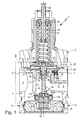
- the generally designated by reference numeral 1 pressure control valve has a housing 2 with a housing main body 3, in which run as a primary channel 4 and as a secondary channel 5 designated fluid channels.
- the primary channel 4 opens out via a designated as primary port 6 opening to a first outer surface 8 of the housing 2, the secondary channel 5 via a secondary terminal 7 designated opening to a second outer surface 9 of the housing 2.
- the two outer surfaces 8, 9 can be arbitrarily oriented , lie in the embodiment, however, on opposite sides.
- pressure medium can be fed in via the primary connection 6 under a primary pressure.
- pressure medium can be fed in via the primary connection 6 under a primary pressure.
- the secondary terminal 7 can be tapped under a secondary pressure pressure medium and forward to one or more consumers.
- the secondary pressure is usually lower than the primary pressure and can be given in height by the pressure control valve 1 as needed.
- the pressure regulating valve 1 is operated with a gaseous medium, in particular compressed air.
- the overflow opening 12 is framed by a valve seat 13 facing the primary duct 4, which faces a closure portion 14a, for example of a plate-shaped design, of a valve member 14.
- Housing bottom 15 supporting spring means 16 act on the valve member 14 in the direction of a valve seat 13 under sealing applied closed position.
- valve member 14 By a force F S acting on it, the valve member 14 can be lifted at different levels from the valve seat 13 to release a more or less large cross-section of the overflow 12, through which a flow of the overflow from the primary channel 4 in the secondary channel 5 pressure medium is predetermined.
- the flow or the flow rate is the greater, the further the valve member 14 is lifted from the valve seat 13.
- the actuating force F S can be exerted by a control member 17 on the valve member 14.
- the control member 17 defines a movable in the same direction as the valve member 14 wall portion 18 which defines a control chamber 22 together with wall portions of the housing 2 within the same.
- the movable wall portion 18 is formed in the embodiment of a substantially disc-shaped, elastically deformable diaphragm 23 which is sealed with its outer edge region 24 secured to the housing 2 and with its central portion of an assembly consisting of a rigid pressure plate 25 and a thereto coaxial plunger 26 is attached.
- the pressure plate 25 and the plunger 26 are firmly connected to each other and also belong to the according to double arrow 27 movable control member 17th
- the plunger 26 penetrates slidably and with sealing a secondary channel 5 of the control chamber 22 separating partition 28, which is a wall portion of the housing 2, in particular of the housing main body 3 acts.
- the seal is effected by a sealing ring 32 which is held in an annular groove formed in the lateral surface of the plunger 26 and slidably rests on the peripheral surface of a penetrated by the plunger 26 opening 33 of the partition 28.
- the plunger 26 terminates freely within the secondary channel 5. With its local end portion 34 it acts on a protruding from the opposite side into the secondary channel 5 actuating projection 35 of the valve member 14, which protrudes from the closure portion 14 a. Plunger 26 and actuating projection 35 are so loosely against each other that they can transmit only pressing forces on each other.
- a coaxially passing through the control member 17 including the plunger 26 venting channel 38 opens at one end outside the control chamber 22 to the atmosphere and has its opposite channel mouth in the region of the end portion 34 oriented in the axial direction of the movement 27, wherein it is arranged by a further valve seat on the plunger 26 37th is framed, on which the valve member 14 with its actuating projection 35 abuts the front side.
- the venting channel 38 is separated from the secondary channel 5.
- the channel mouth of the ventilation channel 38 framed by the second valve seat 37 is exposed and establishes a connection of the secondary channel 5 to the atmosphere.
- a connection channel arrangement establishes a fluidic connection between the secondary channel 5 and the control chamber 22.
- the secondary pressure prevailing in the secondary channel 5 can also be present in the control chamber 22 and act on the control member 17 via the movable wall portion 18 with an actuating force F B opposite the force Fs.
- a secondary pressure-default force F P Opposite to the actuating force F B acts on the control member 17, a secondary pressure-default force F P.
- the secondary pressure preset force F P is supplied by a spring mechanism 43 accommodated in the housing 2 outside the control chamber 22, which is supported at one end on the pressure plate 25 and at the other end by an actuation plate 44 supporting the housing 2.
- the secondary pressure default force F P can also be provided elsewhere, for example by a fluid pressure.
- the secondary pressure specification force F P depends on the set bias of the spring device 43.
- This bias voltage can be varied by adjusting the Beauftschungstellers 44.
- the Beauftschungsteller 44 sits on a rotatable threaded spindle 45 and at the same time with respect to the housing 2 is secured against rotation, so that a rotation of the threaded spindle 45 has a linear adjustment of the Beaufscherungstellers 44 result.
- the spring device 43 is thereby compressed or relieved.
- valve member 14 On the valve member 14 then acts in the opening sense, a force Fs, if the secondary pressure-default force F P is greater than the via the connecting channel arrangement 42 derived from the currently prevailing secondary pressure actuating force F B. If the secondary pressure and thus the actuating force F B is less than the secondary pressure setpoint force F P , the valve member 14 is moved by the control member 17 in an open position, so that can flow through the open overflow 12 pressure medium, which causes an increase in the secondary pressure.
- the control member 17 lifts from the valve member 14 retained by the valve member 14 valve member 14 so that the secondary venting valve 36 assumes the open position and the secondary channel 5 is depressurized, with the result that the current secondary pressure is reduced again.
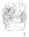
- connection channel arrangement 42 has a first connection channel 47 and a second connection channel 48 connected in parallel therewith. Both connection channels 47, 48 are at one end with the control chamber 22 and the other end with the secondary channel 5 in connection. For this purpose, both connection channels 47, 48 open on both sides separately from each other in the control chamber 22 and the secondary channel 5.
- the separate junction applies only to the control chamber 22.
- the two connection channels 47, 48 are connected together to a single tap channel 52, which opens into the secondary channel 5 with a tap opening 53.
- connection channel assembly 42 includes one of the tap hole 53 outgoing tap channel 52, which splits into the two separately opening into the control chamber 22 first and second connecting channels 47, 48.
- a check valve 54 is turned on, which allows a flow of fluid from the secondary channel 5 in the control chamber when the pressure prevailing in the secondary channel 5 secondary pressure is greater than that prevailing in the control chamber 22, hereinafter referred to as "chamber pressure" , In the opposite direction, the check valve 54 blocks. Thus, if the chamber pressure is higher than the secondary pressure, no fluid passes through the first connection channel 47 therethrough.
- the second connecting channel 48 is expediently designed as a throttle channel and defines a constantly open maximum flow cross-section - hereinafter referred to as "flow cross-section 55" - which is smaller than the flow cross-section released by the second connecting channel 48 at the maximum open check valve 54.
- the difference of these flow cross-sections is relatively large, so that the flow cross-section 55 with respect to the glassgebaren flow cross-section of the check valve 54 may be referred to as a throttle cross-section.
- check valve 54 gives the fluid a large flow cross-section to overflow from the secondary channel 5 in the control chamber 22 free.
- the overflow opening 12 controlling valve member 14 thus switches extremely quickly in the closed position.
- the check valve 54 closes so that the fluid can only flow back from the control chamber 22 into the secondary channel 5 via the reduced flow cross section 55 or throttle cross section of the first connection channel 47. Due to the low fluid flow rate, the control chamber 22 is thereby relieved only slowly, so that the control member 17, the valve member 14 also gradually, quasi “damped” moves to an open position. In this way it is prevented that the control member 17 and the valve member 14 are excited to oscillations of sometimes very large amplitude, which would adversely affect the control behavior and could even damage the components.
- the two connecting channels 47, 48 are formed using bore-like recesses 47a, 48a, which are introduced into the wall of the housing 2, starting from the arranged on the partition wall 28 bottom surface 56 of the control chamber 22.
- a holding sleeve 57 is inserted and in particular screwed in, which by far ends before acting as a valve seat 58 ring stage, between it and the valve seat 58 is a movable in the axial direction, preferably spherical trained Absperrglied 62 is arranged.
- the retaining sleeve 57 axially passing through the cavity forms a longitudinal portion of the first connecting channel 47, through which a fluid flow into the control chamber 22 is possible through when lifted off from the valve seat 58 Absperrglied 62.
- the cross section of the other bore-like depression 48a is greater than the maximum flow cross-section 55 defined by the first connection channel 47.
- the latter is defined by a sleeve-shaped throttle body 64 in the exemplary embodiment, which is inserted into the associated bore-like depression 48a from the control chamber 22, comparable to the retaining sleeve 57 and in particular screwed. Its axially continuous cavity forms a longitudinal section of the second connecting channel 48, this longitudinal section defining the flow cross section 55.
- the throttle body 64 thus acts quasi as an orifice.
- connection channels 47, 48 expediently side by side, in particular in the immediate vicinity in the control chamber 22 a.
- the partition 28 has a radially extending into the secondary channel 5 channel extension 65, in which the two connecting channels 47, 48 and the common tap channel 52 extend.
- the channel course is chosen so that the tap opening 53 opens with all-round radial distance from the peripheral wall 66 of the secondary channel 5 in the secondary channel 5, expediently in the cross-section center of the same.
- the tap opening 53 points in the direction of the secondary connection 7. Due to the flow conditions occurring in the region of the tap opening 53, the chamber pressure is regularly slightly lower than the current secondary pressure, which positively influences the controller characteristic because of the problem of the so-called deforming of the spring device 43 is counteracted occurring detuning.
- connection channels 47, 48 could, for example, also open directly and separately from one another at the peripheral wall 66 radially into the secondary channel 5.
- the second connecting channel 48 is dispensed with and the throttled flow possibility envisaged when the check valve 54 is closed is ensured by the fact that one or more depressions are made in the valve seat 58 and / or on the outer circumference of the blocking member 62, which in the closed position the shut-off member 62 ensure the desired reduced flow cross-section.
- the aspired functional parallel connection of the check valve 54 and a throttle cross-section is thus also guaranteed.
Landscapes
- Physics & Mathematics (AREA)
- Fluid Mechanics (AREA)
- General Physics & Mathematics (AREA)
- Engineering & Computer Science (AREA)
- Automation & Control Theory (AREA)
- Control Of Fluid Pressure (AREA)
Applications Claiming Priority (1)
| Application Number | Priority Date | Filing Date | Title |
|---|---|---|---|
| DE102009014812A DE102009014812A1 (de) | 2009-03-25 | 2009-03-25 | Druckregelventil |
Publications (3)
| Publication Number | Publication Date |
|---|---|
| EP2233998A2 true EP2233998A2 (fr) | 2010-09-29 |
| EP2233998A3 EP2233998A3 (fr) | 2011-07-06 |
| EP2233998B1 EP2233998B1 (fr) | 2018-11-21 |
Family
ID=42244552
Family Applications (1)
| Application Number | Title | Priority Date | Filing Date |
|---|---|---|---|
| EP10002259.9A Active EP2233998B1 (fr) | 2009-03-25 | 2010-03-05 | Soupape de réglage de pression |
Country Status (2)
| Country | Link |
|---|---|
| EP (1) | EP2233998B1 (fr) |
| DE (1) | DE102009014812A1 (fr) |
Cited By (3)
| Publication number | Priority date | Publication date | Assignee | Title |
|---|---|---|---|---|
| CN105373150A (zh) * | 2014-08-12 | 2016-03-02 | 阿自倍尔金门株式会社 | 调节器 |
| CN108693896A (zh) * | 2017-04-07 | 2018-10-23 | 费斯托股份有限两合公司 | 压力调节阀 |
| CN108803692A (zh) * | 2017-05-03 | 2018-11-13 | 费斯托股份有限两合公司 | 气动控制装置和配备有该气动控制装置的过程控制装置 |
Families Citing this family (2)
| Publication number | Priority date | Publication date | Assignee | Title |
|---|---|---|---|---|
| DE202016009065U1 (de) | 2015-08-05 | 2021-11-25 | Knocks Fluid-Technik GmbH | Ventil mit einer Überwachungsfunktion |
| DE102023004566A1 (de) | 2022-11-23 | 2024-05-23 | Knocks Fluid-Technik GmbH | Volumenstromschaltventil |
Citations (2)
| Publication number | Priority date | Publication date | Assignee | Title |
|---|---|---|---|---|
| DE3211889A1 (de) | 1982-03-31 | 1983-10-06 | Elster Ag | Gasdruckregler |
| DE10002752C1 (de) | 2000-01-22 | 2001-06-21 | Festo Ag & Co | Druckregelventil mit Sekundärentlüftungsmaßnahmen |
Family Cites Families (2)
| Publication number | Priority date | Publication date | Assignee | Title |
|---|---|---|---|---|
| DE872908C (de) * | 1951-11-06 | 1953-04-09 | Karlsruhe Augsburg Iweka | Drosseleinrichtung zur Daempfung von Schwingungen bei pneumatisch gesteuerten Ventilen, Dampfdruckminderventilen u. dgl. |
| US3545465A (en) * | 1967-11-29 | 1970-12-08 | Vapor Corp | Pressure regulator |
-
2009
- 2009-03-25 DE DE102009014812A patent/DE102009014812A1/de not_active Withdrawn
-
2010
- 2010-03-05 EP EP10002259.9A patent/EP2233998B1/fr active Active
Patent Citations (2)
| Publication number | Priority date | Publication date | Assignee | Title |
|---|---|---|---|---|
| DE3211889A1 (de) | 1982-03-31 | 1983-10-06 | Elster Ag | Gasdruckregler |
| DE10002752C1 (de) | 2000-01-22 | 2001-06-21 | Festo Ag & Co | Druckregelventil mit Sekundärentlüftungsmaßnahmen |
Cited By (4)
| Publication number | Priority date | Publication date | Assignee | Title |
|---|---|---|---|---|
| CN105373150A (zh) * | 2014-08-12 | 2016-03-02 | 阿自倍尔金门株式会社 | 调节器 |
| EP2993546A1 (fr) * | 2014-08-12 | 2016-03-09 | Azbil Kimmon Co., Ltd. | Régulateur de pression |
| CN108693896A (zh) * | 2017-04-07 | 2018-10-23 | 费斯托股份有限两合公司 | 压力调节阀 |
| CN108803692A (zh) * | 2017-05-03 | 2018-11-13 | 费斯托股份有限两合公司 | 气动控制装置和配备有该气动控制装置的过程控制装置 |
Also Published As
| Publication number | Publication date |
|---|---|
| EP2233998B1 (fr) | 2018-11-21 |
| EP2233998A3 (fr) | 2011-07-06 |
| DE102009014812A1 (de) | 2010-10-07 |
Similar Documents
| Publication | Publication Date | Title |
|---|---|---|
| EP1118921B1 (fr) | Vanne de régulation de pression ayant des moyens secondaires de mise à l'atmosphère | |
| EP1987278B1 (fr) | Soupape pre-asservie de limitation de la pression | |
| DE102011101187B4 (de) | Druckminderer | |
| EP1409873B1 (fr) | Bloc de distribution pour un dispositif de regulation, en particulier une machine hydrostatique | |
| WO1997032136A1 (fr) | Soupape de frein a maintien de charge | |
| EP2233998B1 (fr) | Soupape de réglage de pression | |
| EP0305710B1 (fr) | Dispositif de soupape actionné électromagnétiquement | |
| DE10019254C2 (de) | Drucksteuerventil | |
| DE102013213713A1 (de) | Fluidventil | |
| DE4112065C2 (de) | Vorgesteuertes Druckabschaltventil mit einstellbarer Schaltdruckdifferenz | |
| DE10003136B4 (de) | Hydraulikventil für einen hydraulischen Verbraucher eines Fahrzeuges und Kraftfahrzeug mit demselben | |
| DE4019757A1 (de) | Membrangesteuerter gasdruckregler | |
| DE10135117A1 (de) | Ventileinsatz und Ventil für Gasgeräte | |
| EP1146268A2 (fr) | Dispositif de commande d'une soupape | |
| EP1832950A1 (fr) | Régulateur pour commander une pression utilisateur | |
| DE19944366B4 (de) | Ventil | |
| DE3211889C2 (fr) | ||
| EP2050992B1 (fr) | Dispositif d'aération | |
| WO2007104391A1 (fr) | Agencement de soupape hydraulique | |
| EP0829794A1 (fr) | Soupape de siège de réduction de pression | |
| EP0135751B1 (fr) | Dispositif hydraulique | |
| EP0879374B1 (fr) | Distributeur | |
| EP1686268B1 (fr) | Dispositif hydraulique de contrôle | |
| EP1722143B1 (fr) | Soupape à pression différentielle | |
| EP0772109A1 (fr) | Régulateur de pression de gaz à deux étages |
Legal Events
| Date | Code | Title | Description |
|---|---|---|---|
| PUAI | Public reference made under article 153(3) epc to a published international application that has entered the european phase |
Free format text: ORIGINAL CODE: 0009012 |
|
| AK | Designated contracting states |
Kind code of ref document: A2 Designated state(s): AT BE BG CH CY CZ DE DK EE ES FI FR GB GR HR HU IE IS IT LI LT LU LV MC MK MT NL NO PL PT RO SE SI SK SM TR |
|
| AX | Request for extension of the european patent |
Extension state: AL BA ME RS |
|
| PUAL | Search report despatched |
Free format text: ORIGINAL CODE: 0009013 |
|
| AK | Designated contracting states |
Kind code of ref document: A3 Designated state(s): AT BE BG CH CY CZ DE DK EE ES FI FR GB GR HR HU IE IS IT LI LT LU LV MC MK MT NL NO PL PT RO SE SI SK SM TR |
|
| AX | Request for extension of the european patent |
Extension state: AL BA ME RS |
|
| RIC1 | Information provided on ipc code assigned before grant |
Ipc: G05D 16/02 20060101ALI20110527BHEP Ipc: G05D 16/06 20060101AFI20100622BHEP |
|
| 17P | Request for examination filed |
Effective date: 20111013 |
|
| GRAP | Despatch of communication of intention to grant a patent |
Free format text: ORIGINAL CODE: EPIDOSNIGR1 |
|
| STAA | Information on the status of an ep patent application or granted ep patent |
Free format text: STATUS: GRANT OF PATENT IS INTENDED |
|
| INTG | Intention to grant announced |
Effective date: 20180704 |
|
| GRAS | Grant fee paid |
Free format text: ORIGINAL CODE: EPIDOSNIGR3 |
|
| GRAA | (expected) grant |
Free format text: ORIGINAL CODE: 0009210 |
|
| STAA | Information on the status of an ep patent application or granted ep patent |
Free format text: STATUS: THE PATENT HAS BEEN GRANTED |
|
| AK | Designated contracting states |
Kind code of ref document: B1 Designated state(s): AT BE BG CH CY CZ DE DK EE ES FI FR GB GR HR HU IE IS IT LI LT LU LV MC MK MT NL NO PL PT RO SE SI SK SM TR |
|
| REG | Reference to a national code |
Ref country code: CH Ref legal event code: EP |
|
| REG | Reference to a national code |
Ref country code: IE Ref legal event code: FG4D Free format text: LANGUAGE OF EP DOCUMENT: GERMAN |
|
| REG | Reference to a national code |
Ref country code: DE Ref legal event code: R096 Ref document number: 502010015569 Country of ref document: DE |
|
| REG | Reference to a national code |
Ref country code: AT Ref legal event code: REF Ref document number: 1068289 Country of ref document: AT Kind code of ref document: T Effective date: 20181215 |
|
| REG | Reference to a national code |
Ref country code: NL Ref legal event code: MP Effective date: 20181121 |
|
| PG25 | Lapsed in a contracting state [announced via postgrant information from national office to epo] |
Ref country code: IS Free format text: LAPSE BECAUSE OF FAILURE TO SUBMIT A TRANSLATION OF THE DESCRIPTION OR TO PAY THE FEE WITHIN THE PRESCRIBED TIME-LIMIT Effective date: 20190321 Ref country code: FI Free format text: LAPSE BECAUSE OF FAILURE TO SUBMIT A TRANSLATION OF THE DESCRIPTION OR TO PAY THE FEE WITHIN THE PRESCRIBED TIME-LIMIT Effective date: 20181121 Ref country code: NO Free format text: LAPSE BECAUSE OF FAILURE TO SUBMIT A TRANSLATION OF THE DESCRIPTION OR TO PAY THE FEE WITHIN THE PRESCRIBED TIME-LIMIT Effective date: 20190221 Ref country code: LV Free format text: LAPSE BECAUSE OF FAILURE TO SUBMIT A TRANSLATION OF THE DESCRIPTION OR TO PAY THE FEE WITHIN THE PRESCRIBED TIME-LIMIT Effective date: 20181121 Ref country code: ES Free format text: LAPSE BECAUSE OF FAILURE TO SUBMIT A TRANSLATION OF THE DESCRIPTION OR TO PAY THE FEE WITHIN THE PRESCRIBED TIME-LIMIT Effective date: 20181121 Ref country code: BG Free format text: LAPSE BECAUSE OF FAILURE TO SUBMIT A TRANSLATION OF THE DESCRIPTION OR TO PAY THE FEE WITHIN THE PRESCRIBED TIME-LIMIT Effective date: 20190221 Ref country code: LT Free format text: LAPSE BECAUSE OF FAILURE TO SUBMIT A TRANSLATION OF THE DESCRIPTION OR TO PAY THE FEE WITHIN THE PRESCRIBED TIME-LIMIT Effective date: 20181121 Ref country code: HR Free format text: LAPSE BECAUSE OF FAILURE TO SUBMIT A TRANSLATION OF THE DESCRIPTION OR TO PAY THE FEE WITHIN THE PRESCRIBED TIME-LIMIT Effective date: 20181121 |
|
| PG25 | Lapsed in a contracting state [announced via postgrant information from national office to epo] |
Ref country code: PT Free format text: LAPSE BECAUSE OF FAILURE TO SUBMIT A TRANSLATION OF THE DESCRIPTION OR TO PAY THE FEE WITHIN THE PRESCRIBED TIME-LIMIT Effective date: 20190321 Ref country code: SE Free format text: LAPSE BECAUSE OF FAILURE TO SUBMIT A TRANSLATION OF THE DESCRIPTION OR TO PAY THE FEE WITHIN THE PRESCRIBED TIME-LIMIT Effective date: 20181121 Ref country code: GR Free format text: LAPSE BECAUSE OF FAILURE TO SUBMIT A TRANSLATION OF THE DESCRIPTION OR TO PAY THE FEE WITHIN THE PRESCRIBED TIME-LIMIT Effective date: 20190222 Ref country code: NL Free format text: LAPSE BECAUSE OF FAILURE TO SUBMIT A TRANSLATION OF THE DESCRIPTION OR TO PAY THE FEE WITHIN THE PRESCRIBED TIME-LIMIT Effective date: 20181121 |
|
| PG25 | Lapsed in a contracting state [announced via postgrant information from national office to epo] |
Ref country code: CZ Free format text: LAPSE BECAUSE OF FAILURE TO SUBMIT A TRANSLATION OF THE DESCRIPTION OR TO PAY THE FEE WITHIN THE PRESCRIBED TIME-LIMIT Effective date: 20181121 Ref country code: PL Free format text: LAPSE BECAUSE OF FAILURE TO SUBMIT A TRANSLATION OF THE DESCRIPTION OR TO PAY THE FEE WITHIN THE PRESCRIBED TIME-LIMIT Effective date: 20181121 Ref country code: DK Free format text: LAPSE BECAUSE OF FAILURE TO SUBMIT A TRANSLATION OF THE DESCRIPTION OR TO PAY THE FEE WITHIN THE PRESCRIBED TIME-LIMIT Effective date: 20181121 |
|
| REG | Reference to a national code |
Ref country code: DE Ref legal event code: R097 Ref document number: 502010015569 Country of ref document: DE |
|
| PG25 | Lapsed in a contracting state [announced via postgrant information from national office to epo] |
Ref country code: SM Free format text: LAPSE BECAUSE OF FAILURE TO SUBMIT A TRANSLATION OF THE DESCRIPTION OR TO PAY THE FEE WITHIN THE PRESCRIBED TIME-LIMIT Effective date: 20181121 Ref country code: EE Free format text: LAPSE BECAUSE OF FAILURE TO SUBMIT A TRANSLATION OF THE DESCRIPTION OR TO PAY THE FEE WITHIN THE PRESCRIBED TIME-LIMIT Effective date: 20181121 Ref country code: RO Free format text: LAPSE BECAUSE OF FAILURE TO SUBMIT A TRANSLATION OF THE DESCRIPTION OR TO PAY THE FEE WITHIN THE PRESCRIBED TIME-LIMIT Effective date: 20181121 Ref country code: SK Free format text: LAPSE BECAUSE OF FAILURE TO SUBMIT A TRANSLATION OF THE DESCRIPTION OR TO PAY THE FEE WITHIN THE PRESCRIBED TIME-LIMIT Effective date: 20181121 |
|
| PLBE | No opposition filed within time limit |
Free format text: ORIGINAL CODE: 0009261 |
|
| STAA | Information on the status of an ep patent application or granted ep patent |
Free format text: STATUS: NO OPPOSITION FILED WITHIN TIME LIMIT |
|
| 26N | No opposition filed |
Effective date: 20190822 |
|
| PG25 | Lapsed in a contracting state [announced via postgrant information from national office to epo] |
Ref country code: MC Free format text: LAPSE BECAUSE OF FAILURE TO SUBMIT A TRANSLATION OF THE DESCRIPTION OR TO PAY THE FEE WITHIN THE PRESCRIBED TIME-LIMIT Effective date: 20181121 Ref country code: SI Free format text: LAPSE BECAUSE OF FAILURE TO SUBMIT A TRANSLATION OF THE DESCRIPTION OR TO PAY THE FEE WITHIN THE PRESCRIBED TIME-LIMIT Effective date: 20181121 |
|
| REG | Reference to a national code |
Ref country code: CH Ref legal event code: PL |
|
| GBPC | Gb: european patent ceased through non-payment of renewal fee |
Effective date: 20190305 |
|
| PG25 | Lapsed in a contracting state [announced via postgrant information from national office to epo] |
Ref country code: LU Free format text: LAPSE BECAUSE OF NON-PAYMENT OF DUE FEES Effective date: 20190305 |
|
| REG | Reference to a national code |
Ref country code: BE Ref legal event code: MM Effective date: 20190331 |
|
| PG25 | Lapsed in a contracting state [announced via postgrant information from national office to epo] |
Ref country code: LI Free format text: LAPSE BECAUSE OF NON-PAYMENT OF DUE FEES Effective date: 20190331 Ref country code: CH Free format text: LAPSE BECAUSE OF NON-PAYMENT OF DUE FEES Effective date: 20190331 Ref country code: IE Free format text: LAPSE BECAUSE OF NON-PAYMENT OF DUE FEES Effective date: 20190305 Ref country code: GB Free format text: LAPSE BECAUSE OF NON-PAYMENT OF DUE FEES Effective date: 20190305 |
|
| REG | Reference to a national code |
Ref country code: DE Ref legal event code: R082 Ref document number: 502010015569 Country of ref document: DE Representative=s name: PATENTANWAELTE MAGENBAUER & KOLLEGEN PARTNERSC, DE Ref country code: DE Ref legal event code: R081 Ref document number: 502010015569 Country of ref document: DE Owner name: FESTO SE & CO. KG, DE Free format text: FORMER OWNER: FESTO AG & CO. KG, 73734 ESSLINGEN, DE Ref country code: DE Ref legal event code: R081 Ref document number: 502010015569 Country of ref document: DE Owner name: FESTO AG & CO. KG, DE Free format text: FORMER OWNER: FESTO AG & CO. KG, 73734 ESSLINGEN, DE |
|
| PG25 | Lapsed in a contracting state [announced via postgrant information from national office to epo] |
Ref country code: BE Free format text: LAPSE BECAUSE OF NON-PAYMENT OF DUE FEES Effective date: 20190331 |
|
| PG25 | Lapsed in a contracting state [announced via postgrant information from national office to epo] |
Ref country code: TR Free format text: LAPSE BECAUSE OF FAILURE TO SUBMIT A TRANSLATION OF THE DESCRIPTION OR TO PAY THE FEE WITHIN THE PRESCRIBED TIME-LIMIT Effective date: 20181121 |
|
| PGFP | Annual fee paid to national office [announced via postgrant information from national office to epo] |
Ref country code: IT Payment date: 20200325 Year of fee payment: 11 |
|
| PG25 | Lapsed in a contracting state [announced via postgrant information from national office to epo] |
Ref country code: MT Free format text: LAPSE BECAUSE OF FAILURE TO SUBMIT A TRANSLATION OF THE DESCRIPTION OR TO PAY THE FEE WITHIN THE PRESCRIBED TIME-LIMIT Effective date: 20181121 |
|
| PGFP | Annual fee paid to national office [announced via postgrant information from national office to epo] |
Ref country code: FR Payment date: 20200324 Year of fee payment: 11 |
|
| REG | Reference to a national code |
Ref country code: AT Ref legal event code: MM01 Ref document number: 1068289 Country of ref document: AT Kind code of ref document: T Effective date: 20190305 |
|
| PG25 | Lapsed in a contracting state [announced via postgrant information from national office to epo] |
Ref country code: AT Free format text: LAPSE BECAUSE OF NON-PAYMENT OF DUE FEES Effective date: 20190305 |
|
| PG25 | Lapsed in a contracting state [announced via postgrant information from national office to epo] |
Ref country code: CY Free format text: LAPSE BECAUSE OF FAILURE TO SUBMIT A TRANSLATION OF THE DESCRIPTION OR TO PAY THE FEE WITHIN THE PRESCRIBED TIME-LIMIT Effective date: 20181121 |
|
| PG25 | Lapsed in a contracting state [announced via postgrant information from national office to epo] |
Ref country code: HU Free format text: LAPSE BECAUSE OF FAILURE TO SUBMIT A TRANSLATION OF THE DESCRIPTION OR TO PAY THE FEE WITHIN THE PRESCRIBED TIME-LIMIT; INVALID AB INITIO Effective date: 20100305 |
|
| PG25 | Lapsed in a contracting state [announced via postgrant information from national office to epo] |
Ref country code: FR Free format text: LAPSE BECAUSE OF NON-PAYMENT OF DUE FEES Effective date: 20210331 |
|
| PG25 | Lapsed in a contracting state [announced via postgrant information from national office to epo] |
Ref country code: IT Free format text: LAPSE BECAUSE OF NON-PAYMENT OF DUE FEES Effective date: 20210305 |
|
| PG25 | Lapsed in a contracting state [announced via postgrant information from national office to epo] |
Ref country code: MK Free format text: LAPSE BECAUSE OF FAILURE TO SUBMIT A TRANSLATION OF THE DESCRIPTION OR TO PAY THE FEE WITHIN THE PRESCRIBED TIME-LIMIT Effective date: 20181121 |
|
| PGFP | Annual fee paid to national office [announced via postgrant information from national office to epo] |
Ref country code: DE Payment date: 20260325 Year of fee payment: 17 |