EP2234399A1 - Appareil et procédé de traitement d'images - Google Patents
Appareil et procédé de traitement d'images Download PDFInfo
- Publication number
- EP2234399A1 EP2234399A1 EP09180898A EP09180898A EP2234399A1 EP 2234399 A1 EP2234399 A1 EP 2234399A1 EP 09180898 A EP09180898 A EP 09180898A EP 09180898 A EP09180898 A EP 09180898A EP 2234399 A1 EP2234399 A1 EP 2234399A1
- Authority
- EP
- European Patent Office
- Prior art keywords
- viewing
- vehicle
- information
- image
- image data
- Prior art date
- Legal status (The legal status is an assumption and is not a legal conclusion. Google has not performed a legal analysis and makes no representation as to the accuracy of the status listed.)
- Granted
Links
Images






Classifications
-
- B—PERFORMING OPERATIONS; TRANSPORTING
- B60—VEHICLES IN GENERAL
- B60R—VEHICLES, VEHICLE FITTINGS, OR VEHICLE PARTS, NOT OTHERWISE PROVIDED FOR
- B60R1/00—Optical viewing arrangements; Real-time viewing arrangements for drivers or passengers using optical image capturing systems, e.g. cameras or video systems specially adapted for use in or on vehicles
- B60R1/02—Rear-view mirror arrangements
- B60R1/06—Rear-view mirror arrangements mounted on vehicle exterior
-
- H—ELECTRICITY
- H04—ELECTRIC COMMUNICATION TECHNIQUE
- H04N—PICTORIAL COMMUNICATION, e.g. TELEVISION
- H04N7/00—Television systems
- H04N7/18—Closed-circuit television [CCTV] systems, i.e. systems in which the video signal is not broadcast
- H04N7/181—Closed-circuit television [CCTV] systems, i.e. systems in which the video signal is not broadcast for receiving images from a plurality of remote sources
-
- B—PERFORMING OPERATIONS; TRANSPORTING
- B60—VEHICLES IN GENERAL
- B60R—VEHICLES, VEHICLE FITTINGS, OR VEHICLE PARTS, NOT OTHERWISE PROVIDED FOR
- B60R1/00—Optical viewing arrangements; Real-time viewing arrangements for drivers or passengers using optical image capturing systems, e.g. cameras or video systems specially adapted for use in or on vehicles
- B60R1/20—Real-time viewing arrangements for drivers or passengers using optical image capturing systems, e.g. cameras or video systems specially adapted for use in or on vehicles
- B60R1/22—Real-time viewing arrangements for drivers or passengers using optical image capturing systems, e.g. cameras or video systems specially adapted for use in or on vehicles for viewing an area outside the vehicle, e.g. the exterior of the vehicle
- B60R1/23—Real-time viewing arrangements for drivers or passengers using optical image capturing systems, e.g. cameras or video systems specially adapted for use in or on vehicles for viewing an area outside the vehicle, e.g. the exterior of the vehicle with a predetermined field of view
- B60R1/27—Real-time viewing arrangements for drivers or passengers using optical image capturing systems, e.g. cameras or video systems specially adapted for use in or on vehicles for viewing an area outside the vehicle, e.g. the exterior of the vehicle with a predetermined field of view providing all-round vision, e.g. using omnidirectional cameras
-
- H—ELECTRICITY
- H04—ELECTRIC COMMUNICATION TECHNIQUE
- H04N—PICTORIAL COMMUNICATION, e.g. TELEVISION
- H04N7/00—Television systems
- H04N7/18—Closed-circuit television [CCTV] systems, i.e. systems in which the video signal is not broadcast
-
- B—PERFORMING OPERATIONS; TRANSPORTING
- B60—VEHICLES IN GENERAL
- B60R—VEHICLES, VEHICLE FITTINGS, OR VEHICLE PARTS, NOT OTHERWISE PROVIDED FOR
- B60R2300/00—Details of viewing arrangements using cameras and displays, specially adapted for use in a vehicle
- B60R2300/10—Details of viewing arrangements using cameras and displays, specially adapted for use in a vehicle characterised by the type of camera system used
- B60R2300/102—Details of viewing arrangements using cameras and displays, specially adapted for use in a vehicle characterised by the type of camera system used using 360 degree surveillance camera system
-
- B—PERFORMING OPERATIONS; TRANSPORTING
- B60—VEHICLES IN GENERAL
- B60R—VEHICLES, VEHICLE FITTINGS, OR VEHICLE PARTS, NOT OTHERWISE PROVIDED FOR
- B60R2300/00—Details of viewing arrangements using cameras and displays, specially adapted for use in a vehicle
- B60R2300/10—Details of viewing arrangements using cameras and displays, specially adapted for use in a vehicle characterised by the type of camera system used
- B60R2300/105—Details of viewing arrangements using cameras and displays, specially adapted for use in a vehicle characterised by the type of camera system used using multiple cameras
-
- B—PERFORMING OPERATIONS; TRANSPORTING
- B60—VEHICLES IN GENERAL
- B60R—VEHICLES, VEHICLE FITTINGS, OR VEHICLE PARTS, NOT OTHERWISE PROVIDED FOR
- B60R2300/00—Details of viewing arrangements using cameras and displays, specially adapted for use in a vehicle
- B60R2300/60—Details of viewing arrangements using cameras and displays, specially adapted for use in a vehicle characterised by monitoring and displaying vehicle exterior scenes from a transformed perspective
- B60R2300/602—Details of viewing arrangements using cameras and displays, specially adapted for use in a vehicle characterised by monitoring and displaying vehicle exterior scenes from a transformed perspective with an adjustable viewpoint
-
- B—PERFORMING OPERATIONS; TRANSPORTING
- B60—VEHICLES IN GENERAL
- B60R—VEHICLES, VEHICLE FITTINGS, OR VEHICLE PARTS, NOT OTHERWISE PROVIDED FOR
- B60R2300/00—Details of viewing arrangements using cameras and displays, specially adapted for use in a vehicle
- B60R2300/60—Details of viewing arrangements using cameras and displays, specially adapted for use in a vehicle characterised by monitoring and displaying vehicle exterior scenes from a transformed perspective
- B60R2300/607—Details of viewing arrangements using cameras and displays, specially adapted for use in a vehicle characterised by monitoring and displaying vehicle exterior scenes from a transformed perspective from a bird's eye viewpoint
-
- B—PERFORMING OPERATIONS; TRANSPORTING
- B60—VEHICLES IN GENERAL
- B60R—VEHICLES, VEHICLE FITTINGS, OR VEHICLE PARTS, NOT OTHERWISE PROVIDED FOR
- B60R2300/00—Details of viewing arrangements using cameras and displays, specially adapted for use in a vehicle
- B60R2300/80—Details of viewing arrangements using cameras and displays, specially adapted for use in a vehicle characterised by the intended use of the viewing arrangement
- B60R2300/8093—Details of viewing arrangements using cameras and displays, specially adapted for use in a vehicle characterised by the intended use of the viewing arrangement for obstacle warning
Definitions
- the present invention relates to an image processing method and image processing apparatus that processes a surrounding monitoring image for monitoring the surroundings of a vehicle using image data captured by multiple cameras that are carried by the vehicle.
- Visibility supporting systems have been widely used.
- a camera is mounted onto a rear part or a blind corner of a vehicle such as an automobile, to display the image of a blind spot around the vehicle that is hardly observed by a driver at a driver's seat.
- a driver can perceive the situation of the rear space of the vehicle without turning back by checking the displayed image.
- an apparatus for combining image data is discussed.
- the combination is effected based on the videos obtained by four cameras located on the front, rear, right and left side of a vehicle body, so that a driver can perceive the full surroundings of the vehicle by a single check of the combined image data.
- the apparatus described in the above patent generates an overhead image like a view from above a vehicle to appropriately support the driving operation of a driver of the vehicle.
- the display of an overhead image viewed from above the vehicle on a display screen facilitates the check of the current position of a vehicle and the trace of the vehicle to a target position during parallel parking, garage parking and angled parking, by a driver.
- a driver of a vehicle can check the surroundings of the vehicle by the eyes just before the driver gets in the vehicle. But since a moving object may rapidly approach the vehicle after the driver got in the vehicle, it is desirable to monitor the surroundings of the vehicle including blind spots from a driver's seat using an image.
- the overhead image obtained by the apparatus such as that described in the above patent displays only the close vicinity of the vehicle.
- the monitoring of a vehicle using such image may cause delay in perceiving the approach of a moving object from a far-off point.
- the overhead image viewed from above a vehicle displays the image of an object that is located rearward of the vehicle upside down. This further precludes the driver's correct perception of the object rearward of the vehicle.
- the present invention is achieved in view of the above problems in the art, and is directed to provide an image processing method and image processing apparatus that generates a surrounding monitoring image for monitoring the surroundings of a vehicle by moving a viewpoint while an image of surroundings of the vehicle is displayed, the image being obtained by combining image data from multiple cameras.
- An image processing apparatus includes an in-vehicle image processing apparatus capable to link to multiple cameras mounted to a vehicle, the image processing apparatus comprising: an image memory that stores miltiple image data captured by each of the cameras; a camera-image acquisition unit that inputs and stores the miltiple image data captured by each of the cameras into the image memory; a projection surface geometry manager that manages projection surface geometry information including a set of three-dimensional coordinates for a projection surface that is virtually formed to surround the vehicle; a viewing movement controller that determines viewing information so that a viewpoint and a viewing direction relative to the projection surface are continuously transited according to given viewing transition regulations; an image converter that projects and combines each of the image data stored in the image memory on the projection surface, and converts the combined image data into two-dimensional image data based on the viewing information determined by the viewing movement controller; a display unit that displays the two-dimensional image data converted by the image converter; and a periodic rendering trigger generator that generates a trigger signal to make the image converter start an image conversion process.
- An image processing method is making a computer program cause a computer to function as an in-vehicle image processing apparatus capable to link to multiple cameras mounted to a vehicle, the method comprising: inputting image data captured by the multiple cameras and storing each of the image data into an image memory of the computer by the computer; virtually forming three-dimensional projection surface geometry information around the vehicle, projecting and combining each of the image data stored in the image memory to the projection surface by the computer, and converting the combined image data into two-dimensional image data based on viewing information that is determined according to a given viewing transition regulation by the computer; and displaying the converted two-dimensional image data by the computer.
- a recording medium storing a program for an image processing method comprising: inputting image data captured by the multiple cameras and storing each of the image data into an image memory of the computer by the computer; virtually forming three-dimensional projection surface geometry information around the vehicle, projecting and combining each of the image data stored in the image memory to the projection surface by the computer, and converting the combined image data into two-dimensional image data based on viewing information that is determined according to a given viewing transition regulation by the computer; and displaying the converted two-dimensional image data by the computer.
- the present invention achieves monitoring of the surroundings of a vehicle in various direction in addition to the vicinity of the vehicle based on the continuous transition of viewpoint and viewing direction, and enables an earlier detection of an object that is approaching to the vehicle.
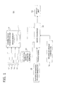
- Fig. 1 is a functional block diagram illustrating an image processing apparatus of a first embodiment.
- a image processing apparatus 100 of the first embodiment includes multiple cameras 101 to 104, an image memory 111, a camera-image acquisition unit 110, a projection surface geometry manager 120, a viewing movement controller 130, an image converter 140, a display unit 150, and a periodic rendering trigger generator 160.
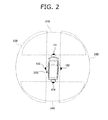
- the multiple cameras 101 to 104 are mounted to the front, rear, right and left part of a vehicle 200 as illustrated in Fig. 2 .
- the number of the camera is not limited to four, but a less number of cameras increases blind spots of the vehicle, and an excessive number of cameras increases image portions overlapping one another.
- the computation required for image processing is also increased in proportion to the number of the cameras.
- Fig. 2 illustrates camera mount positions and image capturing ranges by the cameras.
- the front camera 101 is mounted at the center of the front bumper of the vehicle 200 to capture an image in front of the vehicle 200;
- the rear camera 104 is mounted at the center of the rear bumper of the vehicle 200 to capture an image behind the vehicle 200;
- the right camera 103 is mounted at the center of the right side surface of the vehicle 200 to capture an image on the right side the vehicle 200;
- the left camera 103 is mounted at the center of the left side surface of the vehicle 200 to capture an image on the left side the vehicle 200.
- the cameras 101 to 104 use ultra wide angle lenses, each lens having an angle of view of 180 degrees. This enables, as illustrated in Fig. 2 , the front camera 101 to capture an image of the front area 210; the right camera 102 to capture an image of the right side area 220; the left camera 103 to capture an image of the left side area 230; and the rear camera 104 to capture an image of the back area 240.
- the adjacent areas for the cameras 101 1 to 104 partially overlap each other.
- the cameras 101 to 104 are, as shown, positioned at the centers of the front, right-side, left-side, and rear surfaces of the vehicle 200 respectively, but the positions are not limited to the center, and may be offset from the center as long as the partial overlapping between the adjacent image capturing areas are attained.
- the right camera 102 and the left camera 103 may be mounted to the right and left door mirrors of the vehicle 200, respectively.
- the number of the camera is not limited to four as long as the partial overlapping between the adjacent image capturing areas are attained and the resulting areas surround 360 degrees of the vehicle 200.
- the cameras 101 to 104 each capture images (image data) at 30 frames per second using image pickup devices such as CCDs (Charge Coupled Device) and CMOSs (Complementary Metal Oxide Semiconductor).
- image pickup devices such as CCDs (Charge Coupled Device) and CMOSs (Complementary Metal Oxide Semiconductor).
- the digital image data captured by the cameras 101 to 104 are transmitted to the camera-image acquisition unit 110, and stored in the image memory 111.
- the image memory 111 is configured with a frame buffer that sequentially stores the image data captured by the cameras 101 to 104.
- the camera-image acquisition unit 110 periodically acquires the image data captured by the cameras 101 to 104 for storage of the data in the image memory 111.
- the projection surface geometry manager 120 stores a set of the coordinates of a three-dimensional projection surface that is virtually formed around the vehicle as projection surface geometry information, and may be a record medium such as hard disk or flash memory.
- the viewing movement controller 130 determines viewing information according to given viewing transition regulation so that a viewpoint and a viewing direction are continuously transited relative to the projection surface.
- the image converter 140 projects and combines image data in the image memory 111 on the projection surface, and converts the combined image data into two-dimensional image data based on the viewing information determined by the viewing movement controller 130.
- the display unit 150 displays the image data generated by the image converter 14, and may be a liquid crystal display.
- the display unit 150 may use the display device equipped to a car navigation system.
- the periodic rendering trigger generator 160 generates a trigger signal to start an image conversion process by the image converter 140.
- Fig. 3 is a functional block diagram illustrating a hardware configuration of the image processing apparatus of the first embodiment.
- the image processing apparatus 100 is a computer system including a CPU 301, a ROM 302, a RAM 303, a hard disk drive (HDD) 304, an image buffer 305 (111), an image processer 306, a camera interface 307, a sensor interface 308 and a monitor interface 310.
- a bus 311 Each of the hardware components are connected to one another via a bus 311.
- the CPU 301 controls each of the hardware components, and reads and executes control programs stored in the ROM 302 and the HDD 304 to make the computer having the hardware components operate as an image processing apparatus.
- the ROM 302 stores various control programs and various parameters that are required for the operations of the image processing apparatus 100.
- the RAM 303 is a memory device such as SPAM and flash memory, and temporarily stores various data during the control programs executed by the CPU 301.
- the HDD 304 stores, in advance, the control programs required for the operations of the image processing apparatus 100 and data for three-dimensional image conversion.
- the image buffer 305 stores image data captured by the cameras 101 to 104, and is a memory device such as SPAM and flash memory.
- the image processer 306 performs given image processing on the image data captured by the cameras 101 to 104 and stored in the image buffer 305, and outputs the resulting image data to the display unit 150. After the given image processing, the image processor 306 converts the image data into display data such as data in NTSC (National Television System Committee) standard format, and outputs the display data to the display unit 150.
- NTSC National Television System Committee
- the camera interface 307 is connected to each of the cameras 101 to 104, and transmits the image data captured by each of the cameras 101 to 104, to the image buffer 305 in series for storage.
- the sensor interface 308 is connected to various sensors 309 equipped to the vehicle 200 to store the detection signals detected by the sensors 309 in a given area of the RAM 303 for storage, or to transmit the signals to the CPU 301.
- the various sensors 309 connected to the sensor interface 308 include a vehicle speed sensor, a shift position sensor, a parking brake sensor, a GPS (Global Positioning System) sensor, a steering angle sensor and an obstacle detection sensor.
- a vehicle speed sensor a shift position sensor
- a parking brake sensor a parking brake sensor
- GPS Global Positioning System
- the vehicle speed sensor detects the running speed of a vehicle, and may use a hall element to detect the rotation of a shaft of the vehicle.
- the shift position sensor detects the operating position of a shift lever, and detects the shift position of a gear in a gearbox casing.
- the parking brake sensor detects an application of a parking brake, and may be configured with a relay that is turned on/off by operations of the parking brake lever.
- the steering angle sensor is provided to a rotation shaft of a steering wheel to detect the rotation angle of the steering wheel.
- the GPS sensor has an antenna for receiving radio waves (GPS signals) from multiple GPS satellites, and detects the current position of the vehicle based on the received GPS signals.
- GPS signals radio waves
- the GPS sensor obtains the detected current position as positional information including the data of the latitude, longitude and altitude of the position.
- the obstacle detection sensors are installed in the front bumper and the rear bumper of the vehicle 200 to detect the distance between the vehicle 200 and an obstacle, and may be optical sensors or ultrasonic sensors.
- the signals detected by the sensors 309 are transmitted to the CPU 301 via the sensor interface 308, and are stored in a given area of the RAM 303 as needed.
- the sensors 309 may further include a sensor for detection of a degree of stepping the acceleration pedal and a sensor for detection of a degree of stepping the brake pedal, for example.
- the monitor interface 310 is connected to the display unit 150, and outputs the image data generated as the result of the given image processing by the image processer 306 to the display unit 150.
- the image converter 140 forms a virtual three-dimensional projection surface around the vehicle 200 based on the projection surface geometry stored in the projection surface geometry manager 120, and projects image data from the cameras 101 to 104 to the three-dimensional projection surface.
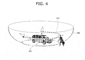
- Fig. 4 illustrates the relationship between a projection surface and viewing transitions.
- a cup-like three-dimensional projection surface 400 is virtually formed around the vehicle 200.
- the projection surface geometry manager 120 stores three-dimensional coordinate information relative to the vehicle 200 as projection surface geometry information for forming the three-dimensional projection surface 400.
- the image converter 140 uses the two-dimensional images captured by the cameras 101 to 104 and stored in the image memory 111, and generates three-dimensional images to be projected to the three-dimensional projection surface 400, based on the projection surface geometry information in the projection surface geometry manager 120.
- the image converter 140 converts the three-dimensional projection surface 400 into two-dimensional image data based on a viewpoint and a viewing direction in viewing information generated by the viewing movement controller 130.
- the viewing movement controller 130 changes the viewpoint and the viewing direction in the viewing information so that a smooth trajectory of viewing transition 410 is drawn, based on given viewing transition regulation.
- Fig. 5 illustrates a viewing transition-regulation memory 500 that stores the viewing transition regulation that is used by the viewing movement controller 130 to transit viewing information.
- the viewing transition-regulation memory 500 is provided in a given memory area, and contains: start-point viewing information 501 of the viewpoint and the viewing direction at the start of viewing transition; end-point viewing information 502 of the viewpoint and the viewing direction at the end of viewing transition; viewing interpolation regulation 503 for interpolation of the transits in the viewing information between the start-point viewing information 501 and the end-point viewing information 502; and current viewing information 504 of the current viewpoint and viewing direction.
- Fig. 6 illustrates viewing information with respect to a vertical cross sectional plane between a viewpoint and a viewing target.
- the viewing information illustrated in Fig. 6 includes: a vertical angle of view 603 that indicates a given angle of the field of view around a view centerline 602 connecting a viewpoint 601 to a viewing target 610 when the vehicle 200 is observed from the viewpoint 601; an elevation angle 604 that is an angle between the horizontal plane where the viewing target 610 resides and the viewpoint 601; and a viewing distance 605 between the viewpoint 601 and the viewing target 610.
- Fig. 7 illustrates viewing information with respect to a horizontal plane.
- the viewing information illustrated in Fig. 7 includes: a vertical angle of view 703 that indicates a given angle of the field of view around a view centerline 702 connecting a viewpoint 601 to a viewing target 610 in a horizontal plane when the vehicle 200 is observed from the viewpoint 601; and a clockwise horizontal angle 704 from the center line that extends forward from the center of the vehicle 200 to the viewpoint 601.
- Fig. 8 illustrates a viewing information table based on the viewing information of Figs. 6 and 7 .
- a viewing information table 800 contains a viewing direction field 810, a viewing target field 820, a viewing distance field 830, and an angle-of-view field 840.
- the viewing direction field 810 stores the information of viewing direction such as the elevation angle 604 illustrated in Fig. 6 and the horizontal angle 704 illustrated in Fig. 7 .
- the viewing target field 820 stores the information of the viewing target 610 at the center of the observation from the viewpoint 601, and the information can be expressed as the coordinate of the viewing target 610 relative to the projection surface stored in the projection surface geometry manager 120.
- the viewing target 610 is the center point of the vehicle 200.
- the viewing distance field 830 stores the viewing distance 605 between the viewpoint 601 and the viewing target 610 illustrated in Fig. 6 .
- the angle-of-view field 840 stores the vertical angle of view 603 of Fig. 6 and the horizontal angle of view 703 of Fig. 7 .
- the vertical angle of view 603 may be equal to the horizontal angle of view 703, and in the case, a single value may be stored as an angle of view.
- Determination of the coordinate of the viewing target 610, the viewing direction based on the elevation angle 604 and the horizontal angle 704, and the viewing distance 605 leads to the coordinate of the viewpoint 601 relative to the projection surface, which determines the viewing information including a viewpoint and a viewing direction.
- the viewing information is transited by the viewing movement controller 130 based on the viewing information in the viewing information table 800, and thereby the start-point viewing information 501 and the end-point viewing information 502 stored in the viewing transition-regulation memory 500 can be expressed by the viewing information based on the viewing information table 800.
- the start-point viewing information 501 may include: the elevation angle 604 of 40 degrees and the horizontal angle 704 of 180 degrees (the viewing direction field 810); the coordinate of the viewing target 610 that is aligned with the center of the vehicle 200 on the projection surface (the viewing target field 820); the viewing distance 605 of 14 m (the viewing distance field 830); and the vertical angle of view 603 of 40 degrees and the horizontal angle of view 703 of 40 degrees (the angle-of-view field 840), and the end-point viewing information 502 may include the same information of the same values as those of the start-point viewing information 50 except the horizontal angle 704 of 540 degrees (the viewing direction field 810).
- the viewing interpolation regulation stored in the viewing interpolation regulation 503 may be designed so that the difference between the value of the start-point viewing information 501 and the value of the end-point viewing information 502 is divided by 180, and the resulting viewing information is applied serially from the start-point viewing information 501 to the end-point viewing information 502 to alter the information therebetween.
- the periodic rendering trigger generator 160 generates a trigger signal for periodic image conversion processing by the image converter 140, and the signal is generated at intervals that provide smooth transit of the viewing of the image data generated by the image converter 140.
- the periodic rendering trigger generator 160 may generate a trigger signal at intervals of 0.1 second for example.
- the viewing movement controller 130 transits the viewing information based on the start-point viewing information 501, the end-point viewing information 502 and the viewing interpolation regulation 503 stored in the viewing transition-regulation memory 500, as described above, for the smooth movement of the viewpoint and the viewing direction corresponding to the viewpoint on the trajectory of viewing transition 410 illustrated in Fig. 4 for example. This realizes the smooth movement and the overall display of the image data around the vehicle 200.
- the combination of the image of the vehicle 200 with the three-dimensional projection surface 400 defines the relationship between the vehicle 200 and the image data around the vehicle 200.
- Fig. 9 is a block diagram illustrating the image processing apparatus 100 that displays an image combined with the image of the vehicle 200.
- Fig. 9 the same elements as those of the image processing apparatus 100 in Fig. 1 are denoted by the same reference numerals as those in Fig. 1 , which will not be described below.
- the image processing apparatus 100 further includes a vehicle-profile memory 910.
- the vehicle-profile memory 910 stores the three-dimensional profile information of the vehicle 200, and the information may include coordinate data and texture data of vehicle profile.
- the image converter 140 projects the image data in the image memory 111 based on the projection surface geometry information in the projection surface geometry manager 120 to the projection surface, and combines the three-dimensional profile information of the vehicle in the vehicle-profile memory 910 with the projection surface.
- the image converter 140 converts the combined image data into a two-dimensional image based on the viewing information obtained from the viewing movement controller 130, and outputs the converted image to the display unit 150.
- the image converter 140 further includes a transmittance processing unit 920.
- the transmittance processing unit 920 changes the manner to display the vehicle when the three-dimensional image of the vehicle is combined with the projected three-dimensional image on the projection surface, based on the three-dimensional profile information of the vehicle in the vehicle-profile memory 910, and displays the three-dimensional image of the vehicle with a higher transmittance by changing the transmittance of the image, or displays the three-dimensional image of the vehicle as wireframes.
- Fig. 10 is an operation chart of an image conversion process by the image processing apparatus 100.
- the image conversion process performed by the image converter 140 is focused on in the following description.
- the image converter 140 checks the receipt of a periodic trigger signal generated by the periodic rendering trigger generator 160.
- the image converter 140 waits for the receipt of a periodic trigger signal from the periodic rendering trigger generator 160, and after determining the receipt of a trigger signal, the image converter 140 proceeds to operation S1020.
- the image converter 140 obtains the projection surface geometry information from the projection surface geometry manager 120 and the three-dimensional profile information of the vehicle from the vehicle-profile memory 910.
- the image converter 140 obtains the image data captured by the cameras 101 to 104 and stored in the image memory 111, and combines each of the image data with the projection surface based on the projection surface geometry information from the projection surface geometry manager 120.
- the image converter 140 determines the transmittance of the three-dimensional profile information of the vehicle that is combined with the image data on the projection surface.
- the transmittance processing unit 920 in the image converter 140 determines the transmittance of the three-dimensional profile information of the vehicle within a range of from 0.0 (opaque) to 1.0 (transparent), and combines the resulting three-dimensional profile information with the three-dimensional projection image.
- the transmittance may have a default value of 0.5, for example, which can be changed based on the positional relationship between an obstacle and a vehicle or a command from an operator.
- Fig. 18 illustrates image data in which the transmittance in the three-dimensional profile information of the vehicle 200 has a value for a translucent image (the transmittance is 0.5).
- the image data 1800 in Fig. 18 is created by combining the three-dimensional image data having the image data captured by the cameras 101 to 104 projected thereon with the three-dimensional vehicle profile information that is processed to have the transmittance of 0.5, on the projection surface 400 that is formed based on the projection surface geometry information stored in the projection surface geometry manager 120.
- the three-dimensional profile information of the vehicle 200 displayed as an translucent image objects beyond the vehicle 200 can be observed through the translucent vehicle 200, which enables the recognition of an obstacle for example in the image data 1800.
- the three-dimensional profile information of a vehicle can be displayed as wireframes.
- the transmittance processing unit 920 creates three-dimensional mesh data with plural polygons based on the vehicle profile information of the vehicle 200 in the vehicle-profile memory 910, which is combined with the three-dimensional image data projected on the projection surface.
- Fig. 19 illustrates image data in which the three-dimensional profile information of the vehicle 200 is displayed as wireframes.
- the image data 1900 in Fig. 19 is created by combining the three-dimensional image data having the image data captured by the cameras 101 to 104 projected thereon with the three-dimensional vehicle profile information as wireframes on the projection surface 400 that is formed based on the projection surface geometry information stored in the projection surface geometry manager 120.
- the three-dimensional profile information of the vehicle 200 displayed as wireframes objects beyond the vehicle 200 can be observed through the wireframes, which enables the recognition of an obstacle for example in the image data 1900.
- the image converter 140 transmits a request for viewing information to the viewing movement controller 130 to generate a two-dimensionally converted image, and obtains current viewing information from the viewing movement controller 130.
- the viewing movement controller 130 calculates the current viewing information on the trajectory of viewing transition 410 based on the viewing information 501, the end-point viewing information 502 and the viewing interpolation regulation 503 stored in the viewing transition-regulation memory 500, and transmits the calculated current viewing information to the image converter 140, and also stores the calculated information in the current viewing information 504.
- the image converter 140 converts the image data that is the combination of the image data projected on the projection surface and the vehicle profile information into two-dimensional image data based on the obtained viewing information.
- the image converter 140 outputs the converted two-dimensional image data to the display unit 150.
- the image converter 140 determines whether the viewing information reaches the end-point viewing information or not. In obtaining the viewing information from the viewing movement controller 130, if the viewing information is the end-point viewing information itself, the image converter 140 receives the notification of the reach, simultaneously. Upon the receipt of the notification from the viewing movement controller 130, the image converter 140 determines that the viewing information have reached the end-point viewing information, and ends the process. Otherwise, the process goes to operation S1010.
- the image converter 140 may be a three-dimensional graphics library software such as OpenGL that operates on a computer system.
- the viewing movement controller 130 generates current viewing information on the trajectory of viewing transition 410 in response to the request from the image converter 140, and transmits the current viewing information to the image converter 140.
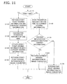
- Fig. 11 is an operation chart of a viewing transition control process by the viewing movement controller 130.
- the viewing movement controller 130 determines whether the request for viewing information from the image converter 140 is the first one or not. If YES in operation S1110, the viewing movement controller 130 proceeds to operation S1120: if No, the viewing movement controller 130 proceeds to operation S1160.
- the viewing movement controller 130 reads the start-point viewing information 501 and the end-point viewing information 502 in the viewing transition-regulation memory 500.
- the viewing movement controller 130 calculates an amount of transition of the viewing information at one time based on the difference between the start-point viewing information 501 and the end-point viewing information 502.
- the start-point viewing information 501 includes: the elevation angle 604 of 40 degrees and the horizontal angle 704 of 180 degrees (the viewing direction field 810); the coordinate of the viewing target 610 that is aligned with the center of the vehicle 200 on the projection surface (the viewing target field 820); the viewing distance 605 of 14 m (the viewing distance field 830); and the vertical angle of view 603 of 40 degrees and the horizontal angle of view 703 of 40 degrees (the angle-of-view field 840), and that the end-point viewing information 502 includes the same information of the same values as those of the start-point viewing information 50 except the horizontal angle 704 of 540 degrees (the viewing direction field 810).
- the only difference between the start-point viewing information 501 and the end-point viewing information 502 is the horizontal angle by 360 degrees.
- the periodic rendering trigger generator 160 when the periodic rendering trigger generator 160 generates a trigger signal at intervals of 0.1 second, ten image data can be generated in one second, and an image entirely surrounding the vehicle 200 can be displayed in 18 seconds. This enables an image display in which the viewing continuously transits in a smooth manner.
- the viewpoint is set to move by two degrees of the horizontal angle at one time, the angle being calculated by dividing 360 by 180.
- the viewing movement controller 130 stores the start-point viewing information 501 into the current viewing information 504.
- the viewing movement controller 130 transmits the start-point viewing information 501 to the image converter 140 as current viewing information 504.
- the viewing movement controller 130 adds the amount of transition for one time to the current viewing information 504.
- the viewing movement controller 130 determines whether the viewing information after the addition exceeds the end-point viewing information 502 or not. If NO in operation S1170, the viewing movement controller 130 proceeds to operation S1180: if YES, the viewing movement controller 130 proceeds to operation S1190.
- the viewing movement controller 130 stores the viewing information after the addition as the current viewing information 504, which is transmitted to the image converter 140.
- the viewing movement controller 130 transmits the end-point viewing information 502 as current viewing information to the image converter 140.
- the viewing movement controller 130 may be configured to store the value of the start-point viewing information 501 as the current viewing information 504 in operation S1190.
- the elevation angle for a viewpoint may be narrowed. This however narrows the field of view within the angle of view. Accordingly, in determining the viewing information, a minimum value of an elevation angle is preferable determined so that the optimal balance of the blind spots and the field of view can be obtained.
- Fig. 12 illustrates determination of a minimum value of an elevation angle for a viewpoint.
- the projection surface 400 is formed around the three-dimensional profile information of the vehicle 200.
- viewpoints 1210 to 1212 with the viewing target being aligned with the center point 1201 of the vehicle 200.
- the elevation angle of the viewpoint 1210 relative to the horizontal plane 1202 that passes through the center point 1201 of the vehicle 200 is larger than that of the viewpoint 1211, and the elevation angle of the viewpoint 1211 is larger than that of the viewpoint 1212.
- the blind spots reside within the area over the horizontal distance 1230 from the point that the extension 1221 of the line from the viewpoint 1210 through the top 1203 of the vehicle 200 crosses the horizontal plane of the projection surface 400 to the center point 1201 of the vehicle 200.
- the blind spots reside within the area over the horizontal distance 1231 from the point that the extension 1223 of the line from the viewpoint 1212 through the top 1203 of the vehicle 200 crosses the horizontal plane of the projection surface 400 to the center point 1201 of the vehicle 200.
- the allowable range for the blind spots of the vehicle 200 is set based on the distance between the point that the extension of the line from the viewpoint through the top 1203 of the vehicle 200 crosses the horizontal plane of the projection surface 400 and the center point of the vehicle 200.
- the elevation angle for the viewpoint is determined based on the range, as the minimum elevation angle.
- the viewing movement controller 130 sets the viewing information to be more than the determined minimum elevation angle, so that the range for blind spots of the vehicle 200 in the image data can be optimized.
- the image converter 140 forms a virtual three-dimensional projection surface 400 around the vehicle 200 corresponding to the projection surface geometry information in the projection surface geometry manager 120, and projects the image data captured by the cameras 101 to 104 onto the projection surface 400.
- the image converter 140 converts the image on the projection surface 400 into two-dimensional image data, if the image includes a field of view outside of the projection surface 400, the converted two-dimensional image data may contain an area without image.
- Fig. 13 illustrates a case where a field of view includes an area outside of a projection surface.
- the projection surface 400 is formed around the three-dimensional profile information of the vehicle 200.
- the viewpoint 1310 has a center line 1311 in the viewing direction for observing the center point of the vehicle 200.
- the angle of view around the view centerline 1311 in the vertical direction is the angle of view 1312, the view centerline 1311 connecting the viewpoint 1310 to the center point of the vehicle 200.
- the upper edge line 1313 of the field of view passes over the projection surface 400 above the upper edge 1331 thereof.
- the selection of the viewing direction at the elevation angle of the viewpoint 1310 in Fig. 13 results in the image data having an area without image data.
- the elevation angle is increased so that the upper edge line 1313 of the field of view passes through the projection surface 400 below the upper edge 1331 thereof.
- Fig. 14 illustrates a case where an elevation angle is increased so that a field of view does not include the upper edge of a projection surface.
- the position of the viewpoint 1310 in Fig. 14 is higher than that of the viewpoint 1310 in Fig. 13 relative to the projection surface 400 in the vertical direction in the coordinate data. This allows the upper edge line 1313 of the field of view to pass below the upper edge 1331 of the projection surface 400, the field of view being determined by the angle of view in the vertical direction.
- the resulting elevation angle 1410 is determined as the minimum elevation angle.
- the viewing movement controller 130 sets the viewing information to be more than the determined minimum elevation angle, so that the images on the projection surface 400 can be converted into two-dimensional image data without an area that does not contain the image data of the projection surface 400.
- an area without image data may appear on the projection surface due to the errors in properties or variation in mount positions of the cameras 101 to 104.
- the area without image data may appear near the upper edge of the projection surface 400.
- Fig. 15 illustrates a case where an area without image data appears on a projection surface as the result of the projection of the image data captured by cameras to the projection surface.
- the projection surface 400 is formed around the three-dimensional profile information of the vehicle 200.
- the viewing movement controller 130 determines a minimum elevation angle so that such area outside of an image range 1510 is not converted into two-dimensional image data, and corrects the viewing information that is selected according to the viewing interpolation regulation 503 in the viewing transition-regulation memory 500, so that the area outside of an image range 1510 is not converted into two-dimensional image data.
- Fig. 16 illustrates image data of the viewing information that is corrected not to include the area outside of an image range.
- the viewing movement controller 130 corrects the viewing information so that the elevation angle exceeds the minimum elevation angle, when the viewing information selected according to the viewing interpolation regulation 503 contains the area outside of an image range 1510 such as that in Fig. 15 . This alters the viewing information to have a larger elevation angle, and generates the image data without the area outside of an image range 1510 as illustrated in Fig. 16 .
- the area outside of an image range 1510 due to the errors in properties or variation in mount positions of the cameras is also eliminated from the field of view, which prevents unnatural lack of an image in converted two-dimensional image data.
- the cameras 101 to 104 are fixedly mounted to the vehicle 200, and each of the cameras 101 to 104 is considered to have property that does not exhibit a significant change in use. Accordingly, a minimum elevation angle at each horizontal angle may be determined by projecting the image data from the cameras 101 to 104 onto the projection surface 400, and rotating the horizontal angles of the viewing information 360 degrees over the upper edges to check the positions of the upper edges of image data.
- Fig. 17 illustrates determination of a minimum elevation angle at each horizontal angle.
- the upper edges 1710 of the projected image data from the cameras 101 to 104 on the projection surface 400 have various heights, and when the viewing information with a constant elevation angle is applied to the image data, the areas outside of an image range may be converted into two-dimensional image data.
- the horizontal angles of the viewing information are rotated 360 degrees over the upper edges to determine a minimum elevation angle for each horizontal angle.
- the viewing movement controller 130 corrects the viewing information to set the elevation angle to be larger than the minimum elevation angle. This eliminates the area outside of an image range from the two-dimensional image data converted by the image converter 140, and prevents unnatural lack of image data.
- Figs. 20 and 21 illustrate setting of start-point viewing information.
- the vehicle 200 is parked with the front side thereof facing the wall of a parking space, and that the front wall and the side walls 2010 are the obstacles for the vehicle 200.
- the vehicle 200 is equipped with an obstacle sensor, and the front and side walls 2010 can be detected as obstacles by the sensor.
- the viewpoint and viewing direction in the start-point viewing information 501 can be set so that the scene a driver approaching the parking space can be reproduced with the viewpoint 2020 at the open side of the parking space and the viewing direction toward the inside of the parking space from the viewpoint 2020.
- the information can be set similarly in the case where the vehicle 200 is parked with one side thereof facing the open side of the parking space.
- the direction for observing the right side of the vehicle 200 from the viewpoint 2120 on the open side of the parking space is set as the start-point viewing information 501.
- the above setting allows the driver who is in the vehicle 200 and checking the surroundings of the vehicle 200 to reproduce the scene the driver approaching the vehicle 200 from outside of the vehicle 200 and checking the surroundings of the vehicle 200 from inside of the vehicle 200.
- the display provides an image of the surroundings of the vehicle 200 that is easy for a driver to perceive, which contributes to the reliable safety check at the start of driving of the vehicle 200.
- Fig. 22 illustrates transition of viewing information when obstacles are detected around a vehicle.
- the vehicle 200 is equipped with obstacle sensors on both sides of a front bumper and both sides of a rear bumper for example, to detect obstacles in all directions in the surroundings of the vehicle 200.
- the viewing information transited by the viewing movement controller 130 is the viewing direction for observing the center point of the vehicle 200 from above the viewpoint 2200.
- the viewing movement controller 130 is configured to reduce the amount of transition of the viewing information when an obstacle is determined to be present within the field of view from a current viewpoint.
- the obstacle sensors of the vehicle 200 detect a first obstacle 2210 on the right side of the vehicle 200, a second obstacle 2220 on the left rear side of the vehicle 200, and a third obstacle 2230 on the left front side of the vehicle 200.
- the obstacle sensors have properties to detect the direction and distance of an obstacle relative to the center point of the vehicle 200.
- the viewing movement controller 130 When determining that the obstacles 2210, 2220 and 2230 are present within the angle of view according to the viewing information set by the viewing movement controller 130, the viewing movement controller 130 reduces the value of interpolation in the viewing interpolation regulation 503 stored in the viewing transition-regulation memory 500. For example, in the case where the viewing movement controller 130 transmits the viewing information including horizontal angle with two-degree increments to the image converter on every request for the viewing information from the image converter 140, when the obstacles 2210, 2220 and 2230 lie within the angle of view, the viewing movement controller 130 may transmit the viewing information including horizontal angle with one-degree increments.
- Fig. 23 illustrates a change in transmittance of the vehicle 200 to increase the visibility of the obstacles around the vehicle 200.
- the vehicle 200 is equipped with obstacle sensors that can detect obstacles around the vehicle 200, and the direction and distance of the obstacle from the vehicle 200.
- the image converter 140 Based on the viewing information from the viewing movement controller 130, when determining that the vehicle 200 lies between an obstacle and the viewpoint, the image converter 140 causes the transmittance processing unit 920 to increase the transmittance for the display of three-dimensional profile information of the vehicle 200.
- the profile information of the vehicle 200 is displayed with a higher transmittance to be combined with the projected image data.
- Fig. 24 is a functional block diagram illustrating an image processing apparatus of a second embodiment.
- Fig. 24 the same elements as those of the image processing apparatus 100 of the first embodiment are denoted by the same reference numerals as those of the first embodiment, which will not be described below.
- the image processing apparatus 100 of the second embodiment is installed in the vehicle 200, and further includes obstacle sensor 2410 for detecting the direction and distance of an obstacle around the vehicle 200 from the vehicle 200, and a vehicle transmittance controller 2420 provided in the viewing movement controller 130.
- the obstacle sensor 2410 is able to detect multiple obstacles in the surroundings of the vehicle 200, and may be sensor devices such as optical sensors and ultrasonic sensors that are assembled in the right and left sides of the front bumper and the rear bumper of the vehicle 200, for example.
- Fig. 25 illustrates obstacle information obtained by the obstacle sensors.
- the obstacle sensor 2410 detects the horizontal angle 2521 where the obstacle 2520 lies and the distance from the center point 2510 of the vehicle 200 to the obstacle 2520, by setting the center line 2521 at zero degrees, the center line 2521 extending from the center point 2510 of the vehicle 200 to the front side of the vehicle 200.
- the obstacle sensor 2410 detects an obstacle as a point that does not contain the information of the height thereof (elevation angle), which means the obstacle sensor 2410 only detects the horizontal angle and distance in an horizontal plane of the obstacle.
- the obstacle information detected by the obstacle sensor 2410 is stored in a given memory area as an obstacle table.
- Fig. 26 illustrates an example of the obstacle table.
- the obstacle table 2600 contains the direction of an obstacle (horizontal angle) 2610 and the distance from the vehicle 200 to the obstacle 2620, and is stored in a given memory area as a record of the obstacle.
- Fig. 27 illustrates the vehicle 200 as viewed from above.
- the vehicle 200 has a width W parallel to the X-axis and a length L parallel to the Y-axis when the lateral line from the center point 2510 of the vehicle 200 serves as the X-axis and the longitudinal line from the center point 2510 serves as the Y-axis.
- the width W and the length L are stored in the vehicle-profile memory 910 as a part of the vehicle profile information.
- the viewing movement controller 130 determines viewing information based on the viewing transition-regulation memory 500 when received a request for the viewing information from the image converter 14, and also calculates the transmittance of the vehicle profile information based on the viewing information, the vehicle profile information in the vehicle-profile memory 910, and the obstacle information detected by the obstacle sensor 2410, and transmits the resulting viewing information and the transmittance to the image converter 140.
- the image converter 140 combines the projection surface geometry in the projection surface geometry manager 120, the image data in the image memory 111, and the three-dimensional profile information of the vehicle 200 in the vehicle-profile memory 910, and the vehicle transmittance received from the viewing movement controller 130 to create three-dimensional image data, and converts the three-dimensional image data into two-dimensional image data based on the viewing information received from the viewing movement controller 130.
- the vehicle transmittance controller 2420 calculates a shielded area behind the vehicle 200 as viewed from the current viewpoint, based on the current viewing information and the vehicle profile information. The calculation of shielded area by the vehicle transmittance controller 2420 is described below with reference to Fig. 28 .
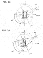
- Fig. 28 illustrates a shielded area when a vehicle is observed from a given viewpoint.
- the viewpoint 2810 in a horizontal plane according to the current viewing information has a coordinate (ex, ey) in the X-Y coordinate system defined with the origin at the center point 2510 of the vehicle 200 which is the viewing target 820. From the viewpoint 2810, a viewing distance 830 extends to the center point 2510 of the vehicle 200 as a distance EL.
- the viewpoint 2810 has a horizontal angle ⁇ from the Y-axis that extends from the center point 2510 of the vehicle 200 to the front side of the vehicle 200 (upward in Fig. 28 ).
- the vehicle 200 have four corners: a right front corner C1 (W/2, L/2); a right rear corner C2 (W/2, -L/2); a left rear corner C3 (-W/2, -L/2); and a left front corner C4 (-W/2, L/2).
- the area between the extensions from the viewpoint 2810 through each of the corners C1 to C4 is the shielded angle range 2820.
- the shielded angle range 2820 is defined between the straight line LN2 extending from the viewpoint 2810 through the right rear corner C2 and the straight line LN4 extending from the viewpoint 2810 through the left front corner C4.
- the shielded area shielded by the vehicle profile information of the vehicle lies on the side of the straight line LN24 opposite to the viewpoint 2810, the straight line LN24 passing the right rear corner C2 and the left front corner C4.
- LN2 and LN4 that defme the shielded angle range 2820 can be expressed in the following equations.
- the vehicle transmittance controller 2420 determines whether the obstacle information obtained from the obstacle sensor 2410 is present within the shielded area or not in the coordinate space having the viewpoint 2810 therein. The determination of the presence is described below with reference to Fig. 29 .
- Fig. 29 illustrates the relationship between obstacle information and a shielded area.
- the vehicle transmittance controller 2420 determines the obstacle position H in the X-Y coordinate system based on the obstacle information from the obstacle sensor 2410.
- the vehicle transmittance controller 2420 determines whether the obstacle position H is present within the shielded area or not based on the determined obstacle position H.
- Each of the straight line LN2 from viewpoint 2810 through the right rear corner C2 of the vehicle 200, the straight line LN4 from viewpoint 2810 through the left front corner C4 of the vehicle 200, and the straight line LN24 passing through right rear corner C2 and the left front corner C4 of the vehicle 200 has a vector in a given direction.
- the straight line LN2 has a first vector (E, C2) pointing from the viewpoint 2810 toward the right rear corner C2
- the straight line LN4 has a second vector (C4, E) pointing from the left front corner C4 toward the viewpoint 2810
- the straight line LN24 has a third vector (C4, C2) pointing from the left front corner C4 toward the right rear corner C2.
- the obstacle position H resides on the right side of the vectors when seen in the pointing direction along each of the vectors, the obstacle position H is determined to be present within the shielded area of the vehicle 200 as seen from the viewpoint 2810.
- the obstacle position H after the transformation has a negative coordinate, the obstacle position H is determined to be present on the right side of the vector.
- the vehicle transmittance controller 2420 performs the above process on each of the first to third vectors.
- the vehicle transmittance controller 2420 determines that the obstacle position H is present on the right side of each of the vectors, the obstacle position H is determined to be present within the shielded area of the vehicle 200.
- the vehicle transmittance controller 2420 transmits the request for obstacle information to each of the obstacle sensors 2410, and creates a obstacle table of obstacle information 2600 such as that illustrated in Fig. 26 .
- the vehicle transmittance controller 2420 determines whether each obstacle information in the obstacle table 2600 is present within the shielded area of the vehicle 200 or not. When determining the presence of at least one obstacle within the shielded area of the vehicle 200, the vehicle transmittance controller 2420 increases the transmittance of the vehicle 200 from the normal value: whereas when determining no presence, the vehicle transmittance controller 2420 transmits the normal vehicle transmittance to the image converter 140.
- the normal vehicle transmittance has a value of 0.5, and can be changed into 0.8 for the presence of an obstacle within the shielded area of the vehicle 200.
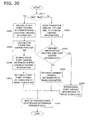
- Fig. 30 is an operation chart of a viewing transition process including the calculation of vehicle transmittance by the viewing movement controller. The process in the flowchart in Fig. 30 , although similar to that for viewing transition in Fig. 11 , is described below in order.
- the viewing movement controller 130 determines whether the request for viewing information from the image converter 140 is the first one or not. If YES in operation S3010, the viewing movement controller 130 proceeds to operation S3020: if No, the viewing movement controller 130 proceeds to operation S3060.
- the viewing movement controller 130 reads the start-point viewing information 501 and the end-point viewing information 502 from the viewing transition-regulation memory 500.
- the viewing movement controller 130 calculates an amount of transition of the viewing information at one time based on the difference between the start-point viewing information 501 and the end-point viewing information 502. The calculation is performed as described above.
- the viewing movement controller 130 stores the start-point viewing information 501 into the current viewing information 504.
- the viewing movement controller 130 transmits the start-point viewing information 501 as current viewing information to the image converter 140.
- the viewing movement controller 130 adds the amount of transition for one time to the current viewing information 504.
- the viewing movement controller 130 determines whether the viewing information after the addition exceeds the end-point viewing information 502 or not. If NO in operation S3070, the viewing movement controller 130 proceeds to operation S3080: if YES, the viewing movement controller 130 proceeds to operation S3090.
- the viewing movement controller 130 stores the viewing information after the addition as the current viewing information 504, which is transmitted to the image converter 140.
- the viewing movement controller 130 transmits the end-point viewing information 502 as current viewing information to the image converter 140.
- the vehicle transmittance controller 2420 determines whether an obstacle is present within the shielded area of the vehicle 200 or not, and determines a vehicle transmittance, which is sent to the image converter 140.
- Fig. 31 is an operation chart of a vehicle transmittance determination process by the vehicle transmittance controller 2420.
- the viewing movement controller 130 determines viewing information according to the viewing transition-regulation memory 500 when received a request for the viewing information from the image converter 14.
- the vehicle transmittance controller 2420 determines a vehicle transmittance based on the determined viewing information.
- the vehicle transmittance controller 2420 after the receipt of the current viewing information, reads the width W and the length L of the vehicle 200 stored in the vehicle-profile memory 910.
- the vehicle transmittance controller 2420 calculates the shielded area shielded by the vehicle 200. The calculation is performed using the equation for the lines between a viewpoint and the corners of the vehicle 200, which defines the shielded angle range 2820.
- the vehicle transmittance controller 2420 obtains obstacle information of one or multiple obstacles from the obstacle table 2600 that is created based on the obstacle information from the obstacle sensor 2410.
- the vehicle transmittance controller 2420 examines the obtained obstacle information by determining if the position of the obstacle is present within the shielded area of the vehicle 200.
- the presence of the obstacle within the shielded area of the vehicle 200 can be determined based on the relationship between the vectors on the lines between the viewpoint and the corners of the vehicle 200 and the position of the obstacle.
- the presence can be determined based on the position of the obstacle in the X-Y coordinate system. The presence, however, may be determined by any other methods.
- each of the obstacles is determined whether present within the shielded area of the vehicle 200 or not.
- the vehicle transmittance controller 2420 determines whether there is at least one obstacle within the shielded area of the vehicle 200. If YES in operation S3150, the vehicle transmittance controller 2420 proceeds to operation S3160; if NO in operation S3150, the vehicle transmittance controller 2420 proceeds to operation S3170.
- the vehicle transmittance controller 2420 increases the vehicle transmittance from the normal value.
- the transmittance can be increased to 0.8 from the normal value of 0.5.
- the vehicle transmittance controller 2420 uses the vehicle transmittance of the normal value.
- the vehicle transmittance controller 2420 selects the value.
- the vehicle transmittance controller 2420 transmits the selected vehicle transmittance to the image converter 140.
- the image converter 140 changes the transmittance included in the vehicle profile information in the vehicle-profile memory 910 based on the vehicle transmittance from the viewing movement controller 130, and creates a combined image using the projection surface geometry information in the projection surface geometry manager 120 and the image data in the image memory 111, and converts the combined data into two-dimensional image data based on the viewing information from the viewing movement controller 130.
- the transmittance in the vehicle profile information that is combined with the image data is increased. This facilitates the recognition of the obstacle, assures the recognition of the obstacle by the driver, and prevents contact of the vehicle with the obstacle.
- a GPS (Global Positioning System) receiver on the vehicle may be used to change start-point viewing information by obtaining the positional and directional information of the vehicle and time data via the radio waves from satellites, and determining the current direction of the sunlight and the current running direction of the vehicle.
- GPS Global Positioning System
- the viewing movement controller 130 determines the direction of the sunlight and the running direction of the vehicle 200 based on the directional information and time data from the GPS receiver.
- the viewing movement controller 130 When determining that the start-point viewing information 501 has a horizontal angle of about 180 degrees relative to the direction of the sunlight, the viewing movement controller 130 changes the start-point viewing information 501 to be parallel to or generally parallel to the direction of the sunlight.
- the image data from the cameras 101 to 104 are combined to be projected on the projection surface. If the viewing direction to the projection surface has a horizontal angle of about 180 degrees relative to the direction of the sunlight, the projected image cannot be clearly seen by a driver due to the direct sunlight. Thus, the directions of the vehicle 200 and the sunlight are determined using the radio waves received at the GPS receiver, so that the transition of the viewing information is started from a viewpoint where a driver can see the image data easily, which facilitates the recognition of the surroundings of the vehicle by the driver.
- the information of a driver's seat indicating that the driver's seat is on the right or left side of a vehicle may be stored in a given memory area, so that the transition of viewing information may be started from the image data on the opposite side of a driver's seat of the vehicle.
- the blind spot is likely to be on the opposite side of the driver's seat.
- the opposite side of the driver's seat is stored as the area where a blind spot often exists in the start-point viewing information 501. This facilitates the recognition of an obstacle.
- the viewing information may be set to display the overall surroundings from the driver's seat.
- the viewpoint at the driver's seat is set as the start-point viewing information 501, so that the viewing information can be transited from the front side, the right side, the back side, the left side, and the front side again with respect to the driver's seat.
- the end-point viewing information may be set at the position outside of the vehicle.
- the viewing interpolation regulation 503 can be set so that the viewing information can be continuously transited in a smooth manner from start-point viewing information 501 that is the driver's viewpoint at the driver's seat to the end-point viewing information 502 at a given position outside of the vehicle 200.
- the continuous and smooth transition of the viewing information allows the driver to check the surroundings of the vehicle 200 without discomfort.
- the end-point viewing information 502 may be a viewpoint right above the vehicle 200 for looking down the vehicle 200 below.
- This setting supports the driver's operation at the parking of the vehicle into a parking space and the starting of the vehicle from the parking space.
- the above described image processing for combining and displaying image data around the vehicle 200 with the viewing information being transited can be actuated by the operation of a switch provided to the processor by a driver.
- the periodic rendering trigger generator 160 may generates a trigger signal after receiving an actuation signal of the car navigation system from an actuation signal receiver that is provided to receive the actuation signal of the car navigation system.
- the periodic rendering trigger generator 160 may generate a trigger signal after receiving a starting signal of the engine of the vehicle from a starting signal receiver that is provided to receive the starting signal indicating the starting of the engine.
- the present invention is applicable to an in-vehicle image processing apparatus that provides a monitor screen that can be seen from a driver's seat, and can be used as a vehicle surrounding monitoring system for monitoring the surroundings of the vehicle, and facilitates for a driver to perceive the situation of the vehicle and the surrounding of the vehicle from an observation viewpoint inside or outside of the vehicle.
Landscapes
- Engineering & Computer Science (AREA)
- Multimedia (AREA)
- Mechanical Engineering (AREA)
- Signal Processing (AREA)
- Closed-Circuit Television Systems (AREA)
- Image Processing (AREA)
- Image Analysis (AREA)
- Fittings On The Vehicle Exterior For Carrying Loads, And Devices For Holding Or Mounting Articles (AREA)
- Processing Or Creating Images (AREA)
Applications Claiming Priority (1)
| Application Number | Priority Date | Filing Date | Title |
|---|---|---|---|
| JP2009075166A JP5439890B2 (ja) | 2009-03-25 | 2009-03-25 | 画像処理方法、画像処理装置及びプログラム |
Publications (2)
| Publication Number | Publication Date |
|---|---|
| EP2234399A1 true EP2234399A1 (fr) | 2010-09-29 |
| EP2234399B1 EP2234399B1 (fr) | 2016-08-17 |
Family
ID=42232613
Family Applications (1)
| Application Number | Title | Priority Date | Filing Date |
|---|---|---|---|
| EP09180898.0A Revoked EP2234399B1 (fr) | 2009-03-25 | 2009-12-29 | Appareil et procédé de traitement d'images |
Country Status (4)
| Country | Link |
|---|---|
| US (1) | US8576285B2 (fr) |
| EP (1) | EP2234399B1 (fr) |
| JP (1) | JP5439890B2 (fr) |
| KR (1) | KR101295295B1 (fr) |
Cited By (15)
| Publication number | Priority date | Publication date | Assignee | Title |
|---|---|---|---|---|
| CN102729911A (zh) * | 2011-04-14 | 2012-10-17 | 哈曼贝克自动系统股份有限公司 | 车辆环景显示系统 |
| EP2554434A1 (fr) * | 2011-08-05 | 2013-02-06 | Harman Becker Automotive Systems GmbH | Système de visualisation panoramique de véhicule |
| WO2013053590A1 (fr) * | 2011-10-14 | 2013-04-18 | Robert Bosch Gmbh | Procédé de représentation du champ périphérique d'un véhicule |
| EP2724896A4 (fr) * | 2011-06-27 | 2015-05-06 | Clarion Co Ltd | Dispositif d'aide au stationnement |
| US9311706B2 (en) | 2011-06-01 | 2016-04-12 | Harman Becker Automotive Systems Gmbh | System for calibrating a vision system |
| CN102729911B (zh) * | 2011-04-14 | 2016-11-30 | 哈曼贝克自动系统股份有限公司 | 车辆环景显示系统 |
| US9536306B2 (en) | 2011-06-30 | 2017-01-03 | Harman Becker Automotive Systems Gmbh | Vehicle vision system |
| EP2973420A4 (fr) * | 2013-03-14 | 2017-07-26 | Robert Bosch GmbH | Système et procédé pour la correction de distorsion dans la visualisation d'environnement tridimensionnel |
| CN107850902A (zh) * | 2015-07-08 | 2018-03-27 | 深圳市大疆创新科技有限公司 | 可移动物体上的相机配置 |
| WO2019149499A1 (fr) * | 2018-01-30 | 2019-08-08 | Connaught Electronics Ltd. | Procédé de représentation d'une région environnementale d'un véhicule automobile au moyen d'une fenêtre d'image dans une image, produit programme d'ordinateur ainsi que système d'affichage |
| WO2020200373A1 (fr) * | 2019-04-02 | 2020-10-08 | Conti Temic Microelectronic Gmbh | Système d'aide au stationnement |
| WO2021110412A1 (fr) * | 2019-12-05 | 2021-06-10 | Robert Bosch Gmbh | Procédé d'affichage destiné à afficher un modèle d'environnement d'un véhicule, programme informatique, dispositif de commande et véhicule |
| DE102013215483B4 (de) | 2013-08-06 | 2023-05-17 | Bayerische Motoren Werke Aktiengesellschaft | Anzeigesystem, Visualisierungsverfahren für ein Fahrzeug und computerlesbares Speichermedium zur Implementierung des Verfahrens |
| US11661722B2 (en) | 2020-11-19 | 2023-05-30 | Deere & Company | System and method for customized visualization of the surroundings of self-propelled work vehicles |
| DE102020203297B4 (de) | 2020-03-13 | 2024-08-01 | Volkswagen Aktiengesellschaft | Verfahren und Vorrichtung zur Darstellung von Informationen in einer erweiterten Realitätsanwendung |
Families Citing this family (77)
| Publication number | Priority date | Publication date | Assignee | Title |
|---|---|---|---|---|
| JP6005115B2 (ja) * | 2009-05-29 | 2016-10-12 | 富士通テン株式会社 | 画像処理装置、電子装置、および、画像処理方法 |
| JP5627253B2 (ja) | 2009-05-29 | 2014-11-19 | 富士通テン株式会社 | 画像処理装置、電子装置、および、画像処理方法 |
| US20110169957A1 (en) * | 2010-01-14 | 2011-07-14 | Ford Global Technologies, Llc | Vehicle Image Processing Method |
| JP5362639B2 (ja) * | 2010-04-12 | 2013-12-11 | 住友重機械工業株式会社 | 画像生成装置及び操作支援システム |
| JP5549436B2 (ja) * | 2010-07-06 | 2014-07-16 | 日産自動車株式会社 | 車両用監視装置 |
| KR101852811B1 (ko) * | 2011-01-05 | 2018-04-27 | 엘지전자 주식회사 | 영상표시 장치 및 그 제어방법 |
| JP5338838B2 (ja) * | 2011-03-31 | 2013-11-13 | アイシン・エィ・ダブリュ株式会社 | 移動案内表示システム、移動案内表示方法及びコンピュータプログラム |
| US8952799B2 (en) * | 2011-04-12 | 2015-02-10 | Conti Temic Microelectronic Gmbh | Method and system for warning a driver of a vehicle about potential obstacles behind the vehicle |
| JP5058354B1 (ja) * | 2011-04-19 | 2012-10-24 | 株式会社東芝 | 電子機器、表示制御方法及びプログラム |
| GB201116960D0 (en) | 2011-09-30 | 2011-11-16 | Bae Systems Plc | Monocular camera localisation using prior point clouds |
| GB201116961D0 (en) | 2011-09-30 | 2011-11-16 | Bae Systems Plc | Fast calibration for lidars |
| GB201116958D0 (en) * | 2011-09-30 | 2011-11-16 | Bae Systems Plc | Use of synthetic overhead images for vehicle localisation |
| GB201116959D0 (en) | 2011-09-30 | 2011-11-16 | Bae Systems Plc | Vehicle localisation with 2d laser scanner and 3d prior scans |
| KR101316501B1 (ko) * | 2011-10-14 | 2013-10-10 | 현대자동차주식회사 | 메쉬형 공간 해석기법을 이용한 주차 공간 탐지방법 및 그 시스템 |
| DE102011084554A1 (de) * | 2011-10-14 | 2013-04-18 | Robert Bosch Gmbh | Verfahren zur Darstellung eines Fahrzeugumfeldes |
| KR101265711B1 (ko) * | 2011-11-30 | 2013-05-20 | 주식회사 이미지넥스트 | 3d 차량 주변 영상 생성 방법 및 장치 |
| DE102012204541B4 (de) * | 2012-03-21 | 2024-01-25 | Bayerische Motoren Werke Aktiengesellschaft | Verfahren und Vorrichtung zur Bildverarbeitung von Bilddaten |
| JP5911775B2 (ja) * | 2012-08-21 | 2016-04-27 | 富士通テン株式会社 | 画像生成装置、画像表示システム及び画像生成方法 |
| DE102012018325A1 (de) * | 2012-09-15 | 2014-03-20 | DSP-Weuffen GmbH | Verfahren und Vorrichtung für ein bildgebendes Fahrerassistenzsystem mit adaptiver Umsichtdarstellung |
| JP6014433B2 (ja) * | 2012-09-19 | 2016-10-25 | 富士通テン株式会社 | 画像処理装置、画像処理方法、及び、画像処理システム |
| JP6014442B2 (ja) | 2012-09-27 | 2016-10-25 | 富士通テン株式会社 | 画像生成装置、画像表示システム、および、画像生成方法 |
| JP6079131B2 (ja) * | 2012-10-25 | 2017-02-15 | 富士通株式会社 | 画像処理装置、方法、及びプログラム |
| US10168871B2 (en) | 2013-09-16 | 2019-01-01 | Rovi Guides, Inc. | Methods and systems for presenting direction-specific media assets |
| CN105556956B (zh) * | 2013-09-19 | 2019-01-22 | 富士通天株式会社 | 图像生成装置、图像显示系统、图像生成方法以及图像显示方法 |
| JP6258000B2 (ja) * | 2013-10-31 | 2018-01-10 | 株式会社デンソーテン | 画像表示システム、画像表示方法及びプログラム |
| JP6257978B2 (ja) * | 2013-09-19 | 2018-01-10 | 株式会社デンソーテン | 画像生成装置、画像表示システム及び画像生成方法 |
| DE102013220005A1 (de) * | 2013-10-02 | 2015-04-02 | Continental Automotive Gmbh | Verfahren und Vorrichtung zur Anzeige der Umgebung eines Fahrzeugs und Fahrerassistenzsystem |
| TWI528325B (zh) * | 2013-10-18 | 2016-04-01 | 財團法人資訊工業策進會 | 影像處理方法及應用影像處理方法之系統 |
| KR102179154B1 (ko) * | 2013-11-27 | 2020-11-16 | 한국전자통신연구원 | 투명 디스플레이를 이용한 전자기기 제어방법 및 이를 이용한 장치 |
| CN105765966B (zh) | 2013-12-19 | 2020-07-10 | 英特尔公司 | 碗形成像系统 |
| US9272709B2 (en) * | 2014-01-30 | 2016-03-01 | Mobileye Vision Technologies Ltd. | Systems and methods for detecting traffic lights |
| US10442355B2 (en) | 2014-09-17 | 2019-10-15 | Intel Corporation | Object visualization in bowl-shaped imaging systems |
| JP6548900B2 (ja) | 2015-01-20 | 2019-07-24 | 株式会社デンソーテン | 画像生成装置、画像生成方法及びプログラム |
| KR102261312B1 (ko) * | 2015-04-21 | 2021-06-08 | 주식회사 만도 | 다중 카메라 운전 보조 시스템 |
| JP6187534B2 (ja) * | 2015-05-11 | 2017-08-30 | トヨタ自動車株式会社 | 車両の規制速度表示装置 |
| JP6610140B2 (ja) * | 2015-09-30 | 2019-11-27 | アイシン精機株式会社 | 周辺監視装置 |
| JP6575445B2 (ja) * | 2015-09-30 | 2019-09-18 | アイシン精機株式会社 | 車両用画像処理装置 |
| WO2017061515A1 (fr) * | 2015-10-05 | 2017-04-13 | 株式会社小松製作所 | Machine de construction et système de gestion de construction |
| US9950669B2 (en) | 2015-11-12 | 2018-04-24 | Robert Bosch Gmbh | Vehicle camera system with multiple-camera alignment |
| US11184531B2 (en) | 2015-12-21 | 2021-11-23 | Robert Bosch Gmbh | Dynamic image blending for multiple-camera vehicle systems |
| JP2017059196A (ja) * | 2015-12-22 | 2017-03-23 | 株式会社コロプラ | 仮想現実空間映像表示方法、及び、プログラム |
| US10019054B2 (en) * | 2015-12-30 | 2018-07-10 | Thunder Power New Energy Vehicle Development Company Limited | Remote driving with a virtual reality system |
| US9568995B1 (en) * | 2015-12-30 | 2017-02-14 | Thunder Power Hong Kong Ltd. | Remote driving with a virtual reality system |
| JP6662175B2 (ja) * | 2016-04-21 | 2020-03-11 | 日産自動車株式会社 | 表示方法及び運転支援装置 |
| JP6649178B2 (ja) * | 2016-05-24 | 2020-02-19 | 株式会社東芝 | 情報処理装置、および、情報処理方法 |
| DE102016211453A1 (de) * | 2016-06-27 | 2017-12-28 | Conti Temic Microelectronic Gmbh | Verfahren und Fahrzeugsteuersystem zum Erzeugen von Abbildungen eines Umfeldmodells und entsprechendes Fahrzeug |
| JP6766557B2 (ja) * | 2016-09-29 | 2020-10-14 | アイシン精機株式会社 | 周辺監視装置 |
| JP6876236B2 (ja) * | 2016-09-30 | 2021-05-26 | 株式会社アイシン | 表示制御装置 |
| JP2018110328A (ja) | 2017-01-04 | 2018-07-12 | 株式会社デンソーテン | 画像処理装置および画像処理方法 |
| EP3537714B1 (fr) * | 2017-02-28 | 2021-08-25 | JVC Kenwood Corporation | Dispositif, système et procédé de génération d'image vidéo de vue à vol d'oiseau et programme associé |
| JP6760129B2 (ja) * | 2017-02-28 | 2020-09-23 | 株式会社Jvcケンウッド | 俯瞰映像生成装置、俯瞰映像生成システム、俯瞰映像生成方法およびプログラム |
| JP6724821B2 (ja) * | 2017-02-28 | 2020-07-15 | 株式会社Jvcケンウッド | 俯瞰映像生成装置、俯瞰映像生成システム、俯瞰映像生成方法およびプログラム |
| US10861359B2 (en) * | 2017-05-16 | 2020-12-08 | Texas Instruments Incorporated | Surround-view with seamless transition to 3D view system and method |
| JP6962036B2 (ja) * | 2017-07-07 | 2021-11-05 | 株式会社アイシン | 周辺監視装置 |
| WO2019038901A1 (fr) * | 2017-08-25 | 2019-02-28 | 株式会社ソシオネクスト | Dispositif et programme de correction, et support d'enregistrement |
| JP7013751B2 (ja) * | 2017-09-15 | 2022-02-01 | 株式会社アイシン | 画像処理装置 |
| JP6958163B2 (ja) * | 2017-09-20 | 2021-11-02 | 株式会社アイシン | 表示制御装置 |
| JP7140487B2 (ja) * | 2017-10-25 | 2022-09-21 | キヤノン株式会社 | 情報処理装置、表示制御方法、及び、プログラム |
| JP7106846B2 (ja) * | 2017-11-24 | 2022-07-27 | 株式会社アイシン | 周辺監視装置 |
| KR102030631B1 (ko) * | 2018-02-27 | 2019-10-10 | (주)넥셀 | 어라운드뷰 제공 방법 및 장치 |
| JP6607272B2 (ja) * | 2018-03-02 | 2019-11-20 | 株式会社Jvcケンウッド | 車両用記録装置、車両用記録方法及びプログラム |
| US10755112B2 (en) | 2018-03-13 | 2020-08-25 | Toyota Research Institute, Inc. | Systems and methods for reducing data storage in machine learning |
| JP7151293B2 (ja) * | 2018-09-06 | 2022-10-12 | 株式会社アイシン | 車両周辺表示装置 |
| JP7172309B2 (ja) * | 2018-09-06 | 2022-11-16 | 株式会社アイシン | 周辺監視装置 |
| JP7283059B2 (ja) * | 2018-11-28 | 2023-05-30 | 株式会社アイシン | 周辺監視装置 |
| KR102177878B1 (ko) * | 2019-03-11 | 2020-11-12 | 현대모비스 주식회사 | 영상 처리 장치 및 방법 |
| KR102281609B1 (ko) | 2020-01-16 | 2021-07-29 | 현대모비스 주식회사 | 어라운드뷰 합성 시스템 및 방법 |
| JP7622748B2 (ja) * | 2020-10-09 | 2025-01-28 | 株式会社ソシオネクスト | 画像処理装置、画像処理方法、及び画像処理プログラム |
| JP7523196B2 (ja) * | 2020-12-16 | 2024-07-26 | 株式会社デンソー | 周辺画像表示装置 |
| CN112509179B (zh) * | 2020-12-18 | 2024-07-30 | 大连理工大学 | 具有全向碰撞感知和车内外三维场景重现的汽车黑匣子 |
| KR102473407B1 (ko) * | 2020-12-28 | 2022-12-05 | 삼성전기주식회사 | 틸트 카메라를 이용한 차량의 svm 시스템 |
| CN117356087A (zh) * | 2021-05-26 | 2024-01-05 | 株式会社索思未来 | 图像处理装置、图像处理方法及图像处理程序 |
| GB2621979A (en) * | 2022-08-23 | 2024-03-06 | Continental Automotive Gmbh | Method and device for generating an outsider perspective image and method of training a neural network |
| JP2024106677A (ja) * | 2023-01-27 | 2024-08-08 | 本田技研工業株式会社 | 画像処理装置 |
| KR102695932B1 (ko) * | 2023-04-15 | 2024-08-16 | 주식회사 리트빅 | 주행상황 재현 기반의 svm 녹화 재생 장치 |
| US12505612B2 (en) * | 2023-09-07 | 2025-12-23 | Valeo Comfort And Driving Assistance | Systems and methods for dynamic three-dimensional model lighting and realistic shadow rendering in automotive mixed reality applications |
| WO2025197107A1 (fr) * | 2024-03-22 | 2025-09-25 | 日産自動車株式会社 | Dispositif de commande d'affichage, procédé de commande d'affichage et support d'enregistrement |
Citations (3)
| Publication number | Priority date | Publication date | Assignee | Title |
|---|---|---|---|---|
| EP1179958A1 (fr) * | 1999-04-16 | 2002-02-13 | Matsushita Electric Industries Co., Ltd. | Dispositif de traitement d'images et systeme de surveillance |
| WO2006053271A1 (fr) * | 2004-11-12 | 2006-05-18 | Mok3, Inc. | Procede de creation de transitions inter-scenes |
| JP2007183877A (ja) | 2006-01-10 | 2007-07-19 | Nissan Motor Co Ltd | 車両用運転支援装置及び俯瞰映像の表示方法 |
Family Cites Families (18)
| Publication number | Priority date | Publication date | Assignee | Title |
|---|---|---|---|---|
| EP0100097B1 (fr) | 1982-07-30 | 1991-01-30 | Honeywell Inc. | Système de formation d'image commandé par calculateur |
| EP2267656A3 (fr) | 1998-07-31 | 2012-09-26 | Panasonic Corporation | Appareil d'affichage d'images et procédé d'affichage d'images |
| JP2002135765A (ja) * | 1998-07-31 | 2002-05-10 | Matsushita Electric Ind Co Ltd | カメラキャリブレーション指示装置及びカメラキャリブレーション装置 |
| EP1158804A3 (fr) * | 2000-05-24 | 2003-12-17 | Matsushita Electric Industrial Co., Ltd. | Appareil de rendu pour produire une image à afficher |
| JP2002083285A (ja) * | 2000-07-07 | 2002-03-22 | Matsushita Electric Ind Co Ltd | 画像合成装置および画像合成方法 |
| JP3753681B2 (ja) * | 2000-07-19 | 2006-03-08 | 松下電器産業株式会社 | 監視システム |
| KR100866450B1 (ko) | 2001-10-15 | 2008-10-31 | 파나소닉 주식회사 | 차량 주위 감시 장치 및 그 조정 방법 |
| JP3652678B2 (ja) | 2001-10-15 | 2005-05-25 | 松下電器産業株式会社 | 車両周囲監視装置およびその調整方法 |
| JP4593070B2 (ja) * | 2001-12-12 | 2010-12-08 | 株式会社エクォス・リサーチ | 車両の画像処理装置 |
| US7212653B2 (en) | 2001-12-12 | 2007-05-01 | Kabushikikaisha Equos Research | Image processing system for vehicle |
| JP4569285B2 (ja) * | 2004-12-13 | 2010-10-27 | 日産自動車株式会社 | 画像処理装置 |
| JP4899367B2 (ja) | 2005-07-27 | 2012-03-21 | 日産自動車株式会社 | 俯瞰画像表示システム及び俯瞰画像の表示方法 |
| JP4606322B2 (ja) | 2005-12-27 | 2011-01-05 | アルパイン株式会社 | 車両運転支援装置 |
| US9070402B2 (en) | 2006-03-13 | 2015-06-30 | Autodesk, Inc. | 3D model presentation system with motion and transitions at each camera view point of interest (POI) with imageless jumps to each POI |
| JP4969269B2 (ja) | 2007-02-21 | 2012-07-04 | アルパイン株式会社 | 画像処理装置 |
| JP4404103B2 (ja) | 2007-03-22 | 2010-01-27 | 株式会社デンソー | 車両外部撮影表示システムおよび画像表示制御装置 |
| WO2009144994A1 (fr) | 2008-05-29 | 2009-12-03 | 富士通株式会社 | Processeur d'image de véhicule et système de traitement d'image de véhicule |
| JP5182042B2 (ja) | 2008-11-28 | 2013-04-10 | 富士通株式会社 | 画像処理装置、画像処理方法及びコンピュータプログラム |
-
2009
- 2009-03-25 JP JP2009075166A patent/JP5439890B2/ja not_active Expired - Fee Related
- 2009-12-23 KR KR1020090129458A patent/KR101295295B1/ko not_active Expired - Fee Related
- 2009-12-29 EP EP09180898.0A patent/EP2234399B1/fr not_active Revoked
- 2009-12-29 US US12/654,673 patent/US8576285B2/en not_active Expired - Fee Related
Patent Citations (3)
| Publication number | Priority date | Publication date | Assignee | Title |
|---|---|---|---|---|
| EP1179958A1 (fr) * | 1999-04-16 | 2002-02-13 | Matsushita Electric Industries Co., Ltd. | Dispositif de traitement d'images et systeme de surveillance |
| WO2006053271A1 (fr) * | 2004-11-12 | 2006-05-18 | Mok3, Inc. | Procede de creation de transitions inter-scenes |
| JP2007183877A (ja) | 2006-01-10 | 2007-07-19 | Nissan Motor Co Ltd | 車両用運転支援装置及び俯瞰映像の表示方法 |
Cited By (22)
| Publication number | Priority date | Publication date | Assignee | Title |
|---|---|---|---|---|
| EP2511137A1 (fr) * | 2011-04-14 | 2012-10-17 | Harman Becker Automotive Systems GmbH | Système de visualisation panoramique de véhicule |
| CN102729911B (zh) * | 2011-04-14 | 2016-11-30 | 哈曼贝克自动系统股份有限公司 | 车辆环景显示系统 |
| US9679359B2 (en) | 2011-04-14 | 2017-06-13 | Harman Becker Automotive Systems Gmbh | Vehicle surround view system |
| CN102729911A (zh) * | 2011-04-14 | 2012-10-17 | 哈曼贝克自动系统股份有限公司 | 车辆环景显示系统 |
| US9311706B2 (en) | 2011-06-01 | 2016-04-12 | Harman Becker Automotive Systems Gmbh | System for calibrating a vision system |
| EP2724896A4 (fr) * | 2011-06-27 | 2015-05-06 | Clarion Co Ltd | Dispositif d'aide au stationnement |
| US9536306B2 (en) | 2011-06-30 | 2017-01-03 | Harman Becker Automotive Systems Gmbh | Vehicle vision system |
| US10076997B2 (en) | 2011-08-05 | 2018-09-18 | Harman Becker Automotive Systems Gmbh | Surround view system |
| EP2554434A1 (fr) * | 2011-08-05 | 2013-02-06 | Harman Becker Automotive Systems GmbH | Système de visualisation panoramique de véhicule |
| CN102917205A (zh) * | 2011-08-05 | 2013-02-06 | 哈曼贝克自动系统股份有限公司 | 车辆环绕视图系统 |
| CN102917205B (zh) * | 2011-08-05 | 2017-08-18 | 哈曼贝克自动系统股份有限公司 | 车辆环绕视图系统 |
| WO2013053590A1 (fr) * | 2011-10-14 | 2013-04-18 | Robert Bosch Gmbh | Procédé de représentation du champ périphérique d'un véhicule |
| EP2973420A4 (fr) * | 2013-03-14 | 2017-07-26 | Robert Bosch GmbH | Système et procédé pour la correction de distorsion dans la visualisation d'environnement tridimensionnel |
| DE102013215483B4 (de) | 2013-08-06 | 2023-05-17 | Bayerische Motoren Werke Aktiengesellschaft | Anzeigesystem, Visualisierungsverfahren für ein Fahrzeug und computerlesbares Speichermedium zur Implementierung des Verfahrens |
| CN107850902A (zh) * | 2015-07-08 | 2018-03-27 | 深圳市大疆创新科技有限公司 | 可移动物体上的相机配置 |
| WO2019149499A1 (fr) * | 2018-01-30 | 2019-08-08 | Connaught Electronics Ltd. | Procédé de représentation d'une région environnementale d'un véhicule automobile au moyen d'une fenêtre d'image dans une image, produit programme d'ordinateur ainsi que système d'affichage |
| WO2020200373A1 (fr) * | 2019-04-02 | 2020-10-08 | Conti Temic Microelectronic Gmbh | Système d'aide au stationnement |
| US12071073B2 (en) | 2019-04-02 | 2024-08-27 | Conti Temic Microelectronic Gmbh | Parking assistance system |
| WO2021110412A1 (fr) * | 2019-12-05 | 2021-06-10 | Robert Bosch Gmbh | Procédé d'affichage destiné à afficher un modèle d'environnement d'un véhicule, programme informatique, dispositif de commande et véhicule |
| US12515590B2 (en) | 2019-12-05 | 2026-01-06 | Robert Bosch Gmbh | Method for displaying a surroundings model of a vehicle, computer program, electronic control unit and vehicle |
| DE102020203297B4 (de) | 2020-03-13 | 2024-08-01 | Volkswagen Aktiengesellschaft | Verfahren und Vorrichtung zur Darstellung von Informationen in einer erweiterten Realitätsanwendung |
| US11661722B2 (en) | 2020-11-19 | 2023-05-30 | Deere & Company | System and method for customized visualization of the surroundings of self-propelled work vehicles |
Also Published As
| Publication number | Publication date |
|---|---|
| JP2010231276A (ja) | 2010-10-14 |
| US8576285B2 (en) | 2013-11-05 |
| KR101295295B1 (ko) | 2013-08-12 |
| US20100245573A1 (en) | 2010-09-30 |
| EP2234399B1 (fr) | 2016-08-17 |
| JP5439890B2 (ja) | 2014-03-12 |
| KR20100107378A (ko) | 2010-10-05 |
Similar Documents
| Publication | Publication Date | Title |
|---|---|---|
| EP2234399B1 (fr) | Appareil et procédé de traitement d'images | |
| US10754154B2 (en) | Display device and moving body having display device | |
| US7728879B2 (en) | Image processor and visual field support device | |
| JP4809019B2 (ja) | 車両用障害物検出装置 | |
| CN103988499B (zh) | 车辆周边监视装置 | |
| US10930070B2 (en) | Periphery monitoring device | |
| KR101376210B1 (ko) | 어라운드 뷰 모니터 시스템 및 모니터링 방법 | |
| US9102269B2 (en) | Field of view matching video display system | |
| US8836787B2 (en) | Image generating apparatus and image display system | |
| JP4583883B2 (ja) | 車両用周囲状況表示装置 | |
| US8477191B2 (en) | On-vehicle image pickup apparatus | |
| JP6548900B2 (ja) | 画像生成装置、画像生成方法及びプログラム | |
| EP1701306A1 (fr) | Système d'assistance à la conduite | |
| US20120249796A1 (en) | Image processing device, image processing system, and image processing method | |
| US20070109408A1 (en) | Surroundings monitoring system for a vehicle | |
| US20160059700A1 (en) | Vehicle control apparatus | |
| JP5697512B2 (ja) | 画像生成装置、画像表示システム及び画像表示装置 | |
| KR20010107655A (ko) | 이동체의 주위감시시스템, 및 이를 이용한 이동체,자동차, 및 전차 | |
| JP2012040883A (ja) | 車両周囲画像生成装置 | |
| JP7000383B2 (ja) | 画像処理装置および画像処理方法 | |
| JP6384138B2 (ja) | 車両用表示装置 | |
| CN113060156B (zh) | 车辆周围监视装置、车辆、车辆周围监视方法和程序 | |
| CN110228468A (zh) | 周围环境监测设备 | |
| JP4796676B2 (ja) | 車両上方視点画像表示装置 | |
| KR20130071842A (ko) | 차량의 주변 정보 제공 장치 및 방법 |
Legal Events
| Date | Code | Title | Description |
|---|---|---|---|
| PUAI | Public reference made under article 153(3) epc to a published international application that has entered the european phase |
Free format text: ORIGINAL CODE: 0009012 |
|
| AK | Designated contracting states |
Kind code of ref document: A1 Designated state(s): AT BE BG CH CY CZ DE DK EE ES FI FR GB GR HR HU IE IS IT LI LT LU LV MC MK MT NL NO PL PT RO SE SI SK SM TR |
|
| AX | Request for extension of the european patent |
Extension state: AL BA RS |
|
| 17P | Request for examination filed |
Effective date: 20110325 |
|
| 17Q | First examination report despatched |
Effective date: 20131212 |
|
| GRAP | Despatch of communication of intention to grant a patent |
Free format text: ORIGINAL CODE: EPIDOSNIGR1 |
|
| RIC1 | Information provided on ipc code assigned before grant |
Ipc: H04N 7/18 20060101AFI20160229BHEP Ipc: B60R 1/00 20060101ALI20160229BHEP |
|
| INTG | Intention to grant announced |
Effective date: 20160314 |
|
| GRAS | Grant fee paid |
Free format text: ORIGINAL CODE: EPIDOSNIGR3 |
|
| GRAA | (expected) grant |
Free format text: ORIGINAL CODE: 0009210 |
|
| AK | Designated contracting states |
Kind code of ref document: B1 Designated state(s): AT BE BG CH CY CZ DE DK EE ES FI FR GB GR HR HU IE IS IT LI LT LU LV MC MK MT NL NO PL PT RO SE SI SK SM TR |
|
| REG | Reference to a national code |
Ref country code: GB Ref legal event code: FG4D |
|
| REG | Reference to a national code |
Ref country code: CH Ref legal event code: EP |
|
| REG | Reference to a national code |
Ref country code: IE Ref legal event code: FG4D |
|
| REG | Reference to a national code |
Ref country code: AT Ref legal event code: REF Ref document number: 822054 Country of ref document: AT Kind code of ref document: T Effective date: 20160915 |
|
| REG | Reference to a national code |
Ref country code: DE Ref legal event code: R096 Ref document number: 602009040400 Country of ref document: DE |
|
| REG | Reference to a national code |
Ref country code: FR Ref legal event code: PLFP Year of fee payment: 8 |
|
| REG | Reference to a national code |
Ref country code: NL Ref legal event code: MP Effective date: 20160817 |
|
| REG | Reference to a national code |
Ref country code: LT Ref legal event code: MG4D |
|
| REG | Reference to a national code |
Ref country code: AT Ref legal event code: MK05 Ref document number: 822054 Country of ref document: AT Kind code of ref document: T Effective date: 20160817 |
|
| PG25 | Lapsed in a contracting state [announced via postgrant information from national office to epo] |
Ref country code: FI Free format text: LAPSE BECAUSE OF FAILURE TO SUBMIT A TRANSLATION OF THE DESCRIPTION OR TO PAY THE FEE WITHIN THE PRESCRIBED TIME-LIMIT Effective date: 20160817 Ref country code: LT Free format text: LAPSE BECAUSE OF FAILURE TO SUBMIT A TRANSLATION OF THE DESCRIPTION OR TO PAY THE FEE WITHIN THE PRESCRIBED TIME-LIMIT Effective date: 20160817 Ref country code: NL Free format text: LAPSE BECAUSE OF FAILURE TO SUBMIT A TRANSLATION OF THE DESCRIPTION OR TO PAY THE FEE WITHIN THE PRESCRIBED TIME-LIMIT Effective date: 20160817 Ref country code: IT Free format text: LAPSE BECAUSE OF FAILURE TO SUBMIT A TRANSLATION OF THE DESCRIPTION OR TO PAY THE FEE WITHIN THE PRESCRIBED TIME-LIMIT Effective date: 20160817 Ref country code: HR Free format text: LAPSE BECAUSE OF FAILURE TO SUBMIT A TRANSLATION OF THE DESCRIPTION OR TO PAY THE FEE WITHIN THE PRESCRIBED TIME-LIMIT Effective date: 20160817 Ref country code: NO Free format text: LAPSE BECAUSE OF FAILURE TO SUBMIT A TRANSLATION OF THE DESCRIPTION OR TO PAY THE FEE WITHIN THE PRESCRIBED TIME-LIMIT Effective date: 20161117 |
|
| PG25 | Lapsed in a contracting state [announced via postgrant information from national office to epo] |
Ref country code: PT Free format text: LAPSE BECAUSE OF FAILURE TO SUBMIT A TRANSLATION OF THE DESCRIPTION OR TO PAY THE FEE WITHIN THE PRESCRIBED TIME-LIMIT Effective date: 20161219 Ref country code: PL Free format text: LAPSE BECAUSE OF FAILURE TO SUBMIT A TRANSLATION OF THE DESCRIPTION OR TO PAY THE FEE WITHIN THE PRESCRIBED TIME-LIMIT Effective date: 20160817 Ref country code: LV Free format text: LAPSE BECAUSE OF FAILURE TO SUBMIT A TRANSLATION OF THE DESCRIPTION OR TO PAY THE FEE WITHIN THE PRESCRIBED TIME-LIMIT Effective date: 20160817 Ref country code: AT Free format text: LAPSE BECAUSE OF FAILURE TO SUBMIT A TRANSLATION OF THE DESCRIPTION OR TO PAY THE FEE WITHIN THE PRESCRIBED TIME-LIMIT Effective date: 20160817 Ref country code: GR Free format text: LAPSE BECAUSE OF FAILURE TO SUBMIT A TRANSLATION OF THE DESCRIPTION OR TO PAY THE FEE WITHIN THE PRESCRIBED TIME-LIMIT Effective date: 20161118 Ref country code: ES Free format text: LAPSE BECAUSE OF FAILURE TO SUBMIT A TRANSLATION OF THE DESCRIPTION OR TO PAY THE FEE WITHIN THE PRESCRIBED TIME-LIMIT Effective date: 20160817 Ref country code: SE Free format text: LAPSE BECAUSE OF FAILURE TO SUBMIT A TRANSLATION OF THE DESCRIPTION OR TO PAY THE FEE WITHIN THE PRESCRIBED TIME-LIMIT Effective date: 20160817 |
|
| PG25 | Lapsed in a contracting state [announced via postgrant information from national office to epo] |
Ref country code: EE Free format text: LAPSE BECAUSE OF FAILURE TO SUBMIT A TRANSLATION OF THE DESCRIPTION OR TO PAY THE FEE WITHIN THE PRESCRIBED TIME-LIMIT Effective date: 20160817 Ref country code: RO Free format text: LAPSE BECAUSE OF FAILURE TO SUBMIT A TRANSLATION OF THE DESCRIPTION OR TO PAY THE FEE WITHIN THE PRESCRIBED TIME-LIMIT Effective date: 20160817 |
|
| REG | Reference to a national code |
Ref country code: DE Ref legal event code: R026 Ref document number: 602009040400 Country of ref document: DE |
|
| PLBI | Opposition filed |
Free format text: ORIGINAL CODE: 0009260 |
|
| PG25 | Lapsed in a contracting state [announced via postgrant information from national office to epo] |
Ref country code: SM Free format text: LAPSE BECAUSE OF FAILURE TO SUBMIT A TRANSLATION OF THE DESCRIPTION OR TO PAY THE FEE WITHIN THE PRESCRIBED TIME-LIMIT Effective date: 20160817 Ref country code: BG Free format text: LAPSE BECAUSE OF FAILURE TO SUBMIT A TRANSLATION OF THE DESCRIPTION OR TO PAY THE FEE WITHIN THE PRESCRIBED TIME-LIMIT Effective date: 20161117 Ref country code: BE Free format text: LAPSE BECAUSE OF FAILURE TO SUBMIT A TRANSLATION OF THE DESCRIPTION OR TO PAY THE FEE WITHIN THE PRESCRIBED TIME-LIMIT Effective date: 20160817 Ref country code: SK Free format text: LAPSE BECAUSE OF FAILURE TO SUBMIT A TRANSLATION OF THE DESCRIPTION OR TO PAY THE FEE WITHIN THE PRESCRIBED TIME-LIMIT Effective date: 20160817 Ref country code: DK Free format text: LAPSE BECAUSE OF FAILURE TO SUBMIT A TRANSLATION OF THE DESCRIPTION OR TO PAY THE FEE WITHIN THE PRESCRIBED TIME-LIMIT Effective date: 20160817 Ref country code: CZ Free format text: LAPSE BECAUSE OF FAILURE TO SUBMIT A TRANSLATION OF THE DESCRIPTION OR TO PAY THE FEE WITHIN THE PRESCRIBED TIME-LIMIT Effective date: 20160817 |
|
| PLAX | Notice of opposition and request to file observation + time limit sent |
Free format text: ORIGINAL CODE: EPIDOSNOBS2 |
|
| 26 | Opposition filed |
Opponent name: CONTI TEMIC MICROELECTRONIC GMBH Effective date: 20170516 |
|
| REG | Reference to a national code |
Ref country code: CH Ref legal event code: PL |
|
| PG25 | Lapsed in a contracting state [announced via postgrant information from national office to epo] |
Ref country code: SI Free format text: LAPSE BECAUSE OF FAILURE TO SUBMIT A TRANSLATION OF THE DESCRIPTION OR TO PAY THE FEE WITHIN THE PRESCRIBED TIME-LIMIT Effective date: 20160817 |
|
| PG25 | Lapsed in a contracting state [announced via postgrant information from national office to epo] |
Ref country code: MC Free format text: LAPSE BECAUSE OF FAILURE TO SUBMIT A TRANSLATION OF THE DESCRIPTION OR TO PAY THE FEE WITHIN THE PRESCRIBED TIME-LIMIT Effective date: 20160817 |
|
| REG | Reference to a national code |
Ref country code: IE Ref legal event code: MM4A |
|
| PG25 | Lapsed in a contracting state [announced via postgrant information from national office to epo] |
Ref country code: LI Free format text: LAPSE BECAUSE OF NON-PAYMENT OF DUE FEES Effective date: 20161231 Ref country code: LU Free format text: LAPSE BECAUSE OF NON-PAYMENT OF DUE FEES Effective date: 20161229 Ref country code: CH Free format text: LAPSE BECAUSE OF NON-PAYMENT OF DUE FEES Effective date: 20161231 |
|
| REG | Reference to a national code |
Ref country code: FR Ref legal event code: PLFP Year of fee payment: 9 |
|
| PG25 | Lapsed in a contracting state [announced via postgrant information from national office to epo] |
Ref country code: IE Free format text: LAPSE BECAUSE OF NON-PAYMENT OF DUE FEES Effective date: 20161229 |
|
| PG25 | Lapsed in a contracting state [announced via postgrant information from national office to epo] |
Ref country code: CY Free format text: LAPSE BECAUSE OF FAILURE TO SUBMIT A TRANSLATION OF THE DESCRIPTION OR TO PAY THE FEE WITHIN THE PRESCRIBED TIME-LIMIT Effective date: 20160817 Ref country code: HU Free format text: LAPSE BECAUSE OF FAILURE TO SUBMIT A TRANSLATION OF THE DESCRIPTION OR TO PAY THE FEE WITHIN THE PRESCRIBED TIME-LIMIT; INVALID AB INITIO Effective date: 20091229 |
|
| PG25 | Lapsed in a contracting state [announced via postgrant information from national office to epo] |
Ref country code: IS Free format text: LAPSE BECAUSE OF FAILURE TO SUBMIT A TRANSLATION OF THE DESCRIPTION OR TO PAY THE FEE WITHIN THE PRESCRIBED TIME-LIMIT Effective date: 20160817 Ref country code: TR Free format text: LAPSE BECAUSE OF FAILURE TO SUBMIT A TRANSLATION OF THE DESCRIPTION OR TO PAY THE FEE WITHIN THE PRESCRIBED TIME-LIMIT Effective date: 20160817 Ref country code: MK Free format text: LAPSE BECAUSE OF FAILURE TO SUBMIT A TRANSLATION OF THE DESCRIPTION OR TO PAY THE FEE WITHIN THE PRESCRIBED TIME-LIMIT Effective date: 20160817 |
|
| PLAB | Opposition data, opponent's data or that of the opponent's representative modified |
Free format text: ORIGINAL CODE: 0009299OPPO |
|
| PG25 | Lapsed in a contracting state [announced via postgrant information from national office to epo] |
Ref country code: MT Free format text: LAPSE BECAUSE OF NON-PAYMENT OF DUE FEES Effective date: 20161229 |
|
| R26 | Opposition filed (corrected) |
Opponent name: CONTI TEMIC MICROELECTRONIC GMBH Effective date: 20170516 |
|
| RDAF | Communication despatched that patent is revoked |
Free format text: ORIGINAL CODE: EPIDOSNREV1 |
|
| STAA | Information on the status of an ep patent application or granted ep patent |
Free format text: STATUS: THE PATENT HAS BEEN GRANTED |
|
| REG | Reference to a national code |
Ref country code: DE Ref legal event code: R064 Ref document number: 602009040400 Country of ref document: DE Ref country code: DE Ref legal event code: R103 Ref document number: 602009040400 Country of ref document: DE |
|
| PGFP | Annual fee paid to national office [announced via postgrant information from national office to epo] |
Ref country code: DE Payment date: 20181218 Year of fee payment: 10 |
|
| PGFP | Annual fee paid to national office [announced via postgrant information from national office to epo] |
Ref country code: FR Payment date: 20181121 Year of fee payment: 10 Ref country code: GB Payment date: 20181227 Year of fee payment: 10 |
|
| RDAG | Patent revoked |
Free format text: ORIGINAL CODE: 0009271 |
|
| STAA | Information on the status of an ep patent application or granted ep patent |
Free format text: STATUS: PATENT REVOKED |
|
| 27W | Patent revoked |
Effective date: 20181206 |
|
| GBPR | Gb: patent revoked under art. 102 of the ep convention designating the uk as contracting state |
Effective date: 20181206 |