EP2234461A2 - Système et procédé pour réguler les sources de radiation à courant élevé - Google Patents
Système et procédé pour réguler les sources de radiation à courant élevé Download PDFInfo
- Publication number
- EP2234461A2 EP2234461A2 EP10003081A EP10003081A EP2234461A2 EP 2234461 A2 EP2234461 A2 EP 2234461A2 EP 10003081 A EP10003081 A EP 10003081A EP 10003081 A EP10003081 A EP 10003081A EP 2234461 A2 EP2234461 A2 EP 2234461A2
- Authority
- EP
- European Patent Office
- Prior art keywords
- current
- radiation source
- delivered
- high current
- level
- Prior art date
- Legal status (The legal status is an assumption and is not a legal conclusion. Google has not performed a legal analysis and makes no representation as to the accuracy of the status listed.)
- Ceased
Links
- 230000005855 radiation Effects 0.000 title claims abstract description 126
- 238000000034 method Methods 0.000 title claims description 20
- 230000033228 biological regulation Effects 0.000 description 15
- 238000010586 diagram Methods 0.000 description 10
- 229910052724 xenon Inorganic materials 0.000 description 5
- FHNFHKCVQCLJFQ-UHFFFAOYSA-N xenon atom Chemical compound [Xe] FHNFHKCVQCLJFQ-UHFFFAOYSA-N 0.000 description 5
- 239000000203 mixture Substances 0.000 description 3
- 238000001228 spectrum Methods 0.000 description 3
- 230000003321 amplification Effects 0.000 description 2
- 230000001276 controlling effect Effects 0.000 description 2
- 230000008878 coupling Effects 0.000 description 2
- 238000010168 coupling process Methods 0.000 description 2
- 238000005859 coupling reaction Methods 0.000 description 2
- 230000007423 decrease Effects 0.000 description 2
- 238000003199 nucleic acid amplification method Methods 0.000 description 2
- 230000001105 regulatory effect Effects 0.000 description 2
- 230000005457 Black-body radiation Effects 0.000 description 1
- 238000003491 array Methods 0.000 description 1
- 230000002238 attenuated effect Effects 0.000 description 1
- 230000035617 depilation Effects 0.000 description 1
- 230000000694 effects Effects 0.000 description 1
- 238000005516 engineering process Methods 0.000 description 1
- 239000011521 glass Substances 0.000 description 1
- 239000000463 material Substances 0.000 description 1
- 238000012986 modification Methods 0.000 description 1
- 230000004048 modification Effects 0.000 description 1
- 238000010606 normalization Methods 0.000 description 1
- 230000001225 therapeutic effect Effects 0.000 description 1
- 238000002604 ultrasonography Methods 0.000 description 1
Images




Classifications
-
- H—ELECTRICITY
- H05—ELECTRIC TECHNIQUES NOT OTHERWISE PROVIDED FOR
- H05B—ELECTRIC HEATING; ELECTRIC LIGHT SOURCES NOT OTHERWISE PROVIDED FOR; CIRCUIT ARRANGEMENTS FOR ELECTRIC LIGHT SOURCES, IN GENERAL
- H05B41/00—Circuit arrangements or apparatus for igniting or operating discharge lamps
- H05B41/14—Circuit arrangements
- H05B41/30—Circuit arrangements in which the lamp is fed by pulses, e.g. flash lamp
- H05B41/34—Circuit arrangements in which the lamp is fed by pulses, e.g. flash lamp to provide a sequence of flashes
-
- A—HUMAN NECESSITIES
- A61—MEDICAL OR VETERINARY SCIENCE; HYGIENE
- A61B—DIAGNOSIS; SURGERY; IDENTIFICATION
- A61B18/00—Surgical instruments, devices or methods for transferring non-mechanical forms of energy to or from the body
- A61B18/18—Surgical instruments, devices or methods for transferring non-mechanical forms of energy to or from the body by applying electromagnetic radiation, e.g. microwaves
- A61B2018/1807—Surgical instruments, devices or methods for transferring non-mechanical forms of energy to or from the body by applying electromagnetic radiation, e.g. microwaves using light other than laser radiation
Definitions
- the present disclosure relates to a current regulation system and method, and more particularly to a current regulation system and method to regulate high current provided to radiation sources such as, for example, an Intense Pulsed Light (IPL) source or a laser source.
- radiation sources such as, for example, an Intense Pulsed Light (IPL) source or a laser source.
- IPL Intense Pulsed Light
- a high current radiation system in one aspect, includes a high current radiation source to generate radiation, an analog circuit to generate, based, at least in part, on an input signal representative of the present current level delivered to the high current radiation source and a user-controlled input representative of a desired current level, an output signal to control the current level to be delivered to the high current radiation source, and a current driver to control the current delivered to the high current radiation source based, at least in part, on the output signal of the analog circuit.
- Embodiments of the system may include one or more of the following features.
- the analog circuit may include an analog comparator implemented using at least one operational amplifier.
- the analog comparator may be configured to generate a logical high signal when a voltage level of the user-controlled input exceeds a voltage level of the input signal representative of the present current level delivered to the high current radiation source, and generate a logical low signal when the voltage level of the user-controlled input is below the voltage level of the input signal representative of the present current level delivered to the high current radiation source.
- the high current radiation source may include one or more of, for example, an intense Pulsed Light (IPL) device and/or a laser device.
- IPL intense Pulsed Light
- the current driver may include a power transistor to enable flow of high current level provided from a power source to the radiation source when the power transistor is actuated by a logical high signal, and to disable current flow through the power transistor when the power transistor is actuated by a logical low signal.
- the power transistor may include an Insulated-Gate Bi-Polar Transistor (IGBT).
- the system may further include a sensor to measure the present current level delivered to the radiation source.
- the input signal representative of the present current level delivered to the radiation source may be generated, at least in part, based on the present current level delivered to the radiation source measured by the sensor.
- the system may further include a simmer board to trigger the radiation source.
- the analog circuit may be implemented without any programmable devices.
- a method to regulate the current level delivered to a high-current radiation source includes generating, using an analog circuit, an output signal to control a current level to be delivered to the high current radiation source based on an input signal representative of a present current level delivered to the high current radiation source and a user-controlled input representative of a desired current level, and controlling current delivered to the high current radiation source based, at least in part, on the output signal of the analog circuit.
- Embodiments of the method may include any of the above described features of the system, as well as one or more of the following features.
- Generating, using the analog circuit, the output signal may include generating using an analog comparator implemented using at least one operational amplifier the output signal to control the current delivered to the high current radiation source.
- Controlling the current may include actuating a power transistor to control the current flow from a power source to the high current radiation source using the generated output signal such that the current flow from the power source is enabled when the actuating signal is a logical high and the current flow from the power source is disabled when the actuating signal is a logical low.
- the method may further include measuring, using a sensor, the present current level delivered to the radiation source.
- the input signal representative of the present current level delivered to the radiation source may be generated, at least in part, based on the present current level delivered to the radiation source measured by the sensor.
- the method may further include triggering the radiation source using a simmer board.
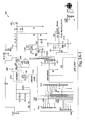
- FIG. 1 is a block schematic diagram of a radiation system.
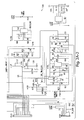
- FIG. 2A is a circuit schematic diagram of an implementation of a current regulation unit included in the radiation system of FIG. 1 .
- FIG. 2B is an enlarged circuit schematic diagram of the current regulator analog circuit shown in FIG. 2A .
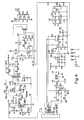
- FIG. 3 is a circuit schematic diagram of a load driver unit such as the one shown in FIG. 1 .
- FIG. 4 is a circuit schematic diagram of a simmer board module.
- FIG. 5 is a flowchart of a procedure to regulate the current level delivered to a high current radiation source.
- a high current radiation system includes a high current radiation source to generate radiation, and an analog circuit to generate, based, at least in part, on an input signal representative of the present current level delivered to the high current radiation source and a user-controlled input representative of a desired current level, an output signal to control the current level to be delivered to the high current radiation source.
- the system further includes a current driver to control the current delivered to the high current radiation source based, at least in part, on the output signal of the analog circuit.
- the analog circuit may include an analog comparator implemented using at least one operational amplifier. The analog circuit may be implemented without any programmable devices.
- the system 100 includes a simmer board 110 to trigger the radiation source (i.e., make it conductive and ready for operation), a current regulation unit 120 to generate control signals to regulate the current provided to a load (e.g., an IPL lamp) and a load driver unit 130 which, in response to the control signals received from the current regulation unit 120, regulates the current flow (i.e., drives the load by, for example, turning on and off a switching device through which current is provided to the load).
- a simmer board 110 to trigger the radiation source (i.e., make it conductive and ready for operation)
- a current regulation unit 120 to generate control signals to regulate the current provided to a load (e.g., an IPL lamp)
- a load driver unit 130 which, in response to the control signals received from the current regulation unit 120, regulates the current flow (i.e., drives the load by, for example, turning on and off a switching device through which current is provided to the load).
- the system 100 further includes a high current radiation source 140 to generate radiation emissions that arc directed to the areas to be treated (e.g., skin tissue of a patient).
- the high current radiation source 140 is an Intense Pulsed Light source.
- a light source may include an incoherent light source such as a gas filled linear flash lamp.
- the spectrum of light emitted by a gas filled linear flash lamp may depend on current density, the type of glass envelope material and gas mixture used in the tube. For large current densities (e.g., 3000 A/Cm 2 or more) the spectrum may be similar to a black body radiation spectrum. Typically, most of the energy is emitted in the 300 to 1300 nm wavelength range.
- IPL source is a Xenon flash lamp that is controlled to generate intense incoherent pulses that have durations of, for example, a few microseconds to a few milliseconds.
- the radiation source may include laser devices configured to operate in either continuous or pulsed mode.
- Suitable laser devices include, for example, Nd:YAG laser devices, Nd:YLF laser devices, Yb:YAG laser devices, etc.
- Other types of radiation sources such as radio frequency sources, ultrasound sources, etc., may also be used.
- the power source 105 may include standard electrical outlets, one or more butteries, an electric generator, etc.
- the current regulation unit 120 is configured to regulate the current/voltage level of the current/voltage provided by the power source 105 based, at least in part, on user-controlled input representative of current level required or desired by the user, and a signal representative of the actual present current/voltage level applied to the radiation source.
- the current regulation unit is further configured, among other things, to generate, based on the aforementioned inputs, a control output signal that regulates (or actuates) the driver unit (which may include one or more switching devices).
- FIG. 2A a circuit schematic diagram of an implementation of the current regulation unit 120 is shown.
- the current regulation unit 120 includes an analog current regulator circuit 210 that receives a user-controlled input representing a desired current that is to be provided to the radiation source and a signal representing the actual present current flowing in the radiation source, and based on those inputs generates a control signal 230 that is used to actuate the driver unit 130 of the system 100.
- the current regulation unit 120 is implemented without using any programmable devices to control/regulate the high current that is provided to the radiation source 140.
- the analog circuit 210 includes, in some embodiments, an amplifier, such as an operational-amplifier-based arrangement, to perform an initial amplification to amplify the user-controlled input signal representative of the current level required to be applied to the radiation source.
- an amplifier such as an operational-amplifier-based arrangement
- the amplifier depicted in FIGS. 2A and 2B is implemented using an operation amplifier 212 (marked U3A).
- the user-controlled input signal is provided at the terminal 214 (marked TP3) in FIG. 2B , and may be generated through a user-interface (e.g., buttons, switches, keypad, etc.) that cause a signal level at a particular voltage range to be produced in response to input from the user.
- a user-interface e.g., buttons, switches, keypad, etc.
- the signal produced at terminal 214 has a level range of 0-3V. This range corresponds to the current range that flows through the radiation source. For example, if the maximum current that may be set to flow through the radiation source is 600A, an input signal of 3V (produced based on user-controlled inputs provided through the user interlace) may represent a desired radiation source current of 600A. Thus, under those circumstances, a signal of 1.5V at the terminal 214 will correspond to a desired current level of 300A.
- the input signal representative of the desired current level is provided as input to the amplifier implemented using the operational-amplifier 212.
- the input signal representative of the current flowing through the radiation source i.e., the actual current level
- the signal representative of the actual current of the radiation source may have a signal range of 0-8 V (e.g., 8V may correspond to 600A).
- the amplifier implemented using the operational amplifier 212 effectively transforms the input signal (provided to it at the positive terminal 211 of the amplifier 212) to a level range that is in substantially the same level range as the signal representative of the actual current level of the radiation source.
- the operational amplifier 212 is arranged in a non-inverting configuration such that the input terminal 214 is electrically coupled to the positive terminal of the operational amplifier 212.
- the operational amplifier 212 has a gain of approximately 2.667 V/V.
- Suitable operational amplifiers that may be used in the implementation of the amplifier stage of the current regulation circuit (as well as throughout the implementation described herein) include commercially available amplifiers like those manufactured by, for example, Analog Devices, Texas Instruments, Liner Technology, etc. As shown in FIG. 2B , in some embodiments, the operational-amplifiers used include Analog Devices AD823AN operational amplifiers.
- the amplified output of the user-controlled input signal (e.g., based on user-specified input) is electrically communicated to a comparator implemented, for example, using an operational amplifier 220 (marked U3B).
- the comparator is configured to generate, based, at least in part, on the amplified signal outputted by the operational amplifier 212 and based on the input signal representative of the present actual current level of the radiation source, an output signal to control the current level to be delivered to the high current radiation source.
- the outputs produced may be constant logical high or logical low voltages (i.e., the output produced by the operational amplifier 220 can be one of two voltage levels).
- the produced output signal of the operational amplifier 220 (e.g., "high” or “low” voltage levels) can then used to actuate a switching device(s).
- a switching device e.g., "high” or “low” voltage levels
- the signal 230 generated by the comparator actuates the load driver unit 130 which acts as a switch to control delivery of current (power) to the radiation source.
- the negative terminal 222 (marked as terminal 6) of the operational amplifier 220 is electrically coupled (via resistor R41 and the connector P977 shown in FIG. 2A ) to the output of a current sensor 240 (shown in FIG. 2A ) such as, for example, an amperemeter.
- the sensor 240 measures the current flowing (directed) through the high current radiation source 140 and generates a signal representative of that measured current.
- the measured signal is converted (nominalized) to a signal in the range of 0-8 V.
- a value of 8V of the normalized signal may represent, for example, a current level of 600A passing through the radiation source.
- the normalization operations may be performed to produce output signal having different ranges (i.e., different from the 0-8V range) and/or with respect to different current ranges corresponding to the currents that may pass through the high current radiation source.
- the operational-ampimer 220 Electrically coupled to the positive terminal 224 (also marked as terminal 5) of the operational-ampimer 220 is the amplified output from the operational amplifier 212 that represents the user-desired current level that should be flowing in the high current radiation source.
- the comparator circuit receives a generally constant user-controlled signal (i.e., constant until such time that the user provides input indicating a different desired current level for the high current radiation source) to cause the current flowing through the high current radiation source to converge to a value substantially equal to the value desired by the user. Specifically, if the actual current level flowing through the high current radiation source, as indicated by the input signal that is electrically coupled to the input terminal 222 of the operational amplifier 220, is below the signal voltage level provided through the input terminal 224, the output of the operational amplifier 220 (i.e., the operation amplifier used to implement the comparator) will go high.
- a generally constant user-controlled signal i.e., constant until such time that the user provides input indicating a different desired current level for the high current radiation source
- the driver unit 130 regulating the flow of current into the high current radiation source will be actuated to cause current to flow to the radiation source 140, thus causing an increase in the current level passing to the radiation source in a particular period of time (e.g., one second) and in effect increasing the effective current level flowing through the radiation source.
- the sensor 240 will generate a signal representative of that current level (which is now higher than what the desired level is).
- the signal level at the negative terminal 222 will be higher than the signal level at the terminal 224 of the operational amplifier 220. Consequently, the output of the operational amplifier 220 will be set to a logical low output (e.g., 0V).
- the actuating signal provided to the driver 130 including, e.g., an actuation circuit arrangement 310 shown in FIG.
- the switching device e.g., an IGBT transistor
- the switching device e.g., an IGBT transistor
- the current level passing through the radiation source in a given time period will begin to decrease, causing the current level to converge back to the desired current level.
- the comparator will again generate a logical high level signal, causing the driver unit 130 (or any other implemented switching device to drive the radiation source) to be actuated such that current is again provided to the radiation source.
- a resistor R37 may be electrically coupled between the positive terminal 224 of the comparator (implemented using the operational amplifier 220) and its output terminal (marked as terminal 7).
- the value of the resistor R37 may be used to control the comparator's hysteresis behavior to prevent excessive changes in the state (High/Low) of the comparator. Implementation of hysteresis behavior in the comparator may result in controlled deviations of the current flowing in the radiation source.
- the value of the resistor in the positive feedback path of the comparator can be selected so that the resultant current deviations from the target current is ⁇ 50A (e.g., if the target current is 500A, the resistor R37 can be selected to have a value that will result in hysteresis behavior causing current swings of between 450-550A).
- Implementation of hysteresis behavior reduces the switching frequency of the switching devices/components (e.g., the IGBT switch) in the implementation depicted in FIGS. 2-4 .
- a circuit schematic diagram of a load driver unit 130 is shown (a schematic representation of the driver unit 130 relative to the load 140 and the circuit schematic of the current regulation unit 120 also appears in FIG. 2A ).
- the driver unit 130 is implemented using an Insulated-Gate Bi-Polar Transistor, or IGBT 360, that electrically couples the power source 105 to the radiation source.
- IGBT 360 Insulated-Gate Bi-Polar Transistor
- Other types of high-power switching devices e.g., high power transistors
- the IGBT is controlled (actuated) using the actuation circuit arrangement 310.
- the actuation circuit receives the controlled signal 230 (or some filtered/attenuated version thereof) that is coupled to the driver unit 130 via the pin 3 of a connector 302 (also marked as component P961).
- the signal 230 actuates the actuation circuit arrangement 310 which in turn actuates the IGBT to close the IGBT (i.e., make it conductive to thus enable power transfer) or open the IGBT (i.e., make it non-conductive to disable power transfer).
- the actuation circuit arrangement 310 may include a gate driver optocoupler 312, such as an HCPL3101 gate optocoupler, to receive the control signal from the current regulator (e.g., the control signal 230) and, based on the received signal, drive the IGBT accordingly.
- the gate driver 312 interfaces between the received signal and the IGBT to generate the actuation signals needed to drive the IGBT in accordance with the control signal 230.
- Electrically coupled to the gate driver 312 are an nFET transistor 314 (i.e., an channel transistor, marked as Q1) connected at its drain and source to the respective drain and source of a pFET transistor 316 (i.e., a p-channel FET transistor, marked as Q2).
- the gate driver 312 When a logical high signal is applied hy the gate driver 312 (i.e., when the gate driver 312 is actuated by a high-signal from the analog-based regulator circuit) to the gate of the transistor 314, the nFET transistor will become conductive, thus coupling the +15V source to the GATE terminal 332 that is coupled (in operation) to the gate of the IGET (the GATE terminal will be at +15 relative to the EMITTER terminal 334). This will cause the IGBT to become conductive and enable high current to flow through the power IGBT transistor to the radiation source 140. During this time, the pFET transistor will be open (i.e., non-conductive).
- the gate driver 312 will generate, in response, a negative driving signal to cause the transistor 316 to become conductive, while causing the transistor 314 to be non-cnnductive, thus electrically coupling the -15V source 322 to the GATE terminal 332. This, in turn, will cause the IGBT power transistor to effectively be switched off, thus preventing high current from flowing to the radiation source.
- FIG. 3 Also shown in FIG. 3 is a snubber circuit 340 configured to provide electrical protection from overload and/or surge conditions, A schematic representation of the snubber circuit 340 electrically connected to the radiation source 140 also appears in the circuit schematic of FIG. 2A depicting, among other things, the current regulation unit 120.
- the simmer board module is configured to trigger the radiation source by providing it, for example, with low standby current that is sufficient to get the radiation source in condition to perform for radiation emission that is subsequently caused by directing high currents through the radiation source.
- the radiation source includes a Xenon flash lamp
- the simmer board regulates and causes low current to be directed through the Xenon lamp to thus cause the Xenon-based gas mixture within the flash-lamp's tube to become ionized (which decreases the resistance of the gas mixture) and to thus enable high current to travel through the tube.
- the simmer board includes a flyback converter circuit (comprising the Pulse Width Modulator marked U1 and the transistor Q1) configured to generate a high voltage pulse (e.g., 1600V) to cause an initial spark that is applied to the radiation source, e.g., the IPL source, to cause it to become conductive,
- a high voltage pulse e.g. 1600V
- low current e.g. 300-400 mili-ampers
- an output signal to control the current delivered to the radiation source is generated 510 by an analog circuit (e.g., a circuit implemented using one or more operational amplifiers).
- the analog circuit does not include, for example, any programmable devices/components.
- the output control signal is generated based on, at least in part, an input signal representative of the present current level of the high current radiation source and a user-controlled input representative of the desired current level.
- the analog circuit used to generate the output control circuit may be similar to the implementation depicted in FIGS. 2A and 2B .
- the current level delivered to the high current radiation source is controlled 520.
- this may include actuating a power transistor (such as an IGBT device) using the control output signal generated by the analog circuit to enable or disable the flow of current through the power transistor to the high current radiation source.
- a power transistor such as an IGBT device
Landscapes
- Continuous-Control Power Sources That Use Transistors (AREA)
- Radiation-Therapy Devices (AREA)
Applications Claiming Priority (1)
| Application Number | Priority Date | Filing Date | Title |
|---|---|---|---|
| US12/409,274 US7961767B2 (en) | 2009-03-23 | 2009-03-23 | System and method to regulate high current radiation sources |
Publications (2)
| Publication Number | Publication Date |
|---|---|
| EP2234461A2 true EP2234461A2 (fr) | 2010-09-29 |
| EP2234461A3 EP2234461A3 (fr) | 2012-04-04 |
Family
ID=42342674
Family Applications (1)
| Application Number | Title | Priority Date | Filing Date |
|---|---|---|---|
| EP10003081A Ceased EP2234461A3 (fr) | 2009-03-23 | 2010-03-23 | Système et procédé pour réguler les sources de radiation à courant élevé |
Country Status (2)
| Country | Link |
|---|---|
| US (3) | US7961767B2 (fr) |
| EP (1) | EP2234461A3 (fr) |
Families Citing this family (1)
| Publication number | Priority date | Publication date | Assignee | Title |
|---|---|---|---|---|
| US7961767B2 (en) | 2009-03-23 | 2011-06-14 | Lumenis Ltd. | System and method to regulate high current radiation sources |
Citations (4)
| Publication number | Priority date | Publication date | Assignee | Title |
|---|---|---|---|---|
| US4814966A (en) * | 1985-07-11 | 1989-03-21 | Spectra-Physics, Inc. | Shunt switched resistor regulator with diode snubber |
| US5626631A (en) | 1992-10-20 | 1997-05-06 | Esc Medical Systems Ltd. | Method and apparatus for therapeutic electromagnetic treatment |
| EP0828342A2 (fr) * | 1996-09-06 | 1998-03-11 | Mitsubishi Denki Kabushiki Kaisha | Bloc d'alimentation en puissance impulsionnelle |
| US7108689B2 (en) | 1992-10-20 | 2006-09-19 | Lumenis Ltd | Method and apparatus for electromagnetic treatment of the skin, including hair depilation |
Family Cites Families (5)
| Publication number | Priority date | Publication date | Assignee | Title |
|---|---|---|---|---|
| US5048033A (en) * | 1990-09-04 | 1991-09-10 | Coherent, Inc. | Method and apparatus for controlling the power supply of a laser operating in a pulse mode |
| GB9613733D0 (en) * | 1996-07-01 | 1996-09-04 | Spectron Laser Systems Ltd | Irradiating device |
| US6418154B1 (en) * | 1999-06-07 | 2002-07-09 | Coherent, Inc. | Pulsed diode-pumped solid-state laser |
| US7203213B2 (en) * | 2003-12-15 | 2007-04-10 | Micrel, Incorporated | Laser turn-on accelerator independent of bias control loop bandwidth |
| US7961767B2 (en) * | 2009-03-23 | 2011-06-14 | Lumenis Ltd. | System and method to regulate high current radiation sources |
-
2009
- 2009-03-23 US US12/409,274 patent/US7961767B2/en active Active
-
2010
- 2010-03-23 EP EP10003081A patent/EP2234461A3/fr not_active Ceased
-
2011
- 2011-06-01 US US13/150,570 patent/US8184669B2/en not_active Expired - Fee Related
-
2012
- 2012-04-19 US US13/450,594 patent/US8477816B2/en active Active
Patent Citations (4)
| Publication number | Priority date | Publication date | Assignee | Title |
|---|---|---|---|---|
| US4814966A (en) * | 1985-07-11 | 1989-03-21 | Spectra-Physics, Inc. | Shunt switched resistor regulator with diode snubber |
| US5626631A (en) | 1992-10-20 | 1997-05-06 | Esc Medical Systems Ltd. | Method and apparatus for therapeutic electromagnetic treatment |
| US7108689B2 (en) | 1992-10-20 | 2006-09-19 | Lumenis Ltd | Method and apparatus for electromagnetic treatment of the skin, including hair depilation |
| EP0828342A2 (fr) * | 1996-09-06 | 1998-03-11 | Mitsubishi Denki Kabushiki Kaisha | Bloc d'alimentation en puissance impulsionnelle |
Also Published As
| Publication number | Publication date |
|---|---|
| US20100238961A1 (en) | 2010-09-23 |
| US20120201261A1 (en) | 2012-08-09 |
| US7961767B2 (en) | 2011-06-14 |
| US20110228801A1 (en) | 2011-09-22 |
| US8184669B2 (en) | 2012-05-22 |
| US8477816B2 (en) | 2013-07-02 |
| EP2234461A3 (fr) | 2012-04-04 |
Similar Documents
| Publication | Publication Date | Title |
|---|---|---|
| US9877771B2 (en) | System and method for power supply noise reduction | |
| US3923063A (en) | Pulse control circuit for electrosurgical units | |
| US10278771B2 (en) | System and method for delivering 5 high current to electrosurgical device | |
| US4024467A (en) | Method for controlling power during electrosurgery | |
| US7244255B2 (en) | High-frequency surgical generator | |
| JP2656116B2 (ja) | ビーム形電気手術装置 | |
| US6923804B2 (en) | Electrosurgical generator | |
| WO2019095604A1 (fr) | Dispositif de traitement de tumeur par champ électrique à impulsion de forte intensité | |
| US4580562A (en) | Electrosurgical apparatus | |
| JP2007111529A (ja) | 電気外科用発電器において蓄積されたエネルギーを減少させるための回路および方法 | |
| US8184669B2 (en) | System and method to regulate high current radiation sources | |
| IL319700A (en) | Device and method for ablation (burning) by electric pulse field | |
| JP3068052B2 (ja) | 電気外科装置 | |
| US20030108078A1 (en) | Medical laser system | |
| CN102858264B (zh) | 电外科发生器 | |
| JP3046274B2 (ja) | 電気外科器の高電圧電源装置 | |
| US3986033A (en) | Switching device for an X-ray generator comprising a time switch | |
| CN108235526B (zh) | 一种控制电路 | |
| GB2564756A (en) | Surgical assembly and system, and a DC voltage compensation circuit | |
| CN215961821U (zh) | 一种用于强脉冲光输出能量的保护电路 | |
| CN223942591U (zh) | 一种选择电路、发射电源及超声设备 | |
| EP3257461A1 (fr) | Circuit d'amortissement actif variable pour induire une commutation à tension nulle dans un convertisseur de puissance alimenté par courant | |
| JP3676821B2 (ja) | 無線周波数送信機管のカソードパルス変調 | |
| CN117653311A (zh) | 一种高压纳秒电脉冲阻抗匹配方法及消融系统 | |
| JP3201800B2 (ja) | 電気手術器 |
Legal Events
| Date | Code | Title | Description |
|---|---|---|---|
| PUAI | Public reference made under article 153(3) epc to a published international application that has entered the european phase |
Free format text: ORIGINAL CODE: 0009012 |
|
| AK | Designated contracting states |
Kind code of ref document: A2 Designated state(s): AT BE BG CH CY CZ DE DK EE ES FI FR GB GR HR HU IE IS IT LI LT LU LV MC MK MT NL NO PL PT RO SE SI SK SM TR |
|
| AX | Request for extension of the european patent |
Extension state: AL BA ME RS |
|
| PUAL | Search report despatched |
Free format text: ORIGINAL CODE: 0009013 |
|
| AK | Designated contracting states |
Kind code of ref document: A3 Designated state(s): AT BE BG CH CY CZ DE DK EE ES FI FR GB GR HR HU IE IS IT LI LT LU LV MC MK MT NL NO PL PT RO SE SI SK SM TR |
|
| AX | Request for extension of the european patent |
Extension state: AL BA ME RS |
|
| RIC1 | Information provided on ipc code assigned before grant |
Ipc: H05B 41/34 20060101ALI20120301BHEP Ipc: H05B 41/30 20060101AFI20120301BHEP |
|
| 17P | Request for examination filed |
Effective date: 20121003 |
|
| 17Q | First examination report despatched |
Effective date: 20121023 |
|
| STAA | Information on the status of an ep patent application or granted ep patent |
Free format text: STATUS: THE APPLICATION HAS BEEN REFUSED |
|
| 18R | Application refused |
Effective date: 20150312 |