EP2234561B1 - Interface entre tête et manche de brosse pour brosse à dents électrique - Google Patents
Interface entre tête et manche de brosse pour brosse à dents électrique Download PDFInfo
- Publication number
- EP2234561B1 EP2234561B1 EP08862717A EP08862717A EP2234561B1 EP 2234561 B1 EP2234561 B1 EP 2234561B1 EP 08862717 A EP08862717 A EP 08862717A EP 08862717 A EP08862717 A EP 08862717A EP 2234561 B1 EP2234561 B1 EP 2234561B1
- Authority
- EP
- European Patent Office
- Prior art keywords
- driveshaft
- interface
- coupling member
- brushhead
- coupling
- Prior art date
- Legal status (The legal status is an assumption and is not a legal conclusion. Google has not performed a legal analysis and makes no representation as to the accuracy of the status listed.)
- Active
Links
Images




Classifications
-
- A—HUMAN NECESSITIES
- A61—MEDICAL OR VETERINARY SCIENCE; HYGIENE
- A61C—DENTISTRY; APPARATUS OR METHODS FOR ORAL OR DENTAL HYGIENE
- A61C17/00—Devices for cleaning, polishing, rinsing or drying teeth, teeth cavities or prostheses; Saliva removers; Dental appliances for receiving spittle
- A61C17/16—Power-driven cleaning or polishing devices
- A61C17/22—Power-driven cleaning or polishing devices with brushes, cushions, cups, or the like
- A61C17/32—Power-driven cleaning or polishing devices with brushes, cushions, cups, or the like reciprocating or oscillating
- A61C17/34—Power-driven cleaning or polishing devices with brushes, cushions, cups, or the like reciprocating or oscillating driven by electric motor
-
- A—HUMAN NECESSITIES
- A61—MEDICAL OR VETERINARY SCIENCE; HYGIENE
- A61C—DENTISTRY; APPARATUS OR METHODS FOR ORAL OR DENTAL HYGIENE
- A61C17/00—Devices for cleaning, polishing, rinsing or drying teeth, teeth cavities or prostheses; Saliva removers; Dental appliances for receiving spittle
- A61C17/16—Power-driven cleaning or polishing devices
- A61C17/22—Power-driven cleaning or polishing devices with brushes, cushions, cups, or the like
- A61C17/222—Brush body details, e.g. the shape thereof or connection to handle
-
- A—HUMAN NECESSITIES
- A61—MEDICAL OR VETERINARY SCIENCE; HYGIENE
- A61C—DENTISTRY; APPARATUS OR METHODS FOR ORAL OR DENTAL HYGIENE
- A61C2201/00—Material properties
- A61C2201/002—Material properties using colour effect, e.g. for identification purposes
Definitions
- This invention relates generally to handle/brushhead interface arrangements for power toothbrushes, and more specifically concerns such an interface in which the torque transfer function and axial retention function of the brushhead relative to the toothbrush driveshaft is accomplished by a single spring and coupling combination.
- a driveshaft driven rotationally or through a selected angle of oscillation, extends from a handle portion of the toothbrush, with the drive mechanism being contained within the handle portion.
- a removable brushhead assembly fits onto the extending driveshaft.
- the brushhead assembly includes a coupling member, which fits into an arm portion of the brushhead assembly. At the distal end of the arm portion is a brush member for cleaning teeth.
- the driveshaft extends into and securely mates with the coupling member.
- the structural interaction between the drive shaft and the coupling member must be such as to reliably transfer the torque of the moving driveshaft to the brushhead and to maintain the torque transfer under load.
- the load refers to a combination of the torque created by the inertial mass of the oscillating brushhead and the forces created by the interaction with the tissues and other elements of the user's mouth.
- the structural interaction must also be sufficient to hold the brushhead on the driveshaft, which is referred to as axial retention, during operation of the toothbrush, while also permitting the brushhead to be conveniently removed by the user.
- Axial retention can be a challenging aspect of such an arrangement if the brushhead is to be removed regularly for cleaning or other purposes.
- the arrangement must be such that the functions of torque transfer and axial retention are not degraded even after the brushhead assembly has been removed numerous, perhaps hundreds, of times during the lifetime of the brushhead assembly.
- a brushhead/handle interface for a power toothbrush comprising: a brushhead assembly having a brush member at one end thereof for cleaning teeth; a driveshaft extending from a handle portion of the toothbrush and having one or more contact regions in which are located interface surfaces; a coupling member positioned at the other end of the brushhead assembly for receiving the driveshaft, wherein the coupling member includes one or more interface portions which come into physical contact with said interface surfaces of the driveshaft when the driveshaft is inserted into the coupling member; and a spring member positioned so as to exert a force against the coupling member large enough that the physical contact between said interface portion or portions of the coupling member and said one or more contact regions of the driveshaft is sufficient to maintain axial retention of the brushhead assembly on the driveshaft during operation of the toothbrush, while permitting a user to remove the brushhead assembly from the driveshaft when the toothbrush is not operating.
- the present arrangement is capable of reliably providing both the torque transfer and the axial retention functions, while permitting a large number of removals of the brushhead assembly from the driveshaft.
- a brushhead / handle interface for a power toothbrush comprising:
- Figure 1 shows a toothbrush 10 which includes a handle portion 12 with a drive assembly which includes an extending driveshaft 14, the driveshaft driven by a motor (not shown) positioned within handle 12.
- the motor moves the driveshaft in an oscillating manner through a selected angle.
- the motor is controlled by a user-operated on/off switch 16.
- Removably mounted on driveshaft 14 is a brushhead assembly 20.
- the brushhead assembly 20 includes a coupling assembly 22 which fits snugly into and is captured by an arm portion 24 of the brushhead assembly. Positioned on a distal end of the arm portion is a conventional brush member 26 which cleans the teeth. In operation, brush member 26 rotates/oscillates back and forth through a selected angle to accomplish the desired cleansing.
- the coupling assembly may further include a ring 28 at the proximal end 30 of the coupling assembly. The ring can be different colors to identify the user of the brushhead assembly.
- the coupling assembly further includes a spring member 34 which fits around a portion of the body of the coupling assembly 22.
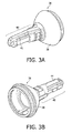
- the coupling assembly is shown in more detail in Figures 3A and 3B . It includes a base portion 36, the lower end of which may be configured to receive ring 28. Forward of ring 28 is an inwardly angled surface portion 38, substantially cone-shaped. Forwardly of the angled portion 38 is a coupling body portion 40.
- the body portion 40 includes an internal axial opening which receives the driveshaft 14. Along one side of the body portion 40 is a rib 41 which extends for substantially the length of the body portion, the rib fitting snugly into a mating slot in arm portion 24. The rib 41 locates and maintains the physical relationship between the coupling assembly and the arm portion 24.
- coupling strip 44 On the opposite side of the body portion from rib 41 is a coupling strip 44. This is shown in both Figures 3B and Figure 5 .
- coupling strip 44 is fixedly mounted to the body portion 40 at the opposing ends of the strip and is free to flex to some extent between its two ends.
- the body portion 40 is made from acetal which permits flexing of the coupling strip to occur, while being tough enough to resist abrasion and compression deformation or creep during the life of the brushhead.
- Coupling strip 44 is approximately 0.6 mm long and approximately 0.3 mm wide. It is approximately 0.80 mm thick, except for a first interface contact member portion 46, which is approximately 1.323 mm thick.
- the first interface contact member 46 is a bulge or block which extends inwardly from coupling strip 44 approximately 0.16 mm, sufficient to make a significant physical contact with the inserted driveshaft 14.
- the first interface contact member could be located on spring member 34, in which case the coupling strip 44 could be eliminated.
- spring member 34 is positioned around a part of the body portion 40 of the coupling assembly.
- Spring member 34 is shown in more detail in Figure 4 .
- the spring member is, in the embodiment shown, an angled C-shaped configuration, although it could be other configurations, including an oval or a closed arrangement.
- the spring could also be a leaf spring or a coil spring.
- Spring member 34 is arranged and configured to provide an inwardly directed force against the body portion of the coupling assembly with sufficient frictional and physical contact between the body portion and the driveshaft to produce the desired torque transfer as well as axial retention. In the embodiment shown, this force is in the range of 30-60 newtons, preferably approximately 50 newtons.
- the body portion of the coupling assembly and the extending portion of the driveshaft can be of various configurations to achieve this desired functional result.
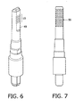
- a contact portion 49 on the driveshaft includes a plurality of grooves 50 which extend laterally across the contact portion, which is flat.
- the grooves are approximately 0.10 mm deep, have a generally curved configuration, with a distance of 0.65 mm center to center.
- the physical interaction between the grooves 50 in the first contact portion of the driveshaft and the first interface contact member 46 produces a good torque transfer between the driveshaft and the brushhead assembly, as well as sufficient axial retention to maintain the brushhead assembly on the driveshaft during operation of the toothbrush.
- the axial retention is also such as to permit the user to conveniently remove the brushhead from the driveshaft for cleaning and the like, without degrading the torque transfer and axial retention functions.
- Figure 7 shows another embodiment of a driveshaft contact portion 55.
- contact portion 55 has been roughened, such as by sandblasting or the like.
- the surface finish is 0.80 ⁇ meters or rougher, e.g. up to 1.6 ⁇ meters.
- This driveshaft surface, with the interface contact member 46 of the coupling member described above, is also sufficient to accomplish the desired torque transfer and axial retention functions.
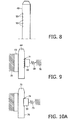
- Figure 9 shows a simplified representation of the embodiment of Figures 5 , 6 and 8 . It includes a grooved driveshaft 64, an interface contact member 66 of a coupling member and a representation of the spring function at 68. Portions 70-70 refer generally to the brushhead assembly arm, in which the coupling assembly is mounted. Portion 69 refers to the part of the coupling member on the opposite side of the driveshaft from the interface contact member. In this embodiment, the spring pressure is against the interface contact member, which bears directly against the grooves 71 on the driveshaft 64.
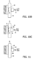
- Figures 10A-10C show another embodiment in which driveshaft 72 has a slot in a surface thereof, the slot being sufficiently large to accommodate an interface contact member portion of the coupling assembly.
- Each of the embodiments of Figures 10A-10C includes a spring function 73.
- Figure 10A shows a slot 74 in surface 76 of driveshaft 72 and an interface contact member 77 fitting therein.
- Figure 10B shows a slot 80 in surface 81 of the driveshaft opposite from spring function 73 and an interface contact member 75 which extends from coupling assembly on the opposite side from spring function73 into slot 80.
- Figure 10C shows a driveshaft 72 with slots 86 and 88 on both (opposing) sides of the driveshaft, into which are fitted a first interface contact member 90 on the same side of the driveshaft as spring function 73, and a second interface contact member 92 extending from coupling assembly 93 on the opposite side of the driveshaft from spring function 73.
- FIG 11 shows a further embodiment, in which a driveshaft 96 includes a protrusion 98 from surface 99 thereof, on the spring function side of the driveshaft.
- Interface contact member 100 is positioned adjacent to one end 102 of the driveshaft protrusion 98.
- FIGs 12A-12C show additional embodiments in which protrusions are located on one or both sides of the driveshaft, with the interface contact members having a slot into which the protrusions fit.
- driveshaft 104 includes a protrusion 106 on the spring function side of the driveshaft.
- Interface contact member 108 includes a slot 110 into which protrusion 106 fits.
- Figure 12B shows a driveshaft 112 with a protrusion 118 on the side opposite from the spring function side. Protrusion 118 fits into a slot 114 in the coupling assembly on the side opposite from the spring function side of the coupling assembly.
- Figure 12C shows a driveshaft 124 having protrusions 132 and 136 on opposing sides of the driveshaft.
- interface contact member 130 On the spring side of the driveshaft is interface contact member 130, which has a slot 126 therein to receive protrusion 132, while in the opposing side of the coupling assembly is a slot 128 into which fits protrusion 136.
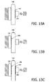
- Figures 13A-13C show further embodiments with roughened surfaces on contact portions of the driveshaft, like that shown in Figure 7 .
- Figure 13A includes a driveshaft 140 having a roughened surface region 142 on the spring function side of the driveshaft. Interface contact member 144 makes sufficient physical contact with the roughened surface 142 to accomplish the desired functions.
- Figure 13B shows a driveshaft 146 with a roughened surface region 148 on the side of the driveshaft opposite from the spring function. Coupling assembly portion 150 on the opposite side of the driveshaft makes the required physical contact with the roughened region 148.
- Figure 13C shows a driveshaft 152 with roughened surface regions 154 and 156 on opposite sides of the driveshaft.
- Interface contact member 160 engages roughened surface region 154, while the surface of coupling assembly portion 164 on the opposite side from interface member 160 engages roughened surface region 156.
Landscapes
- Health & Medical Sciences (AREA)
- Dentistry (AREA)
- Epidemiology (AREA)
- Life Sciences & Earth Sciences (AREA)
- Animal Behavior & Ethology (AREA)
- General Health & Medical Sciences (AREA)
- Public Health (AREA)
- Veterinary Medicine (AREA)
- Brushes (AREA)
Abstract
Claims (13)
- Interface tête de brosse/manche pour une brosse à dents électrique (10), comprenant :un ensemble tête de brosse (20) comportant un élément brosse (26) à une extrémité de celui-ci pour nettoyer les dents ;un arbre d'entraînement (14) s'étendant à partir d'une partie de poignée (12) de la brosse à dents (10), entraîné de sorte qu'il oscille à travers un angle de rotation sélectionné, l'arbre d'entraînement (14) comportant une ou plusieurs régions de contact (49) dans lesquelles sont situées des surfaces d'interface (50) ;un élément d'accouplement (22) positionné à l'autre extrémité de l'ensemble tête de brosse (20) et comportant une partie de corps (40) avec une ouverture axiale interne pour recevoir l'arbre d'entraînement (14), dans laquelle l'élément d'accouplement (22) comprend une ou plusieurs parties d'interface (46) qui entrent en contact physique avec lesdites surfaces d'interface (50) de l'arbre d'entraînement (14) lorsque l'arbre d'entraînement (14) est inséré dans l'élément d'accouplement (22) ; etun élément ressort (34) positionné autour d'une partie de la partie de corps (40) afin d'exercer une force contre l'élément d'accouplement (22) suffisamment importante pour que le contact physique entre ladite partie ou lesdites parties d'interface (46) de l'élément d'accouplement (22) et ladite ou lesdites régions de contact (50) de l'arbre d'entraînement (14) soit suffisant pour produire un transfert de couple fiable entre l'arbre d'entraînement (14) et l'ensemble tête de brosse (20) et pour maintenir une retenue axiale de l'ensemble tête de brosse (20) sur l'arbre d'entraînement (14) au cours du fonctionnement de la brosse à dents (10), tout en permettant à un utilisateur de retirer l'ensemble tête de brosse (20) à partir de l'arbre d'entraînement (14) lorsque la brosse à dents (10) ne fonctionne pas.
- Interface selon la revendication 1, dans laquelle l'élément d'accouplement (22) comprend un élément bande d'accouplement (44) monté de façon fixe sur la partie de corps (40) de l'élément d'accouplement (22) aux extrémités opposées de l'élément bande (44) et est libre de se fléchir dans une certaine mesure entre ses deux extrémités afin de permettre le mouvement de l'élément bande (44) entre celles-ci, et dans laquelle l'élément bande d'accouplement (44) comprend une partie d'interface (46), s'étendant vers l'intérieur dans la direction de l'arbre d'entraînement (14), entraînant un contact physique entre ladite partie d'interface (46) et une surface d'interface (50) de l'arbre d'entraînement (14) lorsque l'arbre d'entraînement (14) est reçu dans l'ensemble tête de brosse (20).
- Interface selon la revendication 1, dans laquelle l'utilisateur est capable de retirer l'ensemble tête de brosse (20) une pluralité importante de fois sans dégrader les capacités de transfert de couple et de retenue axiale.
- Interface selon la revendication 1, dans laquelle l'élément ressort (34) présente une forme sensiblement de C en section transversale.
- Interface selon la revendication 2, dans laquelle les surfaces d'interface (50) de l'arbre d'entraînement (14) comprennent une pluralité de rainures latérales (50) qui s'étendent sur la région de contact de l'arbre d'entraînement (14) et dans laquelle la partie d'interface (46) de l'élément d'accouplement (22) est sensiblement plus importante qu'une quelconque des rainures (50).
- Interface selon la revendication 2, dans laquelle les surfaces d'interface de l'arbre d'entraînement (72) comprennent une fente (74), et dans laquelle une partie d'interface (77) de l'élément d'accouplement est configurée pour se loger à l'intérieur de la fente (74).
- Interface selon la revendication 6, dans laquelle les surfaces d'interface de l'arbre d'entraînement (72) comprennent une fente (80) sur un côté de l'arbre d'entraînement opposé à un côté contre lequel la force de ressort est exercée, et dans laquelle une des parties d'interface (75) de l'élément d'accouplement comprend une protubérance configurée pour aller à l'intérieur de ladite fente (80).
- Interface selon la revendication 6, dans laquelle les surfaces d'interface de l'arbre d'entraînement (72) comprennent des fentes (86, 88) dans des côtés opposés de celles-ci et dans laquelle les parties d'interface (90, 92) de l'élément d'accouplement comprennent des protubérances configurées pour aller à l'intérieur des fentes (86, 88).
- Interface selon la revendication 1, dans laquelle les surfaces d'interface de l'arbre d'entraînement (96) comprennent une protubérance (98) et dans laquelle une partie d'interface (100) de l'élément d'accouplement se loge contre l'arbre d'entraînement (96) de façon adjacente à la protubérance (98).
- Interface selon la revendication 1, dans laquelle les surfaces d'interface de l'arbre d'entraînement (104) comprennent au moins une protubérance (106) s'étendant à partir de celles-ci, et dans laquelle les parties d'interface de l'élément d'accouplement comprennent une fente (110) dans laquelle l'arbre d'entraînement protubérance se loge.
- Interface selon la revendication 10, dans laquelle les surfaces d'interface de l'arbre d'entraînement (124) comprennent des protubérances (132, 136) sur des côtés opposés de celles-ci, et dans laquelle les parties d'interface de l'élément d'accouplement comprennent des fentes (126, 128) qui reçoivent les protubérances (132, 136).
- Interface selon la revendication 1, dans laquelle les surfaces d'interface de l'arbre d'entraînement (140) comprennent au moins une région rugosifiée (142), et dans laquelle une partie d'interface (144) de l'élément d'accouplement réalise ledit contact physique avec la région rugosifiée (142).
- Interface selon la revendication 12, dans laquelle les surfaces d'interface de l'arbre d'entraînement (152) comprennent des régions rugosifiées (154, 156) sur des côtés opposés de l'arbre d'entraînement (152), et dans laquelle les parties d'interface (160, 164) de l'élément d'accouplement réalisent ledit contact physique avec les régions rugosifiées (154, 156).
Applications Claiming Priority (2)
| Application Number | Priority Date | Filing Date | Title |
|---|---|---|---|
| US1449607P | 2007-12-18 | 2007-12-18 | |
| PCT/IB2008/055168 WO2009077922A1 (fr) | 2007-12-18 | 2008-12-09 | Interface entre tête et manche de brosse pour brosse à dents électrique |
Publications (2)
| Publication Number | Publication Date |
|---|---|
| EP2234561A1 EP2234561A1 (fr) | 2010-10-06 |
| EP2234561B1 true EP2234561B1 (fr) | 2012-08-08 |
Family
ID=40601374
Family Applications (1)
| Application Number | Title | Priority Date | Filing Date |
|---|---|---|---|
| EP08862717A Active EP2234561B1 (fr) | 2007-12-18 | 2008-12-09 | Interface entre tête et manche de brosse pour brosse à dents électrique |
Country Status (10)
| Country | Link |
|---|---|
| US (1) | US8782841B2 (fr) |
| EP (1) | EP2234561B1 (fr) |
| JP (1) | JP5734663B2 (fr) |
| KR (1) | KR101537530B1 (fr) |
| CN (1) | CN101902986B (fr) |
| BR (1) | BRPI0820849A2 (fr) |
| CA (1) | CA2709756C (fr) |
| ES (1) | ES2391921T3 (fr) |
| RU (1) | RU2489117C2 (fr) |
| WO (1) | WO2009077922A1 (fr) |
Cited By (4)
| Publication number | Priority date | Publication date | Assignee | Title |
|---|---|---|---|---|
| EP3470015A1 (fr) | 2017-10-11 | 2019-04-17 | Trisa Holding AG | Brosse enfichable, partie poignée de la brosse à dents électrique et brosse à dents électrique dotée d'une partie poignée de la brosse électrique et la brosse enfichable |
| CN109661214A (zh) * | 2016-08-19 | 2019-04-19 | 皇家飞利浦有限公司 | 用于检测附件头安装和拆卸的方法 |
| EP3865088A1 (fr) | 2020-02-17 | 2021-08-18 | Trisa Holding AG | Dispositif de brosse enfichable |
| EP4069137B1 (fr) * | 2019-12-03 | 2024-04-03 | Koninklijke Philips N.V. | Tête de brosse pour un dispositif de soins buccaux et son procédé d'assemblage |
Families Citing this family (58)
| Publication number | Priority date | Publication date | Assignee | Title |
|---|---|---|---|---|
| ES2562793T3 (es) * | 2009-12-16 | 2016-03-08 | Braun Gmbh | Sección de limpieza bucal de un dispositivo de limpieza bucal y dispositivo de limpieza bucal |
| EP2603165B1 (fr) * | 2010-08-09 | 2018-02-21 | Koninklijke Philips N.V. | Arbre d'entraînement flexible pour appareil de soins personnels entraîné par le poids excentrique |
| US8990991B2 (en) * | 2010-12-20 | 2015-03-31 | Koninklijke Philips N.V. | Power toothbrush and brushhead therefor, with multiple motion brush member |
| WO2013061219A1 (fr) * | 2011-10-25 | 2013-05-02 | Koninklijke Philips Electronics N.V. | Tête de brosse pour une brosse à dents électrique avec un ensemble de raccordement à deux positions |
| DE102012006723B4 (de) | 2012-04-02 | 2020-06-18 | M + C Schiffer Gmbh | Bürstenkopfaufsatz |
| US9237943B2 (en) | 2013-09-24 | 2016-01-19 | M+C Schiffer Gmbh | Brush head attachment |
| TR201815789T4 (tr) * | 2013-10-25 | 2019-01-21 | Koninklijke Philips Nv | Bir elektrikli diş fırçası tutma yeri için eklenti ve eklemenin yöntemi. |
| USD769626S1 (en) | 2013-12-19 | 2016-10-25 | Colgate-Palmolive Company | Refill head for electric toothbrush |
| USD776435S1 (en) | 2013-12-19 | 2017-01-17 | Colgate-Palmolive Company | Head portion of a toothbrush |
| USD766581S1 (en) | 2013-12-19 | 2016-09-20 | Colgate-Palmolive Company | Electric toothbrush handle |
| RU2718317C2 (ru) * | 2015-05-14 | 2020-04-01 | Конинклейке Филипс Н.В. | Насадочная конструкция для электрической зубной щетки, электрическая зубная щетка и рукоятка для неё, способ фиксации насадочной конструкции к рукоятке электрической зубной щетки |
| USD790860S1 (en) | 2015-11-25 | 2017-07-04 | Colgate-Palmolive Company | Electric toothbrush brush head |
| USD794333S1 (en) | 2015-11-25 | 2017-08-15 | Colgate-Palmolive Company | Electric toothbrush brush head |
| US10582990B2 (en) | 2015-11-25 | 2020-03-10 | Shanghai Shift Electronics Co., Ltd. | Head module capable of reciprocal rotation for electric cleaning apparatus |
| WO2018045194A1 (fr) * | 2016-08-31 | 2018-03-08 | Martell Steffan | Dispositif de massage de tissu |
| CN110167480B (zh) * | 2016-11-03 | 2022-08-02 | 米哈兰·帕帕吉安 | 用于牙刷系统的替换的牙刷刷头组件 |
| US9724180B1 (en) | 2017-01-06 | 2017-08-08 | Harria Investment Group Inc. | Brush head for electric toothbrush |
| USD830699S1 (en) | 2017-02-03 | 2018-10-16 | Harria Investment Group Ltd. | Brush head for an electric toothbrush |
| USD838990S1 (en) | 2017-05-11 | 2019-01-29 | Harria Investment Group Ltd | Brush head for an electric toothbrush |
| CN109223230B (zh) * | 2017-07-11 | 2020-09-25 | Js控股股份有限公司 | 用于电动牙刷的可移除的刷头 |
| USD858105S1 (en) | 2017-11-17 | 2019-09-03 | Colgate-Palmolive Company | Oral care implement |
| USD893881S1 (en) | 2017-11-17 | 2020-08-25 | Colgate-Palmolive Company | Oral care apparatus |
| USD858997S1 (en) | 2017-11-17 | 2019-09-10 | Colgate-Palmolive Company | Tracking module for an oral care implement |
| USD869855S1 (en) | 2018-07-24 | 2019-12-17 | Burst.USA Inc. | Toothbrush handle |
| CN109008178A (zh) * | 2018-10-19 | 2018-12-18 | 吴晓旺 | 一种一次性牙刷头 |
| CN110151348B (zh) * | 2019-03-14 | 2024-04-19 | 胡斐凡 | 一种刷头组件及电动牙刷 |
| CN114652476B (zh) * | 2019-04-15 | 2024-11-01 | 广州星际悦动股份有限公司 | 一种用于电动牙刷的刷头和具有其的电动牙刷 |
| US12257118B2 (en) | 2019-05-20 | 2025-03-25 | Braun Gmbh | Bristle driven pulsation |
| US11583061B2 (en) | 2019-10-08 | 2023-02-21 | Ranir, Llc | Attachment portion for an electric toothbrush replacement head |
| US11311096B2 (en) * | 2020-03-18 | 2022-04-26 | Water Pik, Inc. | Brush head for an oral cleansing device |
| US20230149140A1 (en) * | 2020-04-30 | 2023-05-18 | Colgate-Palmolive Company | Oral Care Implement and Refill Head Thereof |
| USD954441S1 (en) | 2020-07-20 | 2022-06-14 | Js Holding Inc. | Brush head for electric toothbrush |
| US12201493B2 (en) | 2020-07-20 | 2025-01-21 | Oralic Supplies Inc. | Structure for coupling toothbrush head to electric toothbrush handle |
| US11071613B1 (en) | 2020-07-20 | 2021-07-27 | Js Holding Inc. | Structure for coupling toothbrush head to electric toothbrush handle |
| US20220022634A1 (en) * | 2020-07-24 | 2022-01-27 | Paris Presents Incorporated | Interchangeable Makeup Brush |
| US10912377B1 (en) | 2020-08-07 | 2021-02-09 | Juan-Yun Kuang | Electric toothbrush brush head and electric toothbrush |
| US11439488B2 (en) | 2020-08-07 | 2022-09-13 | Juan-Yun Kuang | Brushhead for power toothbrush |
| US11666137B2 (en) | 2020-08-07 | 2023-06-06 | Juan-Yun Kuang | Brushhead for power toothbrush |
| US11413126B2 (en) | 2020-08-07 | 2022-08-16 | Juan-Yun Kuang | Brushhead for power toothbrush |
| WO2022028613A1 (fr) * | 2020-08-07 | 2022-02-10 | 匡娟云 | Tête de brosse à dents électrique, et brosse à dents électrique |
| US12458479B2 (en) | 2020-12-10 | 2025-11-04 | Colgate-Palmolive Company | Oral care implement and handle thereof |
| EP4262623B1 (fr) | 2020-12-16 | 2025-06-18 | Koninklijke Philips N.V. | Brosse à dents avec mouvement de tapotement |
| USD971611S1 (en) | 2020-12-17 | 2022-12-06 | Chunyang Liu | Toothbrush head |
| US11096768B1 (en) | 2021-04-16 | 2021-08-24 | Gaosheng Lin | Brush head of an electric toothbrush |
| CN113558804B (zh) * | 2021-07-21 | 2024-08-02 | 深圳市德达兴驱动科技有限公司 | 一种自适应电动牙刷 |
| USD961268S1 (en) | 2021-09-27 | 2022-08-23 | Chaorui Kuang | Toothbrush head |
| USD968813S1 (en) | 2021-09-27 | 2022-11-08 | Chaorui Kuang | Toothbrush head |
| US20230140465A1 (en) * | 2021-11-04 | 2023-05-04 | Water Pik, Inc. | Removable brush head |
| USD1054704S1 (en) | 2022-04-07 | 2024-12-24 | Ting Cao | Brush head |
| USD970895S1 (en) | 2022-04-07 | 2022-11-29 | Shengzhou Li | Toothbrush head |
| USD1041905S1 (en) | 2022-04-07 | 2024-09-17 | Ting Cao | Toothbrush head |
| US12514692B2 (en) * | 2022-04-20 | 2026-01-06 | Oralic Supplies, Inc. | Structure for coupling toothbrush head to electric toothbrush handle |
| DE202022002462U1 (de) | 2022-11-16 | 2023-01-24 | Truemorrow Gmbh | Austauschbarer Aufsatz für elektrische Zahnbürsten |
| CN116421350B (zh) | 2023-05-10 | 2025-10-21 | 宁波赛嘉电器有限公司 | 一种刷头及刷头配件 |
| CN220404177U (zh) | 2023-05-10 | 2024-01-30 | 宁波赛嘉电器有限公司 | 一种刷头 |
| EP4544957A1 (fr) * | 2023-10-25 | 2025-04-30 | The Gillette Company LLC | Connecteur pour un instrument de soins personnels, poignée et instrument de soins personnels |
| EP4544955A1 (fr) * | 2023-10-25 | 2025-04-30 | The Gillette Company LLC | Connecteur pour un instrument de soins personnels, poignée et instrument de soins personnels |
| EP4544956A1 (fr) * | 2023-10-25 | 2025-04-30 | The Gillette Company LLC | Connecteur pour un instrument de soins personnels, poignée et instrument de soins personnels |
Citations (1)
| Publication number | Priority date | Publication date | Assignee | Title |
|---|---|---|---|---|
| WO2002089929A1 (fr) * | 2001-05-07 | 2002-11-14 | The Procter & Gamble Company | Brosse a dents electrique a tete remplaçable et structure de raccordement pour cette derniere |
Family Cites Families (21)
| Publication number | Priority date | Publication date | Assignee | Title |
|---|---|---|---|---|
| US3369265A (en) * | 1966-07-07 | 1968-02-20 | Vistron Corp | Universal toothbrush head |
| CH535042A (de) * | 1971-02-26 | 1973-03-31 | Woog Inst Rech | Steckvorrichtung an einem insbesondere zur Körperpflege dienenden Handgerät zur Befestigung auswechselbarer Behandlungsinstrumente |
| JPH0440905A (ja) * | 1990-06-07 | 1992-02-12 | Hiroshi Fukuba | 電動ローリング歯ブラシ |
| BE1007374A3 (nl) * | 1993-07-30 | 1995-05-30 | Philips Electronics Nv | Tandenborstel. |
| US5697117A (en) * | 1996-01-26 | 1997-12-16 | Teledyne Industries, Inc. | Brush head assembly for motor powered toothbrush |
| DE19627752A1 (de) * | 1996-07-10 | 1998-01-15 | Braun Ag | Elektrische Zahnbürste |
| DE19745876A1 (de) * | 1997-10-17 | 1999-04-22 | Braun Ag | Bürstenteil für eine elektrische Zahnbürste |
| US5842245A (en) * | 1998-05-26 | 1998-12-01 | Pai; Chung-Jen | Electric toothbrush assembly |
| AU6149500A (en) | 1999-06-10 | 2001-01-02 | Gimelli Produktions Ag | Slip-on brush designed for a hand part of an electric toothbrush |
| GB0010115D0 (en) * | 2000-04-27 | 2000-06-14 | Smithkline Beecham Gmbh & Co | Toothbrush |
| JP4436554B2 (ja) * | 2000-09-29 | 2010-03-24 | ピーアイエー株式会社 | ペイントローラ |
| CA2439556C (fr) * | 2001-03-14 | 2011-07-12 | Braun Gmbh | Procede et dispositif pour le brossage des dents |
| US6536066B2 (en) * | 2001-07-25 | 2003-03-25 | Pulse Innovations Inc. | Toothbrush oscillating head |
| TW527913U (en) * | 2002-07-22 | 2003-04-11 | Jeng-Jie Jiang | Structure of brush head for electromotive toothbrush |
| US20040134001A1 (en) * | 2002-09-13 | 2004-07-15 | The Procter & Gamble Company | Toothbrushes with a replaceable head having a threaded connection |
| JP3096312U (ja) * | 2003-03-06 | 2003-09-12 | 正傑 江 | 電動歯ブラシのブラシヘッド |
| JP4773345B2 (ja) * | 2003-06-27 | 2011-09-14 | コーニンクレッカ フィリップス エレクトロニクス エヌ ヴィ | 電動歯ブラシ用のブラシヘッド取付けシステム |
| DE10352993A1 (de) * | 2003-11-13 | 2005-06-16 | Braun Gmbh | Bürstenteil für eine elektrische Zahnbürste |
| GB0329678D0 (en) * | 2003-12-22 | 2004-01-28 | Glaxosmithkline Consumer Healt | Toothbrush |
| JP2006068361A (ja) * | 2004-09-03 | 2006-03-16 | Pigeon Corp | 歯ブラシ |
| JP2006066305A (ja) * | 2004-08-30 | 2006-03-09 | Yokowo Co Ltd | スプリングコネクタ |
-
2008
- 2008-12-09 WO PCT/IB2008/055168 patent/WO2009077922A1/fr not_active Ceased
- 2008-12-09 CN CN200880121230.6A patent/CN101902986B/zh active Active
- 2008-12-09 US US12/374,871 patent/US8782841B2/en active Active
- 2008-12-09 ES ES08862717T patent/ES2391921T3/es active Active
- 2008-12-09 JP JP2010538969A patent/JP5734663B2/ja active Active
- 2008-12-09 KR KR1020107015891A patent/KR101537530B1/ko active Active
- 2008-12-09 RU RU2010129936/14A patent/RU2489117C2/ru active
- 2008-12-09 BR BRPI0820849-2A patent/BRPI0820849A2/pt not_active Application Discontinuation
- 2008-12-09 CA CA2709756A patent/CA2709756C/fr not_active Expired - Fee Related
- 2008-12-09 EP EP08862717A patent/EP2234561B1/fr active Active
Patent Citations (1)
| Publication number | Priority date | Publication date | Assignee | Title |
|---|---|---|---|---|
| WO2002089929A1 (fr) * | 2001-05-07 | 2002-11-14 | The Procter & Gamble Company | Brosse a dents electrique a tete remplaçable et structure de raccordement pour cette derniere |
Cited By (12)
| Publication number | Priority date | Publication date | Assignee | Title |
|---|---|---|---|---|
| CN109661214A (zh) * | 2016-08-19 | 2019-04-19 | 皇家飞利浦有限公司 | 用于检测附件头安装和拆卸的方法 |
| CN109661214B (zh) * | 2016-08-19 | 2021-10-29 | 皇家飞利浦有限公司 | 用于检测附件头安装和拆卸的方法 |
| EP3470015A1 (fr) | 2017-10-11 | 2019-04-17 | Trisa Holding AG | Brosse enfichable, partie poignée de la brosse à dents électrique et brosse à dents électrique dotée d'une partie poignée de la brosse électrique et la brosse enfichable |
| WO2019072994A1 (fr) | 2017-10-11 | 2019-04-18 | Trisa Holding Ag | Brosse amovible, poignée de brosse à dents électrique et brosse à dents électrique pourvue de la poignée de brosse à dents électrique et de la brosse amovible |
| US11666426B2 (en) | 2017-10-11 | 2023-06-06 | Trisa Holding Ag | Brush attachment, electric toothbrush handpiece and electric toothbrush comprising the electric toothbrush handpiece and the brush attachment |
| EP4201376A1 (fr) | 2017-10-11 | 2023-06-28 | Trisa Holding AG | Partie manuelle de brosse à dents électrique et brosse à dents électrique comprenant la partie main de brosse à dents électrique et une brosse enfichable |
| EP4069137B1 (fr) * | 2019-12-03 | 2024-04-03 | Koninklijke Philips N.V. | Tête de brosse pour un dispositif de soins buccaux et son procédé d'assemblage |
| US12370031B2 (en) | 2019-12-03 | 2025-07-29 | Koninklijke Philips N.V. | Brush head for an oral care device and method of assembling the same |
| EP3865088A1 (fr) | 2020-02-17 | 2021-08-18 | Trisa Holding AG | Dispositif de brosse enfichable |
| WO2021165196A2 (fr) | 2020-02-17 | 2021-08-26 | Trisa Holding Ag | Système de brosse à emboîtement |
| EP4494598A2 (fr) | 2020-02-17 | 2025-01-22 | Trisa Holding AG | Dispositif de brosse enfichable |
| US12290419B2 (en) | 2020-02-17 | 2025-05-06 | Trisa Holding Ag | Attachment brush device |
Also Published As
| Publication number | Publication date |
|---|---|
| JP5734663B2 (ja) | 2015-06-17 |
| BRPI0820849A2 (pt) | 2015-06-16 |
| RU2489117C2 (ru) | 2013-08-10 |
| US20100251493A1 (en) | 2010-10-07 |
| KR20100106492A (ko) | 2010-10-01 |
| KR101537530B1 (ko) | 2015-07-21 |
| CA2709756C (fr) | 2015-09-22 |
| CN101902986A (zh) | 2010-12-01 |
| RU2010129936A (ru) | 2012-01-27 |
| ES2391921T3 (es) | 2012-12-03 |
| CA2709756A1 (fr) | 2009-06-25 |
| US8782841B2 (en) | 2014-07-22 |
| WO2009077922A1 (fr) | 2009-06-25 |
| JP2011506028A (ja) | 2011-03-03 |
| CN101902986B (zh) | 2013-11-06 |
| EP2234561A1 (fr) | 2010-10-06 |
Similar Documents
| Publication | Publication Date | Title |
|---|---|---|
| EP2234561B1 (fr) | Interface entre tête et manche de brosse pour brosse à dents électrique | |
| EP4041124B1 (fr) | Tête de brosse à dents de rechange et système de fixation d'une tête de brosse à dents de rechange sur une brosse à dents électrique | |
| US7334283B2 (en) | Power toothbrush | |
| CN101511222B (zh) | 具有多种刷毛状态的牙刷 | |
| CN103269654B (zh) | 用于电动牙刷的具有楔形和弹簧手柄接口的刷头 | |
| CA2498230C (fr) | Brosse a dents electrique | |
| US9597169B2 (en) | Brushhead for a power toothbrush with a two position coupling assembly | |
| EP0651978A1 (fr) | Brosses pour l'hygiène personnelle | |
| CN111372537A (zh) | 用于电动牙刷的替换头 | |
| CN110913794A (zh) | 电动牙刷 | |
| WO2001012099A9 (fr) | Mecanisme de commande d'un appareil de nettoyage dentaire interproximal | |
| US20090019650A1 (en) | Powered toothbrush with flexible head | |
| US20090019649A1 (en) | Electric toothbrush | |
| US20040049867A1 (en) | Electric toothbrush with in-use activation of bristles | |
| EP2468214B1 (fr) | Section de nettoyage d'un dispositif d'hygiène orale électrique | |
| WO2012085844A2 (fr) | Section nettoyante d'un dispositif électrique d'hygiène bucco-dentaire |
Legal Events
| Date | Code | Title | Description |
|---|---|---|---|
| PUAI | Public reference made under article 153(3) epc to a published international application that has entered the european phase |
Free format text: ORIGINAL CODE: 0009012 |
|
| 17P | Request for examination filed |
Effective date: 20100719 |
|
| AK | Designated contracting states |
Kind code of ref document: A1 Designated state(s): AT BE BG CH CY CZ DE DK EE ES FI FR GB GR HR HU IE IS IT LI LT LU LV MC MT NL NO PL PT RO SE SI SK TR |
|
| AX | Request for extension of the european patent |
Extension state: AL BA MK RS |
|
| 17Q | First examination report despatched |
Effective date: 20110209 |
|
| DAX | Request for extension of the european patent (deleted) | ||
| REG | Reference to a national code |
Ref country code: DE Ref legal event code: R079 Ref document number: 602008017913 Country of ref document: DE Free format text: PREVIOUS MAIN CLASS: A61C0017220000 Ipc: A61C0017340000 |
|
| RIC1 | Information provided on ipc code assigned before grant |
Ipc: A61C 17/34 20060101AFI20111219BHEP Ipc: A61C 17/22 20060101ALI20111219BHEP |
|
| GRAP | Despatch of communication of intention to grant a patent |
Free format text: ORIGINAL CODE: EPIDOSNIGR1 |
|
| GRAS | Grant fee paid |
Free format text: ORIGINAL CODE: EPIDOSNIGR3 |
|
| GRAA | (expected) grant |
Free format text: ORIGINAL CODE: 0009210 |
|
| AK | Designated contracting states |
Kind code of ref document: B1 Designated state(s): AT BE BG CH CY CZ DE DK EE ES FI FR GB GR HR HU IE IS IT LI LT LU LV MC MT NL NO PL PT RO SE SI SK TR |
|
| REG | Reference to a national code |
Ref country code: GB Ref legal event code: FG4D |
|
| REG | Reference to a national code |
Ref country code: CH Ref legal event code: EP Ref country code: AT Ref legal event code: REF Ref document number: 569316 Country of ref document: AT Kind code of ref document: T Effective date: 20120815 |
|
| REG | Reference to a national code |
Ref country code: IE Ref legal event code: FG4D |
|
| REG | Reference to a national code |
Ref country code: DE Ref legal event code: R096 Ref document number: 602008017913 Country of ref document: DE Effective date: 20121004 |
|
| REG | Reference to a national code |
Ref country code: ES Ref legal event code: FG2A Ref document number: 2391921 Country of ref document: ES Kind code of ref document: T3 Effective date: 20121203 |
|
| REG | Reference to a national code |
Ref country code: NL Ref legal event code: VDEP Effective date: 20120808 |
|
| REG | Reference to a national code |
Ref country code: AT Ref legal event code: MK05 Ref document number: 569316 Country of ref document: AT Kind code of ref document: T Effective date: 20120808 |
|
| REG | Reference to a national code |
Ref country code: LT Ref legal event code: MG4D Effective date: 20120808 |
|
| PG25 | Lapsed in a contracting state [announced via postgrant information from national office to epo] |
Ref country code: LT Free format text: LAPSE BECAUSE OF FAILURE TO SUBMIT A TRANSLATION OF THE DESCRIPTION OR TO PAY THE FEE WITHIN THE PRESCRIBED TIME-LIMIT Effective date: 20120808 Ref country code: AT Free format text: LAPSE BECAUSE OF FAILURE TO SUBMIT A TRANSLATION OF THE DESCRIPTION OR TO PAY THE FEE WITHIN THE PRESCRIBED TIME-LIMIT Effective date: 20120808 Ref country code: CY Free format text: LAPSE BECAUSE OF FAILURE TO SUBMIT A TRANSLATION OF THE DESCRIPTION OR TO PAY THE FEE WITHIN THE PRESCRIBED TIME-LIMIT Effective date: 20120808 Ref country code: FI Free format text: LAPSE BECAUSE OF FAILURE TO SUBMIT A TRANSLATION OF THE DESCRIPTION OR TO PAY THE FEE WITHIN THE PRESCRIBED TIME-LIMIT Effective date: 20120808 Ref country code: IS Free format text: LAPSE BECAUSE OF FAILURE TO SUBMIT A TRANSLATION OF THE DESCRIPTION OR TO PAY THE FEE WITHIN THE PRESCRIBED TIME-LIMIT Effective date: 20121208 Ref country code: HR Free format text: LAPSE BECAUSE OF FAILURE TO SUBMIT A TRANSLATION OF THE DESCRIPTION OR TO PAY THE FEE WITHIN THE PRESCRIBED TIME-LIMIT Effective date: 20120808 Ref country code: NO Free format text: LAPSE BECAUSE OF FAILURE TO SUBMIT A TRANSLATION OF THE DESCRIPTION OR TO PAY THE FEE WITHIN THE PRESCRIBED TIME-LIMIT Effective date: 20121108 |
|
| PG25 | Lapsed in a contracting state [announced via postgrant information from national office to epo] |
Ref country code: BE Free format text: LAPSE BECAUSE OF FAILURE TO SUBMIT A TRANSLATION OF THE DESCRIPTION OR TO PAY THE FEE WITHIN THE PRESCRIBED TIME-LIMIT Effective date: 20120808 Ref country code: GR Free format text: LAPSE BECAUSE OF FAILURE TO SUBMIT A TRANSLATION OF THE DESCRIPTION OR TO PAY THE FEE WITHIN THE PRESCRIBED TIME-LIMIT Effective date: 20121109 Ref country code: PT Free format text: LAPSE BECAUSE OF FAILURE TO SUBMIT A TRANSLATION OF THE DESCRIPTION OR TO PAY THE FEE WITHIN THE PRESCRIBED TIME-LIMIT Effective date: 20121210 Ref country code: LV Free format text: LAPSE BECAUSE OF FAILURE TO SUBMIT A TRANSLATION OF THE DESCRIPTION OR TO PAY THE FEE WITHIN THE PRESCRIBED TIME-LIMIT Effective date: 20120808 Ref country code: SI Free format text: LAPSE BECAUSE OF FAILURE TO SUBMIT A TRANSLATION OF THE DESCRIPTION OR TO PAY THE FEE WITHIN THE PRESCRIBED TIME-LIMIT Effective date: 20120808 Ref country code: SE Free format text: LAPSE BECAUSE OF FAILURE TO SUBMIT A TRANSLATION OF THE DESCRIPTION OR TO PAY THE FEE WITHIN THE PRESCRIBED TIME-LIMIT Effective date: 20120808 Ref country code: PL Free format text: LAPSE BECAUSE OF FAILURE TO SUBMIT A TRANSLATION OF THE DESCRIPTION OR TO PAY THE FEE WITHIN THE PRESCRIBED TIME-LIMIT Effective date: 20120808 |
|
| PG25 | Lapsed in a contracting state [announced via postgrant information from national office to epo] |
Ref country code: NL Free format text: LAPSE BECAUSE OF FAILURE TO SUBMIT A TRANSLATION OF THE DESCRIPTION OR TO PAY THE FEE WITHIN THE PRESCRIBED TIME-LIMIT Effective date: 20120808 |
|
| PG25 | Lapsed in a contracting state [announced via postgrant information from national office to epo] |
Ref country code: RO Free format text: LAPSE BECAUSE OF FAILURE TO SUBMIT A TRANSLATION OF THE DESCRIPTION OR TO PAY THE FEE WITHIN THE PRESCRIBED TIME-LIMIT Effective date: 20120808 Ref country code: DK Free format text: LAPSE BECAUSE OF FAILURE TO SUBMIT A TRANSLATION OF THE DESCRIPTION OR TO PAY THE FEE WITHIN THE PRESCRIBED TIME-LIMIT Effective date: 20120808 Ref country code: CZ Free format text: LAPSE BECAUSE OF FAILURE TO SUBMIT A TRANSLATION OF THE DESCRIPTION OR TO PAY THE FEE WITHIN THE PRESCRIBED TIME-LIMIT Effective date: 20120808 Ref country code: EE Free format text: LAPSE BECAUSE OF FAILURE TO SUBMIT A TRANSLATION OF THE DESCRIPTION OR TO PAY THE FEE WITHIN THE PRESCRIBED TIME-LIMIT Effective date: 20120808 |
|
| PG25 | Lapsed in a contracting state [announced via postgrant information from national office to epo] |
Ref country code: SK Free format text: LAPSE BECAUSE OF FAILURE TO SUBMIT A TRANSLATION OF THE DESCRIPTION OR TO PAY THE FEE WITHIN THE PRESCRIBED TIME-LIMIT Effective date: 20120808 |
|
| PLBE | No opposition filed within time limit |
Free format text: ORIGINAL CODE: 0009261 |
|
| STAA | Information on the status of an ep patent application or granted ep patent |
Free format text: STATUS: NO OPPOSITION FILED WITHIN TIME LIMIT |
|
| 26N | No opposition filed |
Effective date: 20130510 |
|
| PG25 | Lapsed in a contracting state [announced via postgrant information from national office to epo] |
Ref country code: MC Free format text: LAPSE BECAUSE OF NON-PAYMENT OF DUE FEES Effective date: 20121231 Ref country code: BG Free format text: LAPSE BECAUSE OF FAILURE TO SUBMIT A TRANSLATION OF THE DESCRIPTION OR TO PAY THE FEE WITHIN THE PRESCRIBED TIME-LIMIT Effective date: 20121108 |
|
| REG | Reference to a national code |
Ref country code: CH Ref legal event code: PL |
|
| REG | Reference to a national code |
Ref country code: DE Ref legal event code: R097 Ref document number: 602008017913 Country of ref document: DE Effective date: 20130510 |
|
| REG | Reference to a national code |
Ref country code: IE Ref legal event code: MM4A |
|
| PG25 | Lapsed in a contracting state [announced via postgrant information from national office to epo] |
Ref country code: IE Free format text: LAPSE BECAUSE OF NON-PAYMENT OF DUE FEES Effective date: 20121209 Ref country code: CH Free format text: LAPSE BECAUSE OF NON-PAYMENT OF DUE FEES Effective date: 20121231 Ref country code: LI Free format text: LAPSE BECAUSE OF NON-PAYMENT OF DUE FEES Effective date: 20121231 |
|
| PG25 | Lapsed in a contracting state [announced via postgrant information from national office to epo] |
Ref country code: MT Free format text: LAPSE BECAUSE OF FAILURE TO SUBMIT A TRANSLATION OF THE DESCRIPTION OR TO PAY THE FEE WITHIN THE PRESCRIBED TIME-LIMIT Effective date: 20120808 |
|
| REG | Reference to a national code |
Ref country code: DE Ref legal event code: R082 Ref document number: 602008017913 Country of ref document: DE Representative=s name: MEISSNER, BOLTE & PARTNER GBR, DE |
|
| REG | Reference to a national code |
Ref country code: ES Ref legal event code: PC2A Owner name: KONINKLIJKE PHILIPS N.V. Effective date: 20140402 |
|
| PG25 | Lapsed in a contracting state [announced via postgrant information from national office to epo] |
Ref country code: TR Free format text: LAPSE BECAUSE OF FAILURE TO SUBMIT A TRANSLATION OF THE DESCRIPTION OR TO PAY THE FEE WITHIN THE PRESCRIBED TIME-LIMIT Effective date: 20120808 |
|
| REG | Reference to a national code |
Ref country code: DE Ref legal event code: R081 Ref document number: 602008017913 Country of ref document: DE Owner name: KONINKLIJKE PHILIPS N.V., NL Free format text: FORMER OWNER: KONINKLIJKE PHILIPS ELECTRONICS N.V., EINDHOVEN, NL Effective date: 20140328 Ref country code: DE Ref legal event code: R082 Ref document number: 602008017913 Country of ref document: DE Representative=s name: MEISSNER BOLTE PATENTANWAELTE RECHTSANWAELTE P, DE Effective date: 20140328 Ref country code: DE Ref legal event code: R082 Ref document number: 602008017913 Country of ref document: DE Representative=s name: MEISSNER, BOLTE & PARTNER GBR, DE Effective date: 20140328 |
|
| PG25 | Lapsed in a contracting state [announced via postgrant information from national office to epo] |
Ref country code: LU Free format text: LAPSE BECAUSE OF NON-PAYMENT OF DUE FEES Effective date: 20121209 |
|
| PG25 | Lapsed in a contracting state [announced via postgrant information from national office to epo] |
Ref country code: HU Free format text: LAPSE BECAUSE OF FAILURE TO SUBMIT A TRANSLATION OF THE DESCRIPTION OR TO PAY THE FEE WITHIN THE PRESCRIBED TIME-LIMIT Effective date: 20081209 |
|
| REG | Reference to a national code |
Ref country code: FR Ref legal event code: CD Owner name: KONINKLIJKE PHILIPS ELECTRONICS N.V., NL Effective date: 20141126 Ref country code: FR Ref legal event code: CA Effective date: 20141126 |
|
| REG | Reference to a national code |
Ref country code: FR Ref legal event code: PLFP Year of fee payment: 8 |
|
| REG | Reference to a national code |
Ref country code: FR Ref legal event code: PLFP Year of fee payment: 9 |
|
| REG | Reference to a national code |
Ref country code: FR Ref legal event code: PLFP Year of fee payment: 10 |
|
| REG | Reference to a national code |
Ref country code: DE Ref legal event code: R082 Ref document number: 602008017913 Country of ref document: DE Representative=s name: EISENFUEHR SPEISER PATENTANWAELTE RECHTSANWAEL, DE |
|
| P01 | Opt-out of the competence of the unified patent court (upc) registered |
Effective date: 20230602 |
|
| PGFP | Annual fee paid to national office [announced via postgrant information from national office to epo] |
Ref country code: GB Payment date: 20251223 Year of fee payment: 18 |
|
| PGFP | Annual fee paid to national office [announced via postgrant information from national office to epo] |
Ref country code: IT Payment date: 20251217 Year of fee payment: 18 |
|
| PGFP | Annual fee paid to national office [announced via postgrant information from national office to epo] |
Ref country code: FR Payment date: 20251222 Year of fee payment: 18 |
|
| PGFP | Annual fee paid to national office [announced via postgrant information from national office to epo] |
Ref country code: ES Payment date: 20260122 Year of fee payment: 18 |
|
| PGFP | Annual fee paid to national office [announced via postgrant information from national office to epo] |
Ref country code: DE Payment date: 20251229 Year of fee payment: 18 |